Page 1140 of 2189

Front Suspension
L
Lower Ball Joint Replacement
Remove the knuckle (see page 18-11).
Remove the boot by prying the set ring off.
Check the boot for deterioration and damage.
replace if necessary.
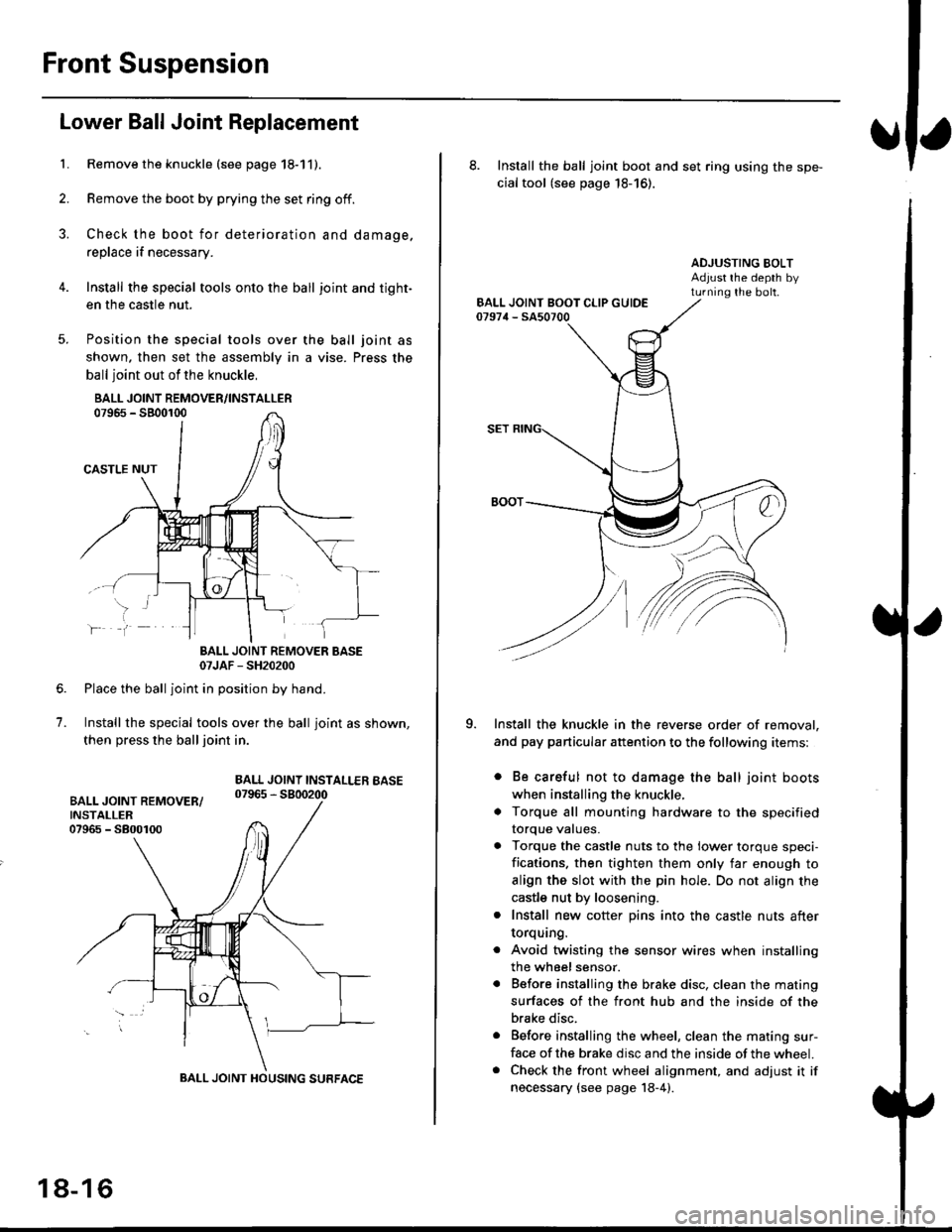
Install the special tools onto the ball joint and tight-
en the casfle nut.
Position the special tools over
shown. then set the assembly in
ball joint out of the knuckle,
BALL JOINT REMOVER/INSTALLER07965 - SB00r00
CASTLE NUT
the ball joint as
a vise. Press the
lf
7.
BALL JOINT REMOVER BASE07JAF - SH20200
Place the ball joint in position by hand.
Install the special tools over the ball joint as shown,
then press the ball joint in.
BALL JOINT INSTALLEB BASE07965 - 5800200
BALL JOINT HOUSING SURFACE
18-16
8. Install the ball joint boot and set ring using the spe-
cial tool (see page 18-16).
ADJUSTING BOLTAdjust rhe depth byturning the bolt.
Install the knuckle in the reverse order of removal,
and pay particular attention to the following items:
. Be careful not to damage the ball joint boots
when installing the knuckle,
. Torque all mounting hardware to the specified
torque values.
. Torque the castle nuts to the lower torque speci-
fications. then tighten them only far enough to
align the slot with the pin hole. Do not align the
castle nut by loosening.
. Install new cotter pins into the castle nuts after
torquang.
. Avoid twisting the sensor wires when installing
the wheel sensor.
. Before installing the brake disc. clean the mating
surfaces of the front hub and the inside of the
brake disc.
. Before installing the wheel, clean the mating sur-
face of the brake disc and the inside of the wheel.. Check the front wheel alignment, and adjust it if
necessary {see page 18-4).
Page 1159 of 2189

)
Brake Pedal
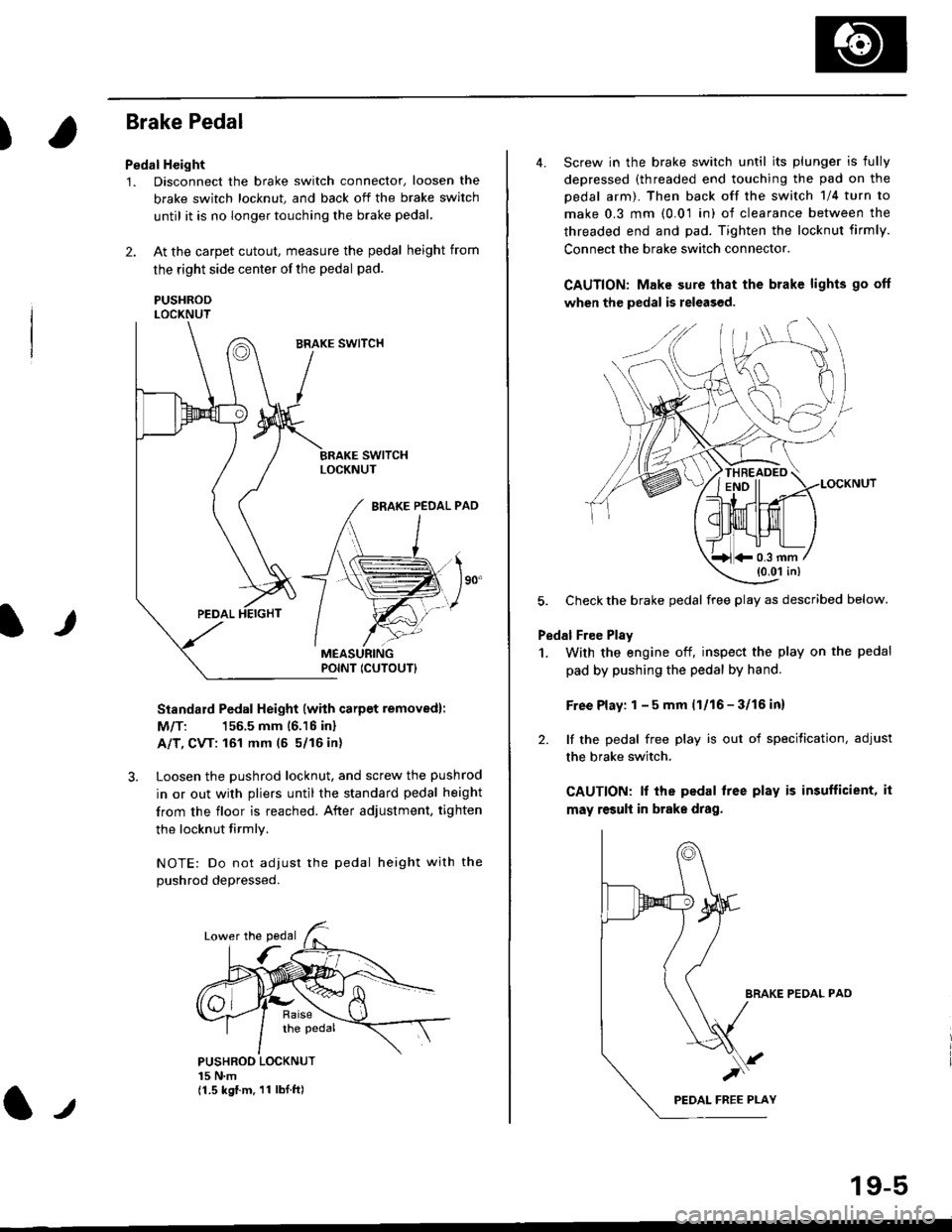
Pedal Height
1. Disconnect the brake switch connector, loosen the
brake switch locknut, and back off the brake switch
until it is no longer touching the brake pedal,
2. At the carpet cutout, measure the pedal height from
the right side center of the pedal pad.
PUSHRODLOCKNUT
Standard Pedal Height (with carpet removed):
M/T: 156.5 mm 16.16 inl
A/T, CVT: 161 mm (5 5/16 in)
3. Loosen the pushrod locknut, and screw the pushrod
in or out with pliers until the standard pedal height
from the floor is reached. After adjustment, tighten
the locknut firmly.
NOTE: Do not adiust the pedal height with the
Dushrod depressed.
It
PUSHROO LOCKNUT15 N.m(1.5 kgf.m. 11 lbI.ft)
POINT ICUTOUTI
4. Screw in the brake switch until its plunger is fully
depressed (threaded end touching the pad on the
pedal arm). Then back off the switch 1/4 turn to
make 0.3 mm (0.01 in) of clearance between the
threaded end and pad. Tighten the locknut firmly.
Connect the brake switch connector.
CAUTION: Make sure that the brake lights go off
when the pedal is released.
LOCKNUT
5. Check the brake pedal free play as described below.
Pedal Free Plsy
1. With the engine off, inspect the play on the pedal
pad by pushing the pedal by hand.
Free Play: 1 - 5 mm (1/16 - 3/16 inl
2. lf the pedal free play is out of specitication, adjust
the brake switch.
CAUTION: lf the pedal free play is insufficient, it
may result in brake drag.
BRAKE PEDAL PAO
)
19-5
*0.3 mm(0.01 in)
Page 1289 of 2189
Interior Trim
tReplacement
CAUTION:
. Put on gloves to protect your hands.
o When prying with a flat-tip screwdriver, wrap it with protective tape to prevent damage.
NOTE: Take care not to bend or scratch the trim and panels.
4D:
>: Clip locationsa>,2c >,2'lo >,2E >,2
r*'" n t-lt't
\wi, i
' l ll/
_tr* @,
CENTER PILLARUPPER TRIMREAR PILLARTRIM
LOCK CYLINDER TRIM
tl'
I
E'vBELT UPPERANCHOR(see page 20-85)
Disconnect thehigh mount brakelrght connector.
T SIDE TRIMRemove the rear seat cushion and rearseat side bolster lsee page 20-19]'.
)
lnstallation is the reverse of the removal procedure.
NOTE:
. lf necessary, replace any damaged clips.. Before installing the front seat belt upper anchor
and rear shelf. make sure there are no twists or
kinks in the seat belts.(cont'd)
B>,6
REAR SHELF
k"si
fEFT KICKPANEL
20-59
Page 2123 of 2189

Connector Views (cont'd)
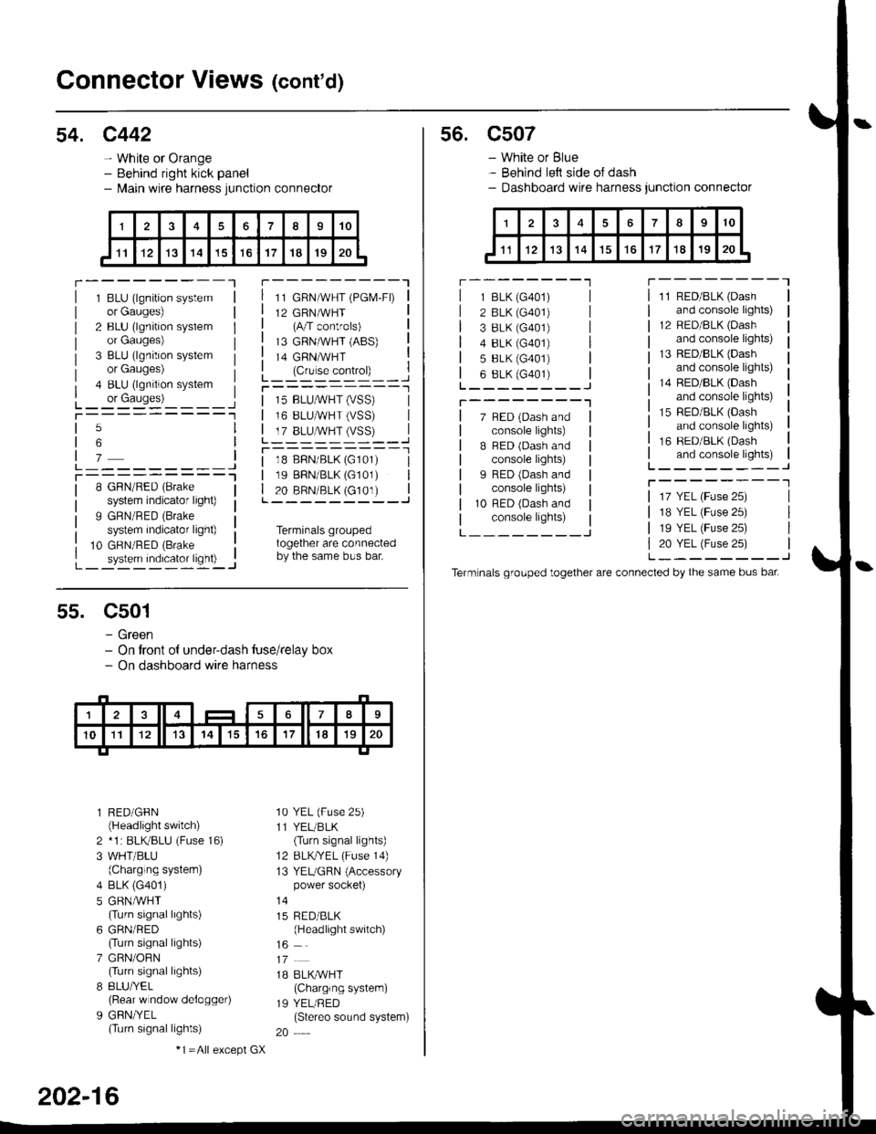
54. c442
- White or Orange- Behind right kick panel- l\,lain wire harness junction connector
r---------Tr---------"1
1 BLU (lgnition systemor Gauges)
2 BLU (lgnition syslemor Gauges)
3 BLU (lgnition systemor Gauges)
4 BLU (lgnition system
L_ or causes)L_-:-:::'-'�____Jt-----------1
11 GRN/WHT (PGM-FD
12 GRN/WHT(A/T controls)
13 GRNMHT (ABS)
14 GRNMHT
L_ lc,r'." .oIr"D_ _ _.jr----------_l
5
6
7L---------JT----------l8 GRN/RED (Brake
system indicator light)
9 GRN/RED (Brake
system indicator light)
10 GRN/RED (Brake
_ system indicator ligh0 -..1
| 15 BLUMHT (vSS) |I 16 BLUMHT (VSS) I
L T?_BLUSTrySS)--..]
l--------- - -l
| 18 BFN/BLK (G101) I| 19 BBN/BLK (G101) || 20 BRN/BLK (c101) |L---------J
Terminals groupedtogether are connectedby the same bus bar.
55. C501
- Green- On tront of under-dash tuse/relay box- On dashboard wire harness
l RED/GFN(Headlight switch)
2 *1 : BLKBLU (Fuse 16)
3 WHT/BLU(Charging systern)
4 BLK (G401)
5 GRNMHT(Turn signal lights)
6 GRN/RED(Turn signal lights)
7 GRN/ORN(Turn signal lights)
8 8LU/YEL(Rear w ndow delogger)
9 GFN/YEL(Turn signal lights)
'10 YEL (Fuse 25)
11 YEL/BLK(Turn signal lights)
12 BLKTYEL (Fuse 14)
13 YEUGRN (Accessorypower socket)
15 RED/BLK(Headlight switch)
1B BLK/WHT(Charglng system)
19 YEL/RED(Stereo sound system)
20
202-16
-1 =All e),cept GX
s6. c507
- White or Blue- Behind left side oJ dash- Dashboard wire harness junction connector
r --------'lT---------l
7 BED (Dash andconsole lights)
B BED (Dash andconsole lights)
I RED (Dash andconsole lights)
10 RFD (Dash andconsole lights)
11 RED/BLK (Dash
and console lights)
12 RED/8LK (Dash
and console lights)
13 RED/BLK {Dashand console lights)
14 RED/BLK (Dash
and console lights)
15 RED/BLK (Dash
and console lights)
16 RED/BLK (Dash
and console lights)L--------J
T--------T
L---_---_J
1 BLK (G401)
2 BLK (G401)
3 8LK {G401)4 8LK (G401)
5 BLK (G401)
6 8LK (G401)L________J
T--------"1
17 YEL (Fuse 25)
18 YEL (Fuse 25)
19 YEL (Fuse 25)
20 YEL (Fuse 25)L--------J
Term nals grouped together are connected by the same bus bat