1996 HONDA CIVIC battery
[x] Cancel search: batteryPage 2066 of 2189
Security System (conrd)
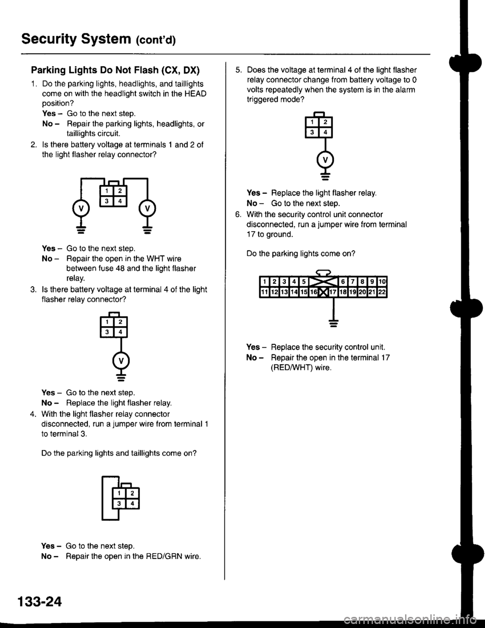
Parking Lights Do Not Flash (CX, DX)
1 . Do the parking lights, headlights, and taillights
come on with the headlight switch in the HEAD
position?
Yes - Go to the next step.
No - Repair the parking lights, headlights, or
taillights circuit.
2. ls there battery voltage at terminals 1 and 2 of
the light flasher relay connector?
dHl
.t.
Yes - Go to the next step.
No - Repair the open in the WHT wire
between fuse 48 and the light flasher
relay.
ls there battery voltage at terminal 4 of the light
flasher relay connector?
-F-,
tlllJt3l4l
Intvl
r=
Yes - Go to the next step.
No - Replace the light flasher relay.
With the light flasher relay connector
disconnected, run a jumper wire from terminal 1
to terminal 3.
Do the parking lights and taillights come on?
Yes - Go to the next step.
No - Repair the open in the RED/GRN wire.
133-24
5. Does the voltage at terminal 4 of the light flasher
relay connector change from battery voltage to 0
volts repeatedly when the system is in the alarm
triggered mode?
Yes - Replace the light flasher relay.
No - Go to the next step.
With the security control unit connector
disconnected, run a jumper wire from termrnal
17 to ground.
Do the parking lights come on?
Yes - Replace the security control unit.
No - Repair the open in the terminal 17
(REDAIVHT) wire.
q
I=
Page 2067 of 2189
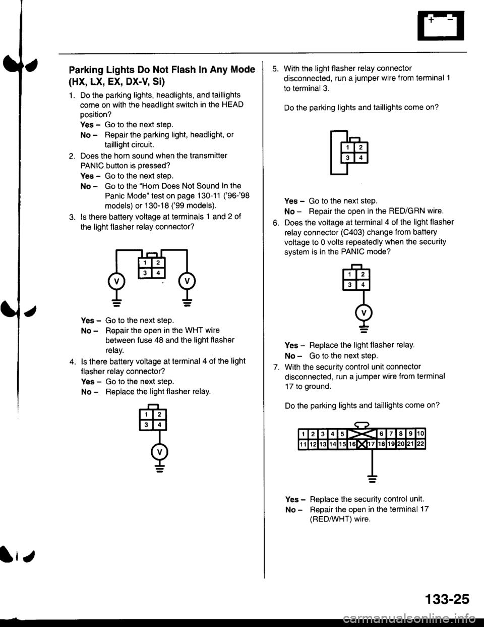
Parking Lights Do Not Flash In Any Mode
(HX, LX, EX, DX-V Si)
1. Do the parking lights, headlights, and taillights
come on with the headlight switch in the HEAD
oosition?
Yes - Go to the next steo.
No - Repair the parking light, headlight, or
taillight circuit.
2. Does the horn sound when the transmitter
PANIC button is oressed?
Yes - Go to the next step.
No - Go to the "Horn Does Not Sound In the
Panic Mode" test on page 130-11 ('96-98
models) or 1 30-18 ('99 models).
3. ls there battery voltage at terminals 1 and 2 of
the light flasher relay connector?
Yes - Go to the next step.
No - Reoair the open in the WHT wire
behveen fuse 48 and the liqht flasher
reray.
ls there battery voltage at terminal 4 ol the light
flasher relay connector?
Yes - Go to the next steD.
No - Replace the light flasher relay.
133-25
5. With the light flasher relay connector
disconnected, run a jumper wire from terminal .l
to terminal 3.
Do the parking lights and taillights come on?
o.
Yes - Go to the next step.
No - Repair the open in the RED/GRN wire.
Does the voltage at terminal 4 of the light flasher
relay connector (C403) change from battery
voltage to 0 volts repeatedly when the security
svstem is in the PANIC mode?
Yes - Replace the light flasher relay.
No - Go to the next steP.
7. With the security control unit connector
disconnected, run a jumper wire from terminal
17 to ground.
Do the parking lights and taillights come on?
Yes - Replace the security conlrol unit.
No - Repair the open in the terminal 17
(REDMHT) wire.
q
I=
Page 2069 of 2189
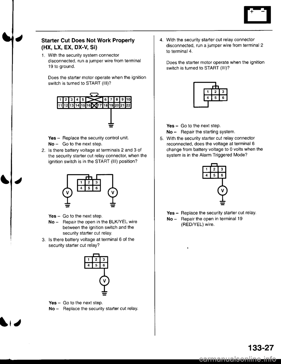
Starter Cut Does Not Work Properly
(HX, LX, EX, DX-V, Si)
1 . With the security system connector
disconnected, run a jumper wire f rom terminal
19 to ground.
Does the starter motor operate when the ignition
switch is turned to START (lll)?
2.
Yes - Replace the security control unit.
No - Go to the next steD.
ls there baltery voltage at terminals 2 and 3 of
the security starter cut relay connector, when the
ignition switch is in the START (lll) position?
Yes - Go to the next step,
No - Reoair the ooen in the BLK/YEL wire
between the ignition switch and the
security starter cut relay.
ls there battery voltage at terminal 6 of the
securitv starter cut relav?
Yes - Go to the next steo.
No - Replace the security starter cut relay.
3.
@
I=
r
133-27
4. With the security starter cut relay connector
disconnected, run a jumper wire from terminal 2
to terminal 4.
Does the slarter motor operate when the ignition
switch is turned to START (lll)?
5.
Yes - Go to the next step,
No - Repair the starting system.
With the security starter cut relay connector
reconnected, does the voltage at terminal 6
change from battery voltage to 0 volts when the
system is in the Alarm Triggered Mode?
Yes - Replace the security starter cut relay.
No - Repair the open in terminal 19
(BED/YEL) wire.
4
I=
Page 2070 of 2189
Security System (cont'd)
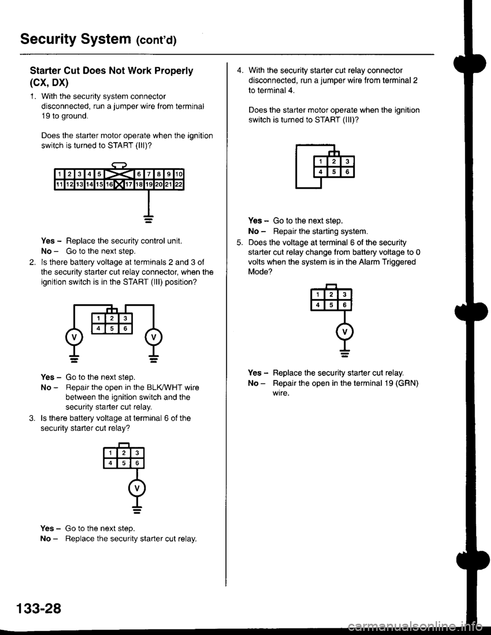
Starter Cut Does Not Work Properly
(cx, Dx)
1 . With the security system connector
disconnected, run a jumper wire f rom terminal
19 to ground,
Does the starter motor operate when the ignition
switch is turned to START (lll)?
Yes - Replace the security control unit.
No - Go to the next steo.
ls there battery voltage at terminals 2 and 3 of
the security starter cut relay connector, when the
ignition switch is in the START (lll) position?
Yes - Go to the next step.
No - Repair the open in the BLKMHT wire
between the ignition switch and the
security starter cut relay.
ls there battery voltage at terminal 6 of the
securitv starter cut relav?
Yes - Go to the next step.
No - Beplace the security starter cut relay.
4
o
t_=
133-28
4. With the security starter cut relay connector
disconnected, run a jumper wire from terminal 2
to terminal 4.
Does the starter motor operate when the ignition
switch is turned to START (lll)?
Yes - Go to the next steo.
No - Repair lhe starting system.
Does the voltage at terminal 6 of the security
starter cut relay change trom battery voltage to 0
volts when the system is in the Alarm Triggered
Mode?
Yes - Replace the security starter cut relay.
No - Repair the open in the terminal 19 (GRN)
wtre.
q
I=
Page 2075 of 2189
How the Circuit Works
The two outside mirrors are controlled by the power
mirror switch. Each mirror has two reversible
motors: one motor moves the mirror up and down
and the other motor moves the mirror lett and right.
The power mirror switch contains four switches to
control mirror adjustment, and two switches to
select the left or right mirror With the ignition in ON
(ll), battery voltage is supplied to the power mirror
swrtch. The mirror selector switch directs voltage
from two of the direction switches to either the left
or the right mirror.
Mirror Up
When you press the "up" edge of the mirror
adjustment button, ground is supplied from one of
the up/down switch contacts to both mirrors; battery
voltage is supplied from the opposite up/down
switch contact through the mirror select switch. lf
the mirror select switch is in the left or right position,
battery voltage is supplied to the corresponding
mirror uo/down motor which then tilts the selected
mtrror uD.
Mirror Down
When you press the "down" edge of the mirror
adjustment button, battery voltage is supplied Irom
one of the up/down swilch contacts to both mirrors;
a ground is supplied from the opposite up/down
switch contact through the mirror select switch. lf
the mirror select switch is in the left or right position,
battery voltage is supplied to the corresponding
mirror up/down motor which then tilts the selected
mrrror oown.
Mirror Left
When you press the "|eft" edge of the mirror
adjustment button, battery voltage is supplied from
one of the lefuright switch contacts to both mirrors;
a ground is supplied from the opposite lefuright
switch contact through the mirror select switch. lf
the mirror select switch is in the left or right position,
battery voltage is supplied to the corresponding
mirror lefvright motor which then tilts the selected
mirror to the lett.
Mirror Right
When you press the "right" edge of the mirror
adjustment button, ground is supplied from one of
the lefvright switch contacts to both mirrors; battery
voltage is supplied from the opposite left/right switch
contact through the mirror select switch. lf the mirror
select switch is in the left or right position, battery
voltage is supplied to the corresponding mirror
lefuright motor which then tilts the selected mirror to
the right.
Refer to the Service Manual (Section 23, Electrical)
for speclfic tests of troubleshooting procedures
141-1
Page 2077 of 2189
How the Circuit Works
The two outside mirrors are controlled by the power
mirror switch. Each mirror has two reversible
motors: one motor moves lhe mirror uo and down
and the other motor moves the mirror left and right.
The power mirror switch contains four switches to
control mirror adjustment, and a switch lo select
the left or right mirror. With the ignition ON (ll),
battery voltage is supplied to the power mirror
switch. The mirror selector switch directs voltage
Irom the direction switches to either the left or rioht
mtrror.
Mirror Up
When you press the "up" edge of the mirror
adjustment button, voltage is supplied from one of
the UP switch contacts to both mirrors. With the
mirror select switch in the LEFT or RIGHT Dosition.
ground is provjded for the corresponding up/down
motor through the opposite UP switch contact.
Battery voltage is supplied to the mirror up/down
motor which then tilts the selected mirror uo.
Mirror Down
When you press the "down" edge of the mirror
adjustment button, ground is provided through one
of the DOWN switch contacts to both mirrors.
With the mirror select switch in the LEFT or RIGHT
position, voltage is supplied to the corresponding
up/down motor through the opposite DOWN switch
contact. Battery voltage is supplied to the mirror
up/down motor which then tilts the selected
mtrror down.
Mirror Left
When the mirror select switch is in the LEFT or
RIGHT position, and you press the "lett" edge of the
mirror adjustment button, voltage is supplied to both
corresponding mirror motors through one of the
LEFT switch contacts. Ground is provided for the
corresponding lefvright motor through the opposite
LEFT switch contact, 8attery voltage is supplied to
the mirror left /right motor which then tilts the
selected mirror left.
I,J
141-3
Mirror Right
When the mirror select switch is in the LEFT or
RIGHT position, and you press the '?ight" edge of
the mirror adjustment button, ground is provided to
both corresponding mirror motors through one of
the RIGHT switch contacts. Voltage is supplied to
the corresponding leruright motor through the
opposite RIGHT switch contact. Battery voltage is
supplied to the mirror left /right motor which then
tilts the selected mirror right.
Mirror Detoggers
With the ignition switch in ON (ll), battery voltage is
supplied to the mirror defogger switch. When you
press the mirror defogger switch ON, voltage is
supplied to both mirror defoggers, causing them to
heat up and remove any fog from the mirrors. The
opposite side of each defogger grid is connected to
g rou no.
Refer to the Service Manual (Section 23,
Body Electrical) for specific tests and
troubleshooting procedures.
Page 2110 of 2189
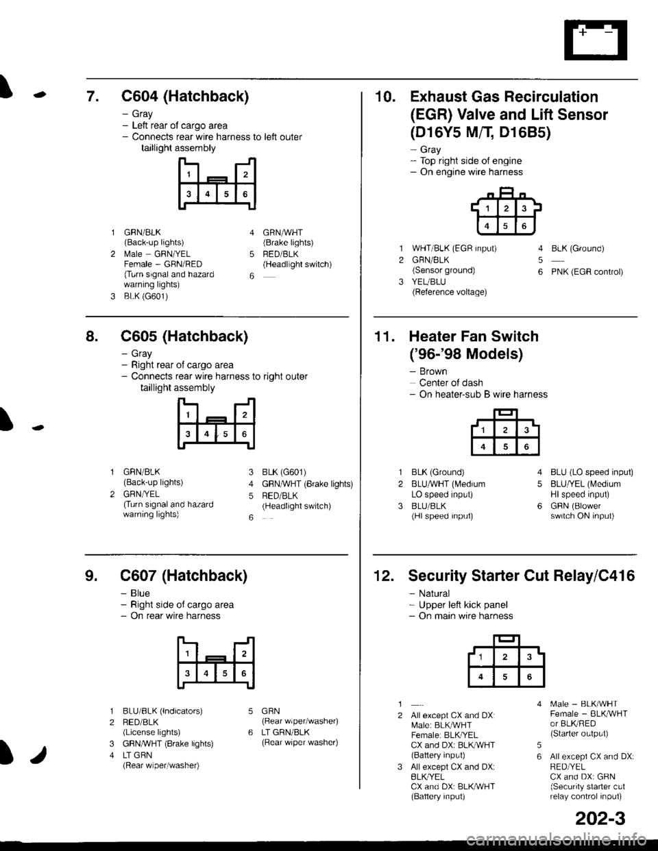
\7. C604 (Hatchback)
GRN/BLK(Back-up lights)
l\4ale GRNIYELFemale - GRN/RED(Turn signaland hazardwarning lights)
BLK (G601)
- Gray- Left rear ol cargo area- Connects rear wire harness to left outer
taillight assembly
4
5
6
1
2
GRNAVHT(Brake lights)
FED/BLK(Headllght switch)
10. Exhaust Gas Recirculation
(EGR) Valve and Lift Sensor
1
2
3
(D16Y5 MfI D1685)
- Gray- Top right side of engine- On engine wire harness
WHT/BLK (EGR input)
GRN/BLK(Sensor ground)
YEUBLU(Reference voltage)
4
5
6
BLK (Ground)
PNK (EGR control)
of cargo area
rear wire harness to right outer
assembly
n- -n
a t | _ a2a
l3I4t5tttl
IJ
I
8. C605 (Hatchback)
- Gray- Right rear- Connects
taillight
GRN/BLK(Back-up lights)
GRNTYEL(Turn signaland hazardwarning lights)
3
4
5
6
1
2
BLK (G601)
GFNAVHT (Brake lights)
RED/BLK(Headlight switch)
11. Heater Fan Switch
('96-'98 Models)
- Brown
Center of dash- On heater-sub B wire harness
BLK (Ground)
BLUAVHT (L4edium
LO speed input)
BLU/BLK(Hl speed input)
4
5
6
1
2
3
BLU (LO speed input)
BLU/YEL (Medium
Hlspeed input)
GFIN (Blowerswitch ON input)
9. C607 (Hatchback)
- Blue- Right side o{ cargo area- On rear wire harness
BLU/BLK (lndicators)
RED/BLK(License lights)
GBN,ryVHT (8rake lights)
LT GBN(Rear wiper/washe0
5
6
1
2
3
4
GRN(Rear wiper/washer)
LT GRN/BLK(Rear \/iper washer)
)/
202-3
12. Security Starter Cut Relay/C416
- Natural* Upper left kick panel- On main wire harness
1
2Allexcept CX and DXI[,4ale: BLK,^r'r'HTFemale: BLKI/ELCX and DXi BLI(WHT(Battery input)
All except CX and DX:BLK^/ELCX and DX: BLK/WHT(Baftery input)
[.4ale - BLK/WHTFemale - BLKAVHTor BLKRED(Starter output)
All excepi CX and DX:RED/YELCX and DX: GRN(Security starter c!1relay control inpul)
5
6
tl3'
Page 2111 of 2189
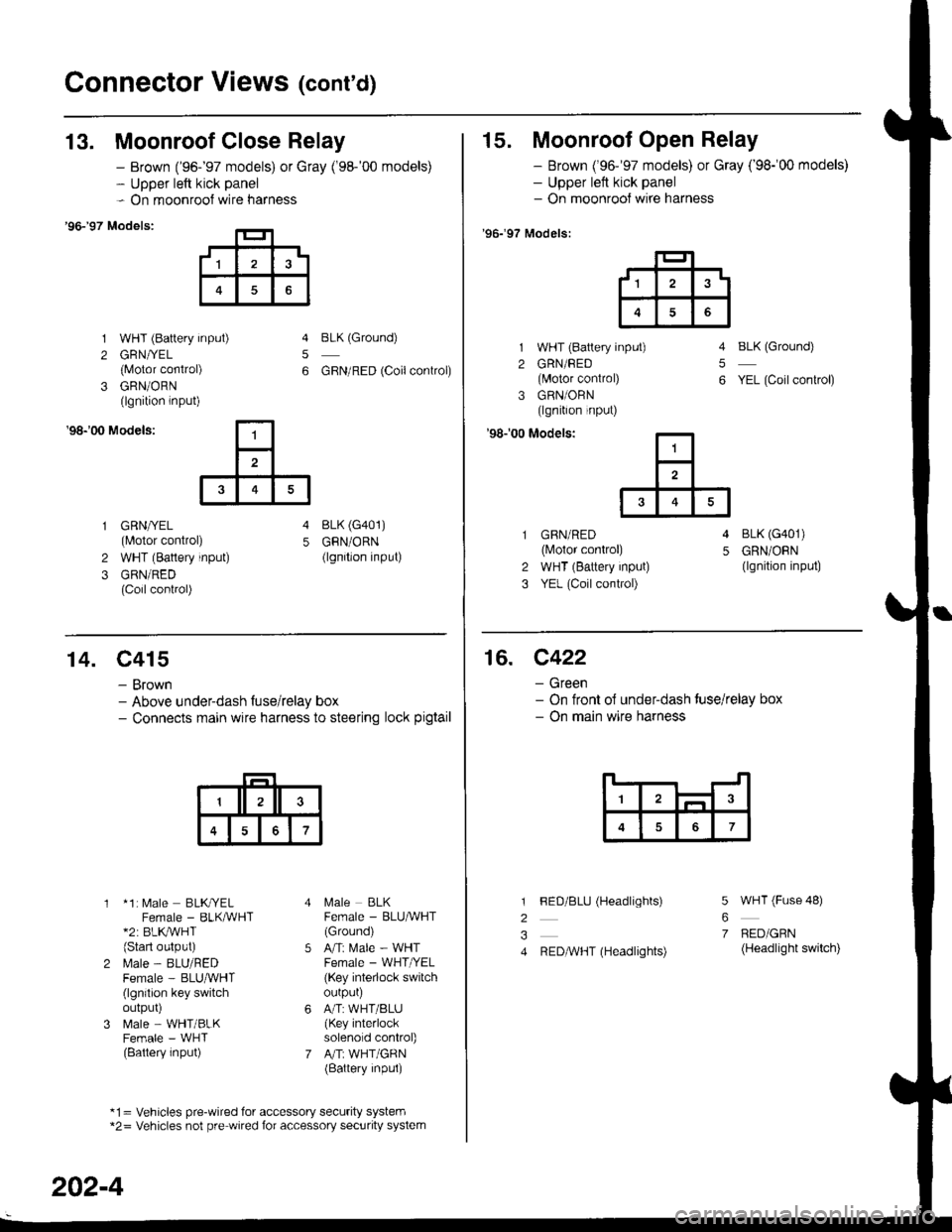
Connector Views (cont'd)
13. Moonroof Close Relay
'96-�97 Models:
1 WHT (Battery input)
2 GRN//EL
{Motor conirol)
3 GRN/ORN(lgnition lnput)
- Brown ('96-'97 models) or Gray ('98-'00 models)- Upper left kick panel- On moonroof wire harness
5
6
BLK (Ground)
GBN/RED (Coilconkol)
'98r00 Models:
GRN/YEL(Motor control)
WHT (Battery input)
GRN/RED(Coil control)
4 BLK (G401)
5 GRN/ORN(lgnition input)2
3
15. Moonroof Open Relay
- Brown ('96-'97 models) or Gray ('98-'00 models)- Upper left kick panel- On moonrool wire harness
'96.�97 Models:
1 WHT (Battery input)
2 GRN/FED(lvlotor control)
3 GRN/ORN(lgnition input)
'98r00 Modelsi
BLK (Ground)
YEL (Coil conkol)
5
6
GBN/RED(lvlotor control)
WHT (Battery input)
YEL (Coil control)
4 BLK (G401)
5 GRN/ORN(lgnition input)2
3
,1^t
6
14. C415
- Brown- Above underdash fuse/relay box- Connects main wire harness to steering lock pigtail
* 1: [,4ale BLKryELFemale - BLKMHT*2: BLK,/WHT(Start oulput)
l\.4ale - BLU/REDFemale - BLUruVHT(lgnilion key switchoutpur)
N4ale - WHT/BLKFemale - WHT(Battery input)
l\,4ale BLKFemale - BLU^VHT(Ground)
Ani Male - WHTFemale - WHT /EL
(Key interlock switchourpur)
A/T:WHT/BLU(Key interlocksolenold control)
A"rT: WHT/GRN(Battery inpul)
*1= Vehicles pre-wired for accessory security system*2= Vehicles not pre wired for accessory security system
202-4
16. C422
- Green- On tront ol under-dash tuse/relay box- On main wire harness
7
l
2
3
4
5
6
7
FED/BLU (Headlights)
REDAVHT (Headlights)
WHT (Fuse 48)
BED/GRN(Headlight switch)