Page 1229 of 2189
ABS Control Unit
Pulsers/Wheel
Sensors
Replacement
1. Remove the right side kick panel.
2. Disconnect the ABS control unit connecrors.
3. Remove the ABS control unit,
4. lnstall the ABS control unit in the reverse order of
removal,
CONNECTORS
19-76
Inspection
Check the front and rear pulser for chipped or dam-aged teeth.
Measure the air gap between the wheel sensor andpulser all the way around while rotating the pulser.
Slandard: 0.4 - 1.0 mm (0.02 - 0.04 in,
NOTE; lf the gap exceeds 1.0 mm (0.04 in), theprobability is a distorted suspension arm which
should be replaced.
Dbc brake typo
0.{ - 1.0 mm(0.02 - 0.04 in)
Drum brake typ6
1.
Page 1599 of 2189
JGau ge/lndicator/Terminal
With tachometer;
CONNECTOR "A"
{A/T GEAR POSITION INDICATOR}
Location lndex
CONNECTOR "8"
{GAUGE and INOICATOR)CONNECTOB "C"
CONNECTOR "D"
{ABS INDICATORI
SPEEDOMETER:Indicates 60 km/h at 637 rpm or
60 mph at 1,025 rpm o{thevehicle speed sensor (VSS).
A/T GEAR POSITIONINDICATORSee page 23 149
TACHOMETER:Indicates 100 rpm at200 pulses per minuteol the ignition controlmodule (lCMi.FUEL GAUGEENGINE COOLANT TEMPERATURE (ECT) GAUGE
(cont'd)
23-129
(GAUGE end INDICATORI
A1-----------+816
JlltlllulllllrL
c1 --------->c13
1ililil{ilrL
oooo o 0006^
)og @ @ o^o @ )'l |. o
Fl- - -> F5E1_ _ -->E5D1- --+05
oo/ \oo
Gauge/Sending Unit Test, page 23-142
Page 1611 of 2189

J
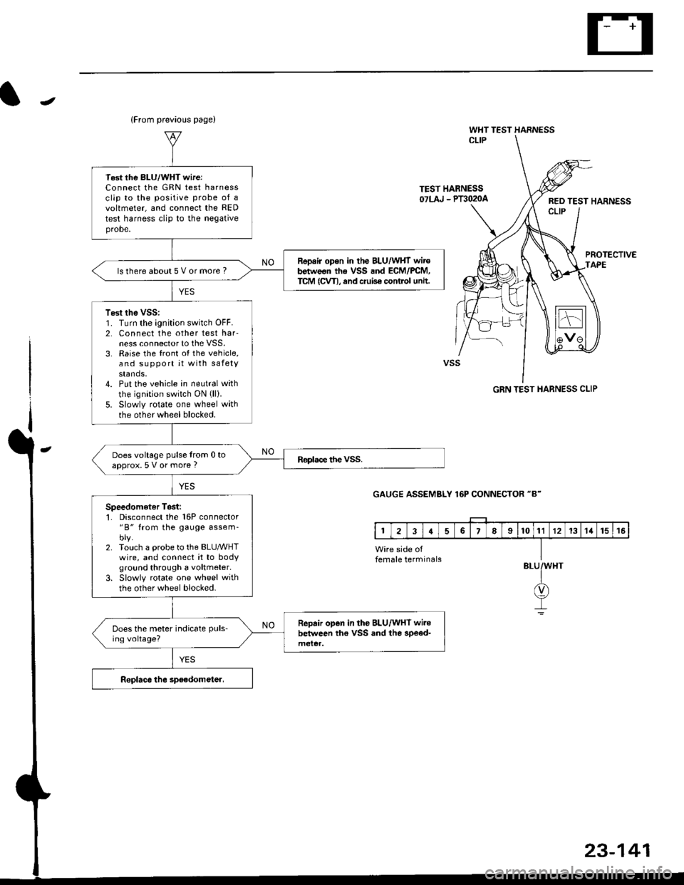
(From prevaous page)
WHT TEST HARNESSCLIP
TEST HABNESS07LAJ - Plil020aRED TEST HARNESSCLIP
PROTECTIVEAPE
GRN TEST HARNESS CLIP
GAUGE ASSEMBLY 16P CONNECTOR "8"
BLU
23-141
Tost the BLU/WHT wireiConnect lhe GRN test harnessclip to the positive probe of avoltmeter, and connect the RED
test harness clip to the negativeprobe.
Repair open in the BLU/WHT wirob€twoon the VSS and ECM/PCM,TCM (CVT), and cruise control untt.ls there about 5 V or more ?
Test the vss:1. Turn the ignition switch OFF.2. Connect the other test harness connector to the VSS.3. Raise the front ot the vehicle,and support it with safetystands,4. Put the vehicle in neutral with
the ignition switch ON (ll).
5. Slowly rotate one wheel withthe other wheel blocked.
Does voltage pulse from 0 toapprox.5 V or more ?
Speedometer Tosii'1. Disconnect the 16P connector"B" from the gauge assem-blv.2. Touch a probe to the BLUMHTwire, and connect it to bodyground through a voltmeter.
3. Slowly rotate one wheel with
the other wheel blocked.
Repair open in the BLU/WHT wi.ebelween th€ VSS and the 3pe€d-Does the meter indicate puls-
ing voltage?
female terminals
Page 1699 of 2189

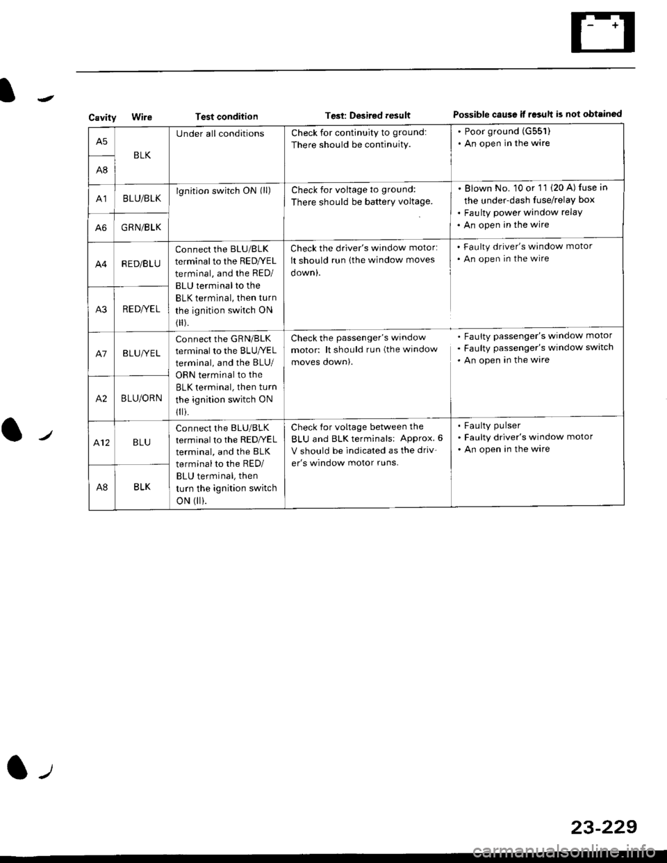
CavityWireTest conditionTest: Desired resultPossible caus€ if result is not obtainsd
BLK
U nderall conditionsCheck for continuity to ground:
There should be continuity.
. Poor ground (G551)
. An open in the wire
A8
A']BLU/BLKlgnitlon switch ON (ll)Check for voltage to ground:
There should be batterY voltage.
Blown No. 10 or '11 (20 A) fuse in
the under-dash fuse/relay box
Faulty power window relay
An open in the wireA6GRN/BLK
R ED/B LU
Connect the BLU/BLK
terminal to the RED/YEL
terminal, and the RED/
BLU terminal to the
BLK terminal, then turn
the ignition swilch ON
(
).
Check the driver's window motor:
It should run (the window moves
oown,.
Check the passenger's window
motor: lt should run (the window
moves qown,.
Check for voltage between the
BLU and BLK terminals: APProx. 6
V should be indicated as the driv-
er's window motor runs.
Faulty driver's window motor
An open in the wire
Faulty passenger's window motor
Faulty passenger's window switch
An open in the ware
Faulty pulser
FaLilty driver's window motor
An open in the wire
A3RE D/YE L
A7BLUI/E L
connect the GRN/BLK
terminal to the BLUryEL
terminal, and the BLU/
ORN terminal to the
BLK terminal, then turn
the ignition switch ON
1
i.
A2BLU/ORN
412BLU
Connect the BLU/BLK
terminal to the REDI/EL
terminal, and the BLK
terminal to the RED/
BLU terminal, then
turn the ignition switch
oN (|| ).
A8BLK
23-229
Page 1701 of 2189

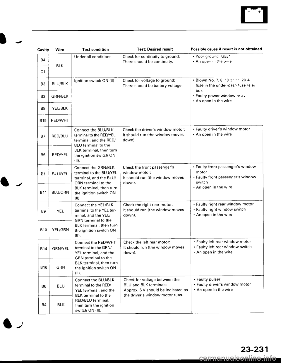
CavityWireTest conditionTest: Desired resultPossible caus! d r"suh rs nol obtrincd
to:
c1
BLK
UnderallconditionsCheck for continuity to groundl
There should be continuity., An ope^ ^ :he tt .e
. Blown No.7.6 10 r' " 20 A
fuse in the unde. oast f.se 'e a,
box. Faulty power windo$ 'e a,. An open in the wire
B3BLU/BLKlgnition switch ON (ll)Check for voltage to grou nd:
There should be battery voltage.
B2GRN/BLK
YE L/BLK
R EDA/VHT815
81RED/BLU
RED/YEL
Connect the BLU/BLK
terminal to the RED/YEL
terminal, and the RED/
BLU terminal to the
BLK terminal, then turn
the ignition switch ON
1I i.
Check the driver's window motorl
It should run (the window moves
oown).
. Faulty driver's window motor
. An open in the wire
B1BLUIVEL
Connect the GRN/BLK
terminal to the BLU|YEL
terminal, and the BLU/
Check the front passenger's
wrnoow motor:
It should run (the window moves
Fau lty front passenger's window
motor
Faulty front passenger's window
An open in the wire
811BLU/ORNBLK terminal, then turn
the ignition switch ON
0 r).
B9YEL
connect the YEL/BLK
terminal to the YEL ter-
minal, and the YEU
GRN terminal to the
BLK terminal, then turn
the ignition switch ON
0 r).
Check the right rear motor:
It should run (the window moves
down).
Fauity right rear window motor
Fau lty right window switch
An open in the wire
Bt0YEUGRN
814GRNI/EL
connect the RED,ryVHT
terminal to the GRN/
YEL terminal, and the
GRN terminal to the
BLK terminal, then turn
the ignition switch ON
0 r).
Check the left rear motor:
It should run (the window moves
Faulty left rear window motor
Faulty left rear window switch
An open in the wire
816GRN
B6BLU
Connect the BLU/BLK
terminal to the RED/
YEL terminal, and the
BLK terminal to the
RED/BLU terminal,
then turn the ignition
switch ON (ll).
Check for voltage between the
BLU and BLK terminalsl
Approx. 6 V should be indicated as
the driver's window motor runs.
Faulty pulser
Faulty driver's window motor
An open in the wire
B4BLK
23-231
Page 1833 of 2189
How To Use This Manual
Troubleshooting Tests (cont'd)
4. Turn on the short finder. This creates a
pulsing magnetic field around the wiring
between the fuse box and the short.
5. Beginning at the fuse box, slowly move
the short finder along the circuit wiring.
The meter will show current Dulses
through sheet metal and body trim. As
long as the meter is between the fuse and
lhe short, the needle will move with each
current pulse. Once you move the meter
past the point of the short, the needle will
stop moving. Check the wiring and
connectors in this area to locate the cause
of the short.
co
Page 1917 of 2189
- How the Gircuit Works
With the ignition switch in ON (ll) or START (lll),
battery voltage is supplied through fuse 15 and
the BLI(WHT and BLK/YEL wire to the vehicle
speed sensor (VSS). The sensor is grounded by
the BLK wire to G1 01 . The speedometer and
other control units in the circuit supply about 5
volts to the BLU/WHT wire. The vehicle soeed
sensor (VSS) intermittently grounds the
BLUMHT wire which generates a pulsed signal
in it. The number of pulses per minute
increases/decreasos with the soeed of the car.
Reter to th€ Service Manual (Section 23, Electrical)
tor specific tosts or troubleshooting procedures.
33-1
Page 1980 of 2189

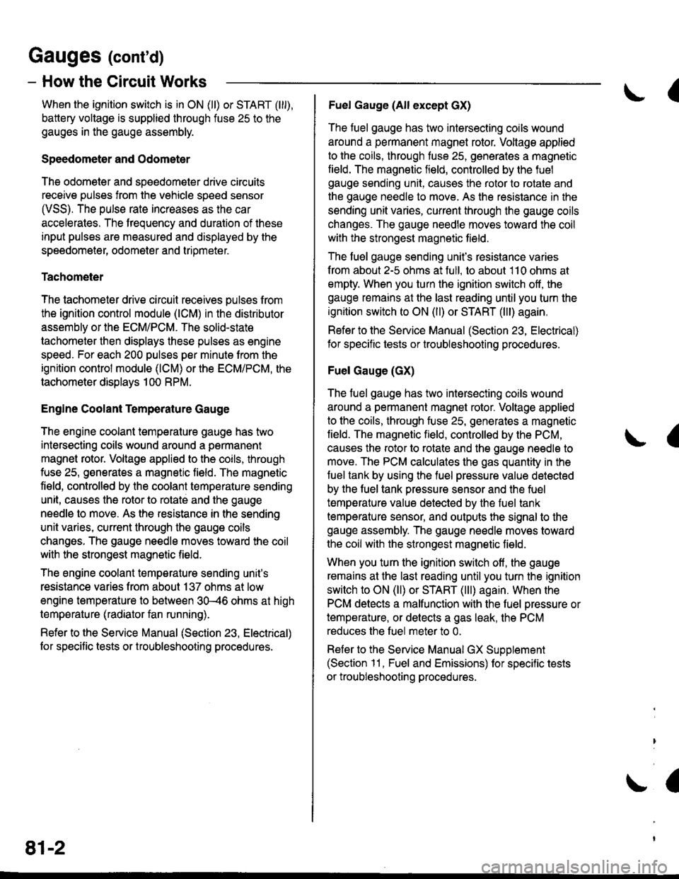
Gauges (cont'd)
- How the Gircuit Works
When the ignition switch is in ON (ll) or START (lll),
battery voltage is supplied through fuse 25 to the
gauges in the gauge assembly.
Speedometer and Odometer
The odometer and soeedometer drive circuits
receive pulses from the vehicle speed sensor
(VSS). The pulse rate increases as the car
accelerates. The frequency and duration of these
input pulses are measured and displayed by the
speedometer, odometer and tripmeter.
Tachometer
The tachometer drive circuit receives pulses from
the ignition control module (lCM) in the distributor
assembly or the ECM/PCM. The solid-state
lachometer then displays these pulses as engine
speed. For each 200 pulses per minute from the
ignition control modul€ (lCM) or the ECM/PCM, the
tachometer displays 100 RPM.
Engine Coolant Temperature Gauge
The engine coolant temperature gauge has two
intersecting coils wound around a permanent
magnet rotor. Voltage applied to the coils, through
fuse 25, generates a magnetic lield. The magnetic
field, controlled by the coolant temperature sending
unit, causes the rotor to rotate and the gauge
needle to move. As the resistance in the sending
unit varies, current through the gauge coils
changes. The gauge needle moves toward the coil
with the strongest magnetic field.
The 6ngine coolant temperature sending unit's
resistance varies from about 137 ohms at low
engine temperature to between 3H6 ohms at high
temperature (radiator fan running).
Refer to the Service Manual (Section 23, Electrical)
for specific tests or troubleshooting procedures.
81-2
(
Fuel Gauge (All except cX)
The fuel gauge has two intersecting coils wound
around a permanent magnet rotor. Voltage applied
to the coils, through tuse 25, generates a magnetic
field. The magnetic field, controlled by the fuel
gauge sending unit, causes the rotor to rotate and
the gauge needle to move. As the resislance in the
sending unit varies, current through the gauge coils
changes. The gauge needle moves toward the coil
with the strongest magnetic field.
The fuel gauge sending unit's resistance varies
from about 2-5 ohms at full, to about 110 ohms at
empty. When you turn the ignition switch off, the
gauge remains at the last reading until you turn the
ignition switch to ON (ll) or START (lll) again,
Refer to the Service Manual (Section 23, Electrical)
for specific tests or troubleshooting procedures.
Fuel Gauge (GX)
The fuel gauge has two intersecting coils wound
around a permanent magnet rotor. Voltage applied
to the coils, through fuse 25, generates a magnetic
field. The magnetic field, controlled by the PCM,
causes the rotor to rotate and the gauge needle to
move. The PCM calculates the gas quantity in the
fuel tank by using the fuel pressure value detected
by the tuel tank pressure sensor and the fuel
temperature value detected by the fuel tank
temperalure sensor, and outputs the signal to the
gauge assembly. The gauge needle moves toward
the coil with the strongest magnetic field.
When you turn the ignition switch off , the gauge
remains at the last reading until you turn the ignition
switch to ON (ll) or START (lll) again. When the
PCM detects a malfunction with the fuel pressure or
temperature, or detects a gas leak, the PCM
reduces the fuel meter to 0.
Refer to the Service Manual GX Supplement
(Section 11 , Fuel and Emissions) for specific tests
or troubleshooting procedures.
a
a