1996 HONDA CIVIC Distributor o ring
[x] Cancel search: Distributor o ringPage 134 of 2189
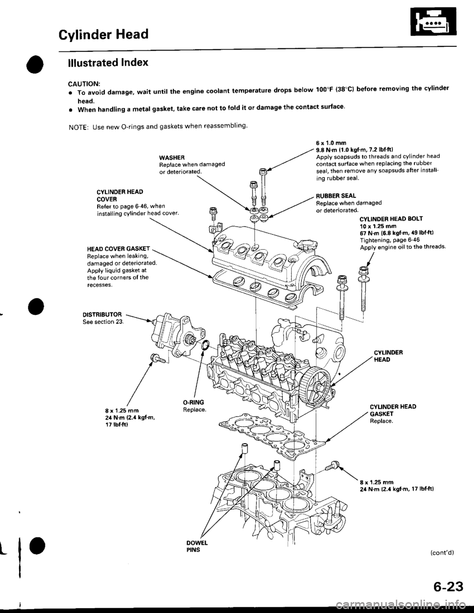
Gylinder Head
lllustrated Index
CAUTION:
. To avoid damage, wait until the engine coolant temperatule drops below 100"F (38'C) before removing the cylinder
head.
. When handling a metal gasket, take care not to fold it or damage the contact surface'
NOTEr Use new O-rings and gaskets when reassembling'
CYLINDER HEAD
COVERRefer to page 6 46, when
installing cylinder head cover.
WASHERReplace when damaged
or deteriorated.
O.RINGReplace.
6x1.0mm9.8 N.m 11.0 kgf.m, 7.2 lbfft)Apply soapsuds to threads and cylinder head
contact surface when replacing the rubber
seal, then temove any soapsuds after install
ing rubber seal.
RUBBER SEALReplace when damagedor deteriorated.
CYLINDER HEAD BOI-T
10 x 1.25 mm67 N.m 16.8 kgf m, a9 lbt'ft)
Tightening, Page 6-46
Apply engine oilto the threads.HEAD COVEB GASKETReplace when leaking,
damaged or deteriorated.Apply liquid gasket at
the four corners ol therecesses,
DISTRIBUTORSee section 23.
8 x 1 .25 mm24 N.m (2.4 kgf.m,17 tbt.ft)
CYLINDER HEADGASKETReplace.
8 x 1.25 mm24 N.m {2.4 kgf m, 17 lbf ftl
t(cont'd)
6-23
PINS
Page 175 of 2189
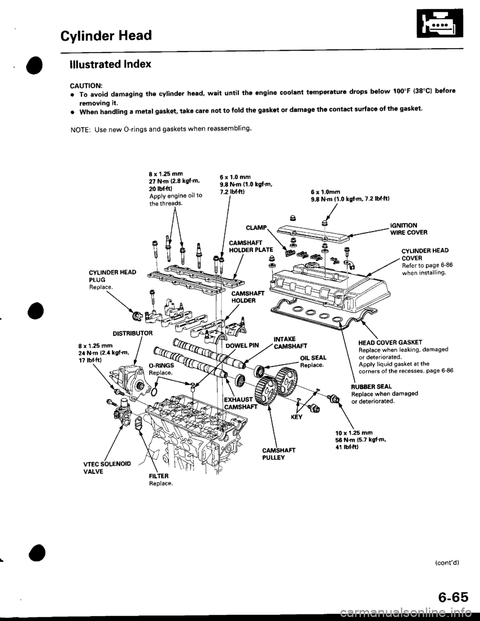
Cylinder Head
lllustrated Index
CAUTION:
. To avoid damaging the cylinder head, wait until the engine coolant tempsraturo drops below 100"F (38"C1 bofote
removing it,
. when handling a metal gasket, take caro not to fold the gaskot or damage the contact surface of the gasket.
NOTE: Use new O-rings and gaskets when reassembling.
CYLINDER HEAO
PLUGReplace.
)@
DISTRIBUTOR
8 x 1 ,25 mm
27 N.m P.E kgl m.
20 tbf.foApply engine oil to
the threads.
cr.rMp.S
CAMSHAFT A"o''*t*'; wes@
OIL SEALReplace.
6 x l,omm9.8 N'm tl.0 kgt'm,7.2lbf ft)
RUBBER SEALReplace when damaged
or detedorated.
6x1.0mm9.8 N.m (1.0 kgf'm,
7.2 rbnftl
fi%
IGNMONWIRE COVER
CYLINOER HEAD
COVERRefer to page 6-86
when installing
HEAD COVER GASKETReplace when leaking, damaged
or deteriorated.Apply liquid gasket at thecorners of the recesses, Page 6-86
8 x 1,25 mm24 N.m {2.4 kgf'm,
1? tbf.ftl
EXHAUST
10 x 1.25 mm56 N.m (5.7 kgf m,,r1 lbl.ft)
(cont'd)
6-65
Page 272 of 2189
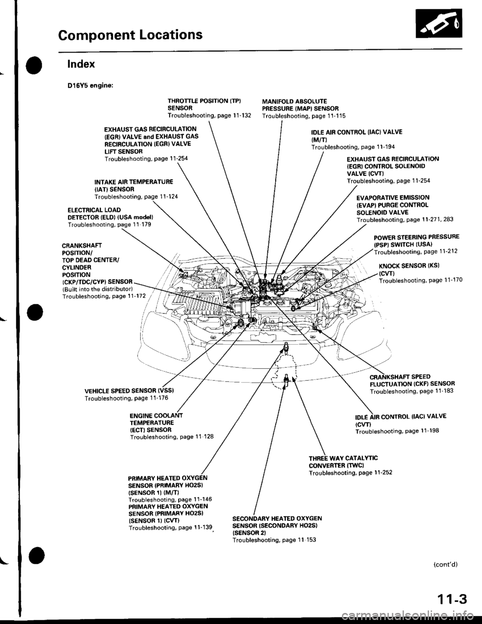
Gomponent Locations
L
lndex
D16Y5 engine:
{IATISENSORTroubleshooting,
ELECTRICAL LOADDETECTOR IELD) (USA mod6l)Troubleshooting, page 11 179
THROTTLE POSITION ITP)SENSORTroubleshooting, page 1 1-132
MANIFOLD ABSOLUTEPRESSURE IMAPI SENSORTroubleshooting, page 1'l-115
EXHAUST GAS RECIRCULATION
IEGRI VALVE and EXHAUST GAS
RECIRCULATION IEGRI VALVE
LIFT SENSORTroubleshooting, page'l 1-254
INTAKE AIR TEMPERATUR€
IDLE AIR CONTROL (IAC) VALVE
{M/T)Troubleshooting, page 1 1-194
EXHAUST GAS RECIRCULATION{EGRI CONTROL SOLENOIDVALVE ICW)Troubleshooting. page 1 1-254
EVAPORATIVE EMISSIONIEVAPI PUNGE CONTROLSOLENOID VALVETroubf eshooting, Page 1 1'21 1, 243
CRANKSHAFTPOS|TTON/TOP DEAD CENTER/CYLINDERPOS|T|ON
POWER STEERING PRESSURE(PSP) SWITCH (USAI
Troubleshooting, Page 1 1-212
KNoCK SENSoR (Ks)
(cwl
Troubleshooting, Page 1 1'170ICKP/TDC/CYP} SENSOR(Built into the distributor)Troubleshooting, Page 1 1'172
VEHICLE SPEED SENSORTroubleshooting, Page 1 1-176
FLUCTUATION (CKF} SENSOR
Troubleshooting, Page 1 1 -183
ENGINE COOLANTTEMPERATUREIECT) SENSORTroubleshooting, Page 11 128
IDT.ECONTROL IIACI VALVE
{cw)Troubleshooting, Page 11 198
WAY CATALYTICCONVERTER ITWCITroubleshooting, Page 1 1-252PRIMARY TIEATEDSENSOR {PNIMARY HO2SI
tsENsoR 1t {M/TlTroubleshooting, Page'l 1-146
PRIMARY HEATED OXYGENSENSOR (PRIMARY HO2SI
tsENsoR 1l {cw}Troubleshooting, Page 1 1-139
SECONDARY HEATED OXYGENSENSOR {SECONDARY HO2S){SENSOR 2)Troubleshooting, page 11 153
(cont'd)
1 1-3
Page 273 of 2189
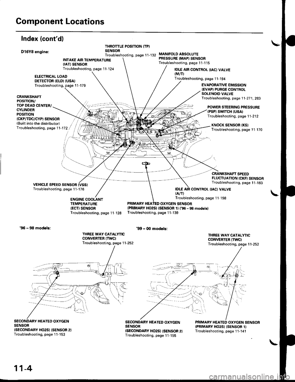
Component Locations
Index (cont'd)
D16Y8 enginc:
THROTTLE POSITION {TPISENSORTroubleshooting, page 1 1-132
ELECTRICAL LOADDETECTOR IELDI {USAI
INTAKE AIR TEMPERATUREIIATISENSORTroubleshooting, page 1 1,124
MANIFOLO ABSOLUTEPRESSURE {MAPI SENSORTroubleshooting, page 1 1-1 15
IDI.E{A/T)
IDI.E AIR CONTROL IIACI VALVElMtflTroubleshooting, page 1 1-194
Troubleshooting, page 1 1-179EVAPORATIVE EMISSIONIEVAPI PURGE CONTROLSOLENOIO VALVETroubleshooting, page 1 1 27 1. 283CRANKSHAFTPOSTTTON/TOP DEAD CENTER/CYLINDERPOStTtON
POWER STEERING PRESSURE(PSPI SWTTCH |USA)Troubleshooting, page 1 1-212{CKP/TI'C/CYPI SENSOR(Built into the distributor)Troubleshooting. page 1 1-172KNOCK SENSOR IKSITroubleshooting, page 11 170
CRANKSHAFT SPEEDFLUCTUANON ICKFI SENSORTroubleshooting, page 1 1,183
CONTROL {IACI VALVE
ENGINE COOLANTTEMPERATURE{ECTI SENSORTroubleshooting, page 11 128
Troubleshooting, page 11 198
PRIMARY HEATED OXYGEN SENSOR{PRIMARY HO2S} (SENSOR 1l {'96 - 98 modolslTroubleshooting, page 1 1-139
'9!t - 00 modols:'96 - 98 modols:
THREE WAY CATALYNCCONVERTER ITWCITroubl6shooting, page 1 1-252
THREE WAY CATALYNCCONVERTER ITWCITroubleshooting. page 1 1-252
SECONDARY HEATED OXYGENSENSOn(SECONDARY HO2SI (SENSOR 2ITroubleshooting, page 1 1-153
SECONDARY HEATED OXYGENSENSOBISECONDARY HO2S} ISENSOR 2ITroubloshooting, page 1 1-155
PRIMARY HEATEO OXYGEN SENSORIPRIMARY HO2SI ISENSOR 1ITroubleshooting, page 1 1-141
11-4
Page 275 of 2189
Component Locations
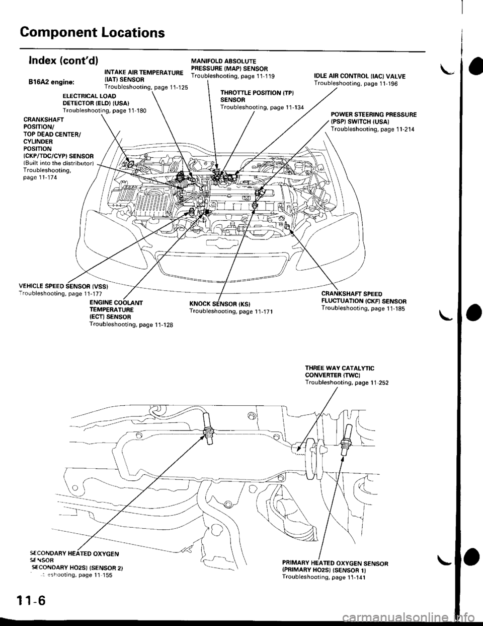
Index (cont'dl
Bl6A2 engine:
INTAKE AIR TEMPERATURE{IAT} SENSORTroubleshooting, page 1'1-125
MANIFOLO AESOLUTEPRESSURE IMAPI SENSORTroubleshooting. page 11-1 19IOLE AIR CONTROL {IAC) VALVETroubleshooting, page 1 1,196
ELECTRICAL LOADDETECTOR IELDI (USA)
Troubleshooting, page 1 1-180
THROTTLE POSITION ITPISENSORTroubleshooting, page 11-134
CRANKSHAfiPOStTtON/TOP DEAD CENTER/CYLINDERPOStTtON{CKP/TDC/CYPI SENSOR(Bualt into the distributor)Troubleshooting,page 11-174
POWER STEERING PRESSURE{PSPI SWTTCH (USA)
Troubleshooting, page 1 1-214
VEHICLE SPEED SENSOR {VSS}Troubleshooting, page 1 1-177
ENGINE
CRANKSHAFT SPEEDFLUCTUATION (CKFI SENSORTroubleshooting, page 11- t85TEMPERATUREIECTI SENSORTroubleshooting, page I 1-128
THREE WAY CATALYTICCONVERTER ITWC)Troubleshooting, page 1 1,252
S€CONOARY HEATED OXYGENsf rlsoR
sfCoNDARY HO2SI {SENSOR 2): ?shootrng, page 11 155
-6
PRIMARY HEATED OXYGEN SENSORIPRIMARY HO2S) ISENSOR 1ITroubleshooting, page 1 1-141
11
Page 435 of 2189
PGM-FI System
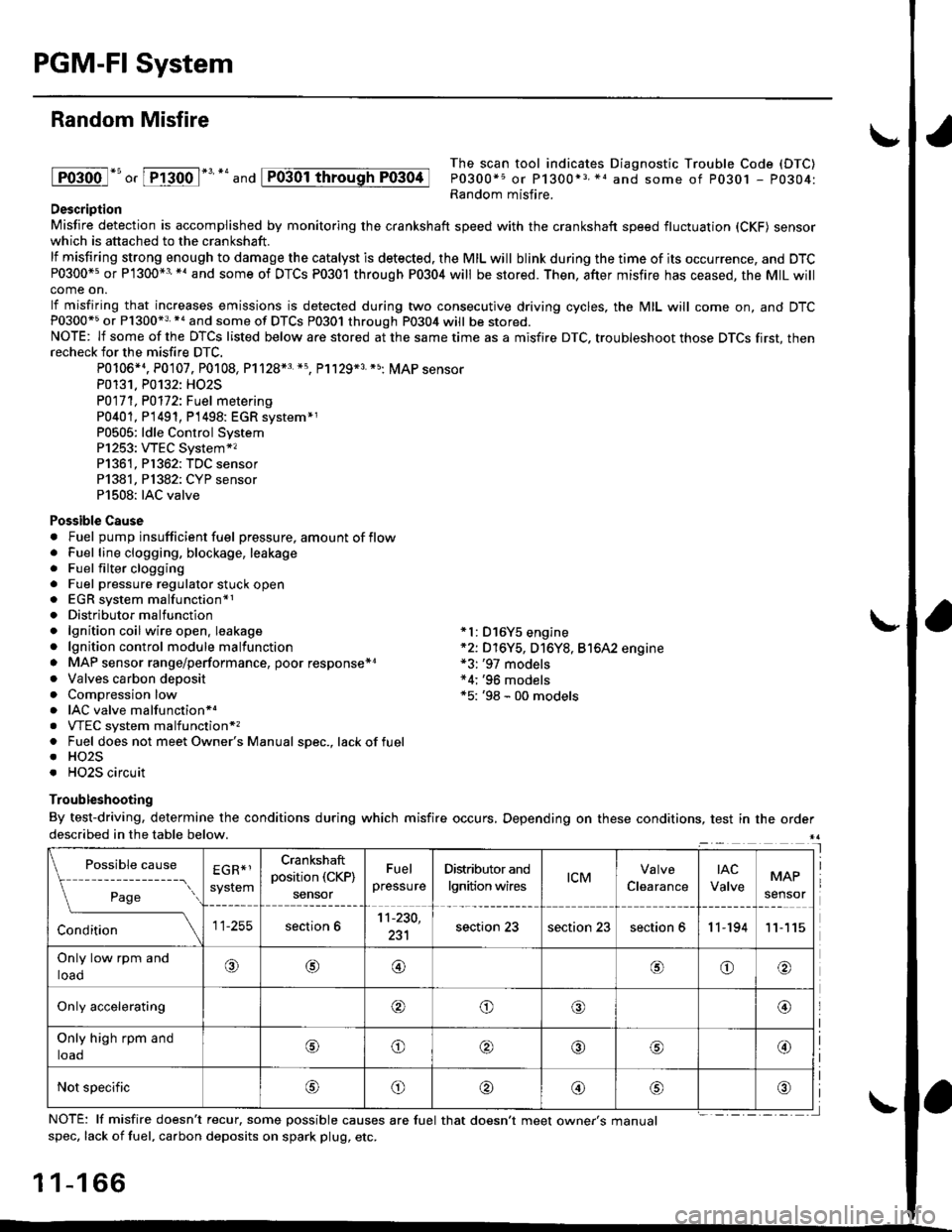
Random Misfire
lFoioo l*u o, [FTioo l*' *' and
The scan tool indicates Diagnostic Trouble Code (DTC)
P0300*5 or P1300*3 *1 and some of P0301 - P0304:Random misfire.Description
Misfire detection is accomplished by monitoring the crankshaft speed with the crankshaft speed fluctuation (CKF) sensorwhich is attached to the crankshaft.
lf misfiring strong enough to damage the catalyst is detected. the MIL will blink during the time of its occurrence, and DTCP0300*5 or P1300*3'*' and some of DTCs P0301 through P0304 will be stored. Then, after misfire has ceased, the MIL willcome on.
lf misfiring that increases emissions is detected during two consecutive driving cycles, the MIL will come on, and DTCP0300*5 or P1300*3 *a and some of DTCS P0301 through P0304 will be stored.NOTE: lf some of the DTCS listed below are stored at the same time as a misfire DTC. troubleshoot those DTCS first, thenrecheck for the misfire DTC.
P0106*4. P0107. P0108, P1128*3 *5, Pl129*3 *5; MAP sensorP0131. P0132: HO2S
P0171, P0112i Fuel metering
P0401, P 1491, P1498: EGR svstem*1P0505: ldle Control SystemP1253: VTEC System*,P1361, P1362: TDC sensorP1381, Pl382: CYP sensorP1508: IAC valve
Possible Cause. Fuel pump insufficient fuel pressure, amount of flow. Fuel line clogging, blockage, leakage. Fuel filter clogging. Fuel pressure regulator stuck open. EGR system malfunction*1. Distributormalfunction. lgnition coil wire open. leakage *l: D16Y5 engine. lgnition control module malfunction *2: D16Y5, D16Y8, Bt6A2 engine. MAP sensor range/performance, poor response*r *3: '97 models. Valves carbon deposit *4;'96 models. Compression low *5: '98 - 00 models. IAC valve malfunctionr.. VTEC system malfunction*,. Fuel does not meet Owner's Manual spec., lackoffuel. HO2S. HO2S circuit
Troubleshooting
By test-driving, determine the conditions during which misfire occurs, Depending on these conditions, test in the orderdescribed in the table below.
Possible
- --^ ---
rage
causeEGR*1
system
Crankshaft
position (CKP)
sensor
Fuel
pressure
Distributor and
lgnition wirestcMClearance
tAc
ValveMAP
sensor
section 611-230,
231section 23section 23section 611-19411
Only low rpm and
loado@@oo
Only accelerating@o@@
Only high rpm and
toaooo@
Not specificoo@
NOTE: lf misfire doesn't recur, some possible causes are fuel that doesn't meet owne/s manualspec, lack of fuel, carbon deposits on spark plug, etc.
1 1-1 66
I
P0304
Page 436 of 2189
I
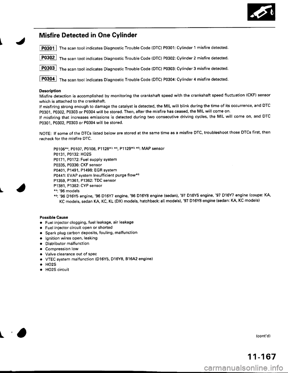
Misfire Detected in One Cylinder
P0301 | The scan tool indicates Diagnostic Trouble Code (DTC) P0301: Cylinder 1 misfire detected.
[F03O2l 16"""untool indicates Diagnostic Trouble code (DTc) P0302: Cylinder2 misfire detected.
[FO3Ofl 16" ".un toot indicates Diagnostic Troubte Code (DTC) P0303; Cylinder 3 misfire detected.
I P0304 I ths..rr tool indicates Diagnostic Trouble Code (DTC) PO3O4: Cylinder 4 misfire detected.
D€scription
lMisfire detection is accomplished by monitoring the crankshaft speed with the crankshaft speed fluctuation (CKF) sensor
which is attached to the crankshaft,
lf misfiring strong enough to damage the catalyst is detected, the MIL will blink during the time of its occurrence, and DTC
PO3O1, P0302, PO3O3 or P0304 will be stored. Then, after the misfire has ceased, the MIL will come on.
lf misfiring that increases emissions is detected during two consecutive driving cyclss, the MIL will come on, and DTC
P0301, P0302, P0303 or P0304 will be stored.
NOTE: lf some of the DTCS listed below are stored at the same time as a misfire DTC, troubleshoot those DTCS first, then
recheck for the misfire DTC.
PO106*1, P0107, P0108. P1128*3'*5, P1129*3'*5: MAP sensor
P0131, P0132: HO2S
P0171, P0172iFuel suppiy system
P0335, P0336: CKF sensor
P0401. P1491, P1498: EGR system
P0441: EVAP system Insufficient purge flow*6
Pl359. P1361. Pl362: TDC sensor
P1381. Pl382: CYP sensor*o: '96 models*6: '96 D16Y5 engine,'96 D16Y/ engine,'96 D16Y8 engine {sedan),'97 D16Y5 engine,'97 D16\4, engine (coupe: KA,
KC models, sedan KA. KC, KL (DX) models, hatchback:all models),'97 D16Y8 engine (sedan: KA, KC models)
Possible Cause
. Fuel injector clogging, fuel leakage, air leakage
. Fuel injector circuit open or shorted
. Spark plug carbon deposits, fouling, malfunction
. lgnition wires open. leaking
. Distributor malfunction
. ComDression low
. Valve clearance out of spec
. VTEC system malfunction (D16Y5, D16Y8. 81642 engine)
. HO2S
. HO2S circuit
(cont'd)
11-167
r'a
Page 1027 of 2189

22. Install the shift cable end on the control lever, and
install the shift cable on the shift cable bracket'
CAUTION: Take care not to bend the shift cable'
23. lnstall the clip in the direction shown.
LOCKNUT
SHIFI CABLE 29 N m {3.0 kg{ m, 22lblftl
SHIFT CABLEERACKET
WASHERIPLASTIC)
CONTROL LEVER
24, Connect the solenoid harness connector. the drive
pulley speed sensor connector. and the ground
cable terminals.
6x1.0mm12 N.m {1.2 kgf.m.8,7 rbtft)
GROUND CABLETERMINAL 6x1.0mm
GROUNDTERMINAL
12 N.m {1.2 kgf'm,8.7lbtfrl
DRIVE PULLEYSPEED SENSORCONNECTOR
SOLENOID HARNESS
CONNECTOR
25. Connect the starter motor cable on the starter motor.
and install the cable holder.
NOTE: When installing the staner motor cable. make
sure that the crimped side of the ring terminal is
facing out (see section 23).
STARTEB
BMOUNTING NUT
9 N.m (0.9 kgf m,7 lbf ft)
26. Install all removed connectors and clamps'
27. Install the distributor.
28. Install the intake air duct and air cleaner housing
29.
assemDly.
Refill the transmission with the recommended
Genuine Honda CVT Fluid (see page 14-2991
CAUTION: While filling the CvT Fluid, bs surs not io
allow dust and other fotoign particles to entor into
the transmission.
Connect the battery positive (+) terminal first, then
the negative (-l terminal to the battery'
Check the ignition timing (see section 23).
Start the engine. Set the parking brake, and shift the
transmission through all gears three times Check
shift cable adjustment (see page 14-355).
Check the front wheel alignment (see section 18)
Let the engine reach operating temperature (the
radiator fan comes on) with the transmission in lXl
or E position, then turn it off and check fluid level'
Perform the start clutch calibration procedure on
page 14-293.
Road test as described on pages 14-296 and 14-297
30.
31.
34.
36.
STARTER MOTOR
14-351