1996 HONDA CIVIC Heater radiator
[x] Cancel search: Heater radiatorPage 521 of 2189
Emission Gontrol System
System Description
The emission control system includes a Three Way Cata-lytic Convener (TWC), Exhaust Gas Recirculation (EGR)
system,. Positive Crankcase Ventilation (pCV) system andEvaporative Emission (EVAP) Control system. The emis-sion control system is designed to meet federal and stateemission standards.*: D16Y5 engine
Tailpipe Emission
Inspestion
@@ Do not smoke during ihis procedure. Keepany open flame away from your work area.
1. Start the engine. Hold the engine at 3,000 rpm withno load (in Park or neutral) until the radiator fancomes on. then let it idle.
2. Connect a tachometer.
Check and, if necessary, adjust the idle speed (see
page 11-220 - 223).
Warm up and calibrate the CO meter according to themeter manufacturer's instructions.
Check idle CO with the headlights, heater blower,rear window defogger, cooling fan, and air condition-er off.
NOTE: (Canada) Pull the parking brake lever up.Start the engine, then check that the headlights areoff.
CO mete. should indicate 0.1% maximum.
NOTE: '98 Dl6Y5 engine - lf the idle speed incress-es to 8101 50 rpm, this means the EVAp system ispurging the canister. To stop the purging temporari-ly. raise the engine speed above 1,000 rpm with theaccelerator pedal, then slowly release the pedal.
11-252
eFORWARD -
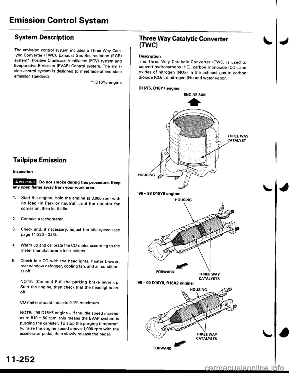
Three Way Catalytic Converter
(TWCI
Doscription
The Three Way Catalytic Converter (TWC) is used toconven hydrocarbons (HC), carbon monoxide (CO), andoxides of nitrogen (NOx) in the exhaust gas to carbondioxide (COr), dinitrogen (N,) and water vapor.
D15Y5, D16
, engine:
'99 - 00 D16Y8, 81642 engine:
ENGINE SIDE
t
Page 522 of 2189

\
lTo420l Th" """n toot indicates Diagnostic Troubte code (DTc) p0420: catatyst sysrem efficiency below threshold.
Description
This system evaluates the catalyst's capacity by means of the Ho2s {Primary and secondary) output during stable driving
conditions. ll deterioration has been detected during two consecutive driving cycles. the MIL comes on and DTC P0420 will
be stored.
NOTE: lf some of the DTCS tisted below are stored at the same time as DTC P0420, troubleshoot those DTCS first. then
recheck for DTC P0420
P0137, P0138: Secondary HO2S (Sensor 2)
Po14'1:Secondary H02S {Sensor 2) Heater
Possibl€ Cause
. TWC Deterioration
. Exhaust system leakage
Troubleshooting Flowchart
I
The MIL has been reported on.
DTC P0420 is stored
Problem verilication:1. Do the ECM/PCM Reset Proce
dure.2. Start the engine Hold the
engine at 3,000 rpm wath no
load {in Park or neutral) until
the radiator fan comes on.
3. Connect the SCS service con
4. Test drive 40 - 55 mph for
approx, two minutes Then
decelerate for at least 3 sec_
onds with the throttle com'pletely closed- Then reduce
the vehicle speed to 35 mph,
and try to hold it until the
readiness code comes on
Intermittent Iailure, system is OK
at this time.ls DTC P0420 indicated?
Check the TWC {see section 9l
lf necessary, replace the TwC
Page 970 of 2189
Start Clutch Control@
T
Start Clutch Calibration Procedure
NOTE: When the following parts are replaced, the TCM
must memorize the feedback signal for the start clutch
control.
. TCM
. Transmissionassembly
. Stan clutch assembly
. Lower valve bodv assembly
. Engine assembly or overhaul
'96 Model Only
CAUTION: Do not uso this procsdure on'97 - (X) mod-
els or you will damage the transmission. On '97 - 00
models, the TCM or PCM memorizes ths loodback sig'
nals when you drive the vehicle.
1. Engage the parking brake, and block the front
wheels securely.
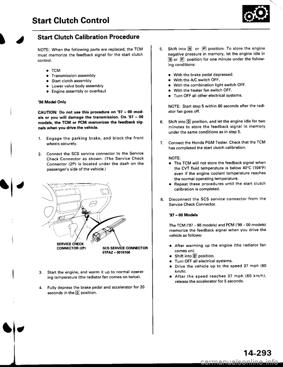
2. Connect the SCS service connector to the Service
Check Connector as shown. (The Service Check
connector (2P) is located under the dash on the
passenger's side of the vehicle.)
CONNECTOR07PAZ - lDl01(xt
Start the engine, and warm it up to normal operat-
ing temperature (the radiator fan comes on twice).
Fully depress the brake pedal and accelerator for 20
seconds in the E] position.
rl ,
CONNECTOR I2PI
14-293
7.
Shift into E o|. E position. To store the engine
negative pressure in memory. Iet the engine idle in
E or E position for one minute under the follow-
ing conditions:
. With the brake pedal depressed,
. with the y'\/c switch oFF.
. With the combination light switch OFF.
. With the heater fan switch OFF.
. Turn OFF all other electrical systems
NOTE: Start step 5 within 60 seconds after the radi-
ator fan goes off.
Shift into E position, and let the engine idle for two
minutes to store the feedback signal in memory
under the same conditions as in step 5.
Connect the Honda PGM Tester. Check that the TCM
has completed the start clutch calibration.
NOTE:
. The TCM will not store the feedback signal when
the CVT fluid temperature is below 40"C (104'F)
even if the engine coolant temperature reaches
the normal operating temperature.
. Repeat these procedures until the start clutch
calibration is completed-
Disconnect the SCS service connector from the
Service Check Connector.
'97 - 00 Models
The TCM ('97 - 98 models) and PCM ('99 - 00 models)
memorize the feedback signal when you drive the
vehicle as follows:
. After warming up the engine (the radiator fan
comes onl.
. Shift into E position.
. Turn OFF all electrical systems,
. Drive the vehicle up to the speed 37 mph (60
km/h).
. After the speed reaches 37 mph (60 km/h),
release the accelerator for 5 seconds.
Page 1413 of 2189
Heater Unit
Replacement
SRS components are located in this area. Review the
SRS component locations, precautions, and procedures
in the SRS section {24} before performing repairs or ser-
L Disconnect the negative cable from the battery.
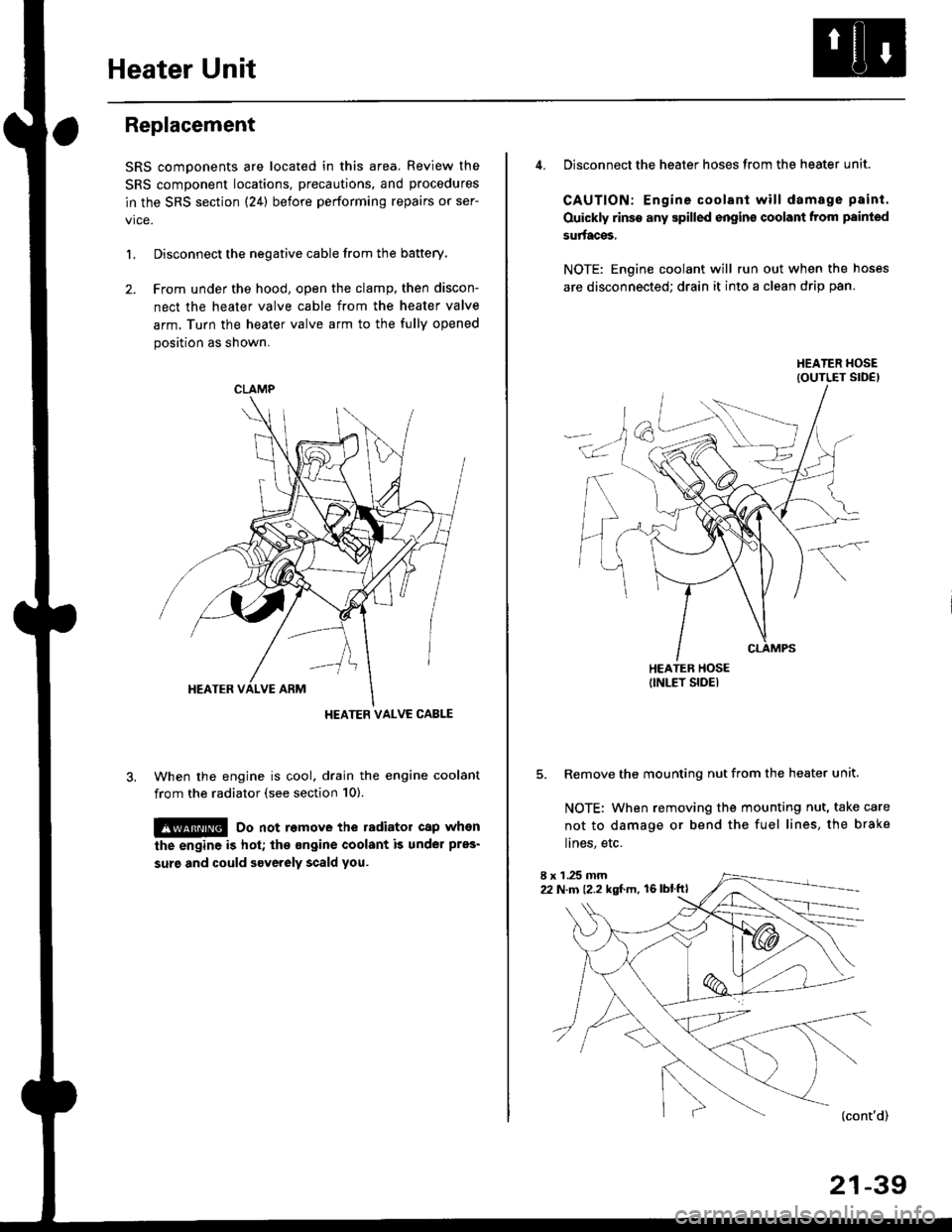
2. Frcm under the hood, open the clamp, then discon-
nect the heater valve cable from the heater valve
arm. Turn the heater valve arm to the fully opened
position as shown.
When the engine is cool. drain the engine coolant
from the radiator (see section 10).
!@ Do not remove the radiator cap when
the engine is hot; the ongine coolant is under pres'
surg and could severely scald you.
CLAMP
HEATER VALVC CABLE
4. Disconnect the heater hoses from the heater unit.
CAUTION: Engine coolant will damage p8int.
Ouickly rinse any spilled engins coolant from painted
su aces,
NOTE: Engine coolant will run out when the hoses
are disconnected; drain it into a clean drip pan.
5. Remove the mounting nut from the heater unit.
NOTE: When removing the mounting nut, take care
not to damage or bend the fuel lines, the brake
lines, etc.
I x 1 .25 mm22 N.m {2.2 kgl.m, 16lblftl
21-39
Page 1817 of 2189

Contents
How to Use This Manual ICircuit Schematics (see Circuit Index)Fuse/Relaylnformation 6Ground-to-Componentslndex 6-6ComponentLocationPhotooraohs 201Conriector Views 202
Circuit Index
Accessory power socket 155Air conditionerAir delivery'96198 models 61'99-'00 models 61-2Blower controls'96198 models 60'99100 models 60-1Compressor controls 62Fans 63Anti-lock brake system (ABS) 44A/T gear position indicatorCVT 89All except CVT 89-1Automatic transmission controlsAll '96-'98 models except CVT and GX 39All '99100 models except CVT 39-8All GX models 39-8'96-'�98 CVT 39-4'99100 cw 39-12Back-up lightsCoupe and Sedan 110Hatchback l'10-1Brake lightsAll Coupes and'96-'98 Sedans 110-15'99-'00 Sedans 110-16Hatchback 110-17Brake system indicator light'96198 models 7'1'99100 models 71-1Ceiling light 114-3Charging system 22Condenser fan 63Console lights 114Cruise control 34Dash lights 114Daytime running lights 110- 13Engine coolant temperature gauge 81-1Fog lights 110-10Front parking lights 110-2Fuel gauge 81-1Fuse/relay boxUnder-dash 6Under-hood 6-4Underhood ABS 6-3Gauges 81Ground distribution 14Ground-to-Componentslndex 6-6Hazard warning lightsAll except '99100 Sedans 110-6'99100 Sedans 110-8Headlights 110-12Headlight switch 100Heater - See Air ConditionerHorn'96197 models 40'98 model 40-1'99100 models 40-2lgnition key reminder 73lgnition systemAll '96198 models except Dl685 20All '99100 models except D16Y5 with Mn 2O-2All D1685 engines 20-2'99-'00 D 16Y5 with M/T 20
lndicators 80Integrated control unit 70lnterlock systemAll except'96J98 CVT 138'96198CVT 138-1License plate lightsAll Coupes and '96-'98 Sedans I l0-3'99100 Sedans 1 10-4Hatchback 110-5Low fuel indicator light 74Moonrool'96197 models |22'98-'00 models 122-1Odometer 81Oil pressure indicator light 80-3Power distributionBattery to ignition switch, fuses, and relaysFuses to relays and components 10-2Power door locksAll models without keyless entry 130'96-'98 models with keyless entry 130-2'99100 models with keyless entry 130-12Power mirrorsWithout detogger 141With defogger '141-2
Power windows 120Programmed fuel injection system (PGNr-Fl)All '96-98 models except D1685 23All '99-'00 models except D16Y5with M/T and D1685 24All D1685 engines 25'99100 D16Y5 with M/T 23Radiator fan 63Rear window defogger'96-,98 models 64'99100 models 64-1Seat belt reminder 73Security system'96.'98 USA HX, LX, EX 133'96-'98 Canada EX, Si 133'99TOO USA HX, LX, EX, DX.V Si 133-4'99100 Canada EX, Si 133-4All CX and DX models 133-8Speedometer 81Starting systemA./T (All except Dl685) 21A"/r (D16Bs) 21-1Manualtransmission 21-2Slereo sound system 150Supplemental rastraint system (SRS) 47Tachometer 81TailliqhtsAllboupes and'96-'98 Sedans 110-3'99100 Sedans 1 10-4Hatchback 110-5Trunk light 114-3Turn signal lightsAll except'99100 Sedans 110-6'99-'00 Sedans 1 10-8Vehicle speed sensor (VSS) 33Wiper/washerFront 91Rear 92
10
Page 1839 of 2189
Fuse
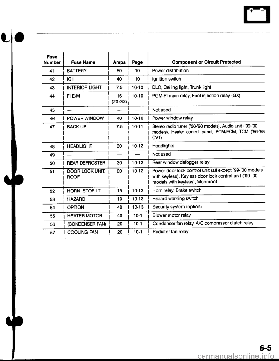
NumberFuse NameAmpsPage
BATTERY
Component or Circult Protected
Power distribution
lgnition switch
INTERIOR LIGHT | 7.5 | 10-10 | DLC, Ceiling light, Trunk light
FI E/M15 i(20 GX) i
i PGM-FI main relay, Fuel injection relay (GX)
Not used
POWER WINDOW| 10-10 | Power window relay
BACK UPStereo radio iuner ('9G'98 mod€ls), Audio unit ('99100
models), Heater control panel, PCM/ECM, TCM (9e'98
cvr)
HEADLIGHT
REAR DEFROSTER I
DOOR LOCK UNIT,
ROOF
i 10-12i Headlights
Not used
Rear window defogger relay
Power door lock control unit (all except '99-'00 models
with keyless), Keyless door lock control unit ('99-'00
models with keyless), Moonroof
i HORN, SrOP Lri 10-13i Horn relay, Brake switch
HAZARDHazard warning switch
OPTIONI 10-13I Security system (option)
i HEATER MOTOR Ii 10-1 i Blower motor relay
(CONDENSER FAN)
COOLING FANl1o-1
Condenser Jan relay, A'lC compressor clutch relay
Radiator tan relay
&5
Page 1961 of 2189
- How the Circuit Works
Radiator Fan
Voltage is provided at all times to the radiator fan
relay (contacts) through fuse 57. With the ignition
swilch in ON (ll), voltage is provided to the coil of
the relay through luse 17.
The radiator tan relay can be grounded through
either the engine coolant temperature switch or the
engine control module (ECM) or powertrain control
module (PCM).
The engine coolant temperature switch grounds
the radiator fan relay (coil) when the engine
coolant temperature exceeds 199'F (83'C). The
switch opens when coolanl temperature
decreases 3'- 8'C.
Condenser Fan
Voltage is provided at all times to the condenser fan
relay (contacts) through fuse 56. With the ignition
switch in ON (ll), voltage is provided to the coil of
the relay through fuse 17. When you push the A'lC
switch and put the heater fan switch in 1, 2,3, o( 4
position, the ly'C thermostat comes on, the
condenser fan relay energizes, and the condenser
fan motor runs.
A,/C Thermostat
The A,/C thermostat is located on the evaporator
housing. The A,/C thermostat tums off the A/C
compressor clutch if the temperature at the
evaporator goes below 3'C (37'F). This prevents
condensation from freezing on the evaporator fins
and blocking the air delivery into the passenger
compartment. lf the temperature goes below 3'C
(37"F) tuming off the Ay'C thermostat, ground will be
removed from the condenser fan relay. This will
deenergize the relay and remove voltage from the
condenser fan motor causing the fan to stop running.
Reter to the Service Manual (Section 23, Eleckical)
for specific tests or troubleshooting procedures.
63-3