Page 557 of 2189

Emission Control System
Evaporative Emission {EVAP) Controls (cont'dl
\J
tF1456-l
tP14sz-l
EVAPCONTROLCANISTERVENTSHUTVALVE
O.RINGReplace.
EVAPCONTROLCANISTER
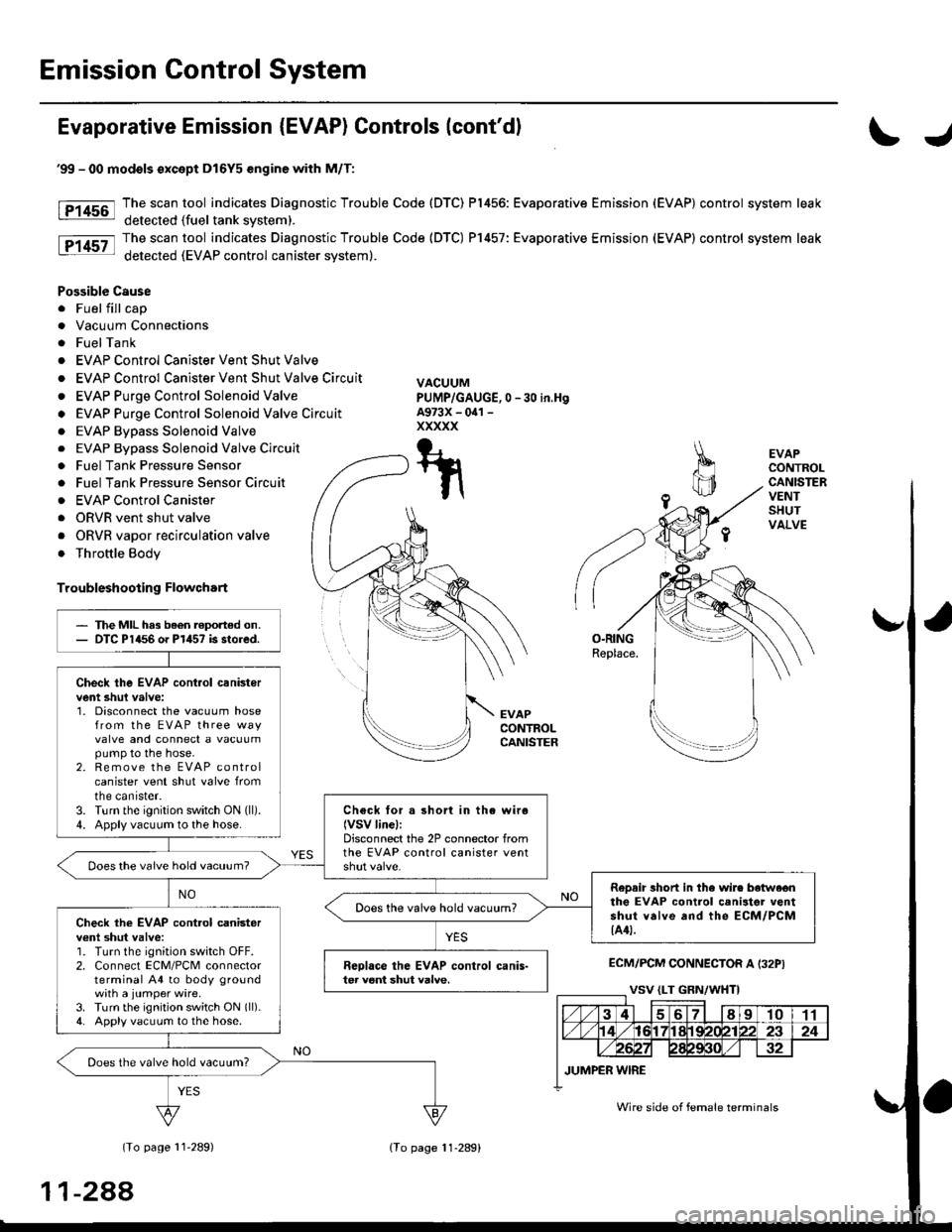
ECM/PCM CONNECTOR A I32PI
(To page 11'289)
'99 - 00 modols except Dl6Y5 engine with M/T:
The scan tool indicates Diagnostic Trouble Code (DTC) P1456: Evaporative Emission (EVAP) control system leak
detected (fuel tank svstem).
The scan tool indicates Diagnostic Trouble Code (DTC) P1457: Evaporative Emission (EVAP) control system leak
detected (EVAP control canister system).
Possible Cause
. Fuel fill cap
. Vacuum Connections
. FuelTank
. EVAP Control Canister Vent Shut Valve
. EVAP Control Canister Vent Shut Valve Circuit
. EVAP Purge Control Solenoid Valve
o EVAP Purge Control Solenoid Valve Circuit
. EVAP Bypass Solenoid Valve
0 -30 in,Hg
. EVAP Bypass Solenoid Valve Circuit
. Fuel Tank Pressure Sensor
. Fuel Tank Pressure Sensor Circuir
. EVAP Control Canister
. ORVR vent shut valve
. ORVR vapor recirculation valve
. Throttle Body
Troubleshooting Flowchart
VACUUMPUMP/GAUGE,A973X - oal -
xxxxx
T-t
t\
The MIL has been reported on.DTC P1456 o. P1457 is stored.
Check the EVAP cont.ol canistervent shul valve:1. Disconnect the vacuum hosefrom the EVAP three wayvalve and connect a vacuumpump to the hose.2. Remove the EVAP controlcanister vent shut valve fromtne canrster.3. Turn the ignition switch ON (ll).
4. Apply vacuum to the hose.Check for a short in the wiro(VSV linel:Disconnect the 2P connector fromthe EVAP control canister ventDoes the vaive hold vacuum?
RoDair 3hort in the wire botwe€nthe EVAP control canilter ventshut valve and the ECM/PCM{A4t.
Does the valve hold vacuum?Check the EVAP cont.ol canisterv€nl shut valve:1. Turn the ignition switch OFF.2. Connect ECM/PCM connectorterminal A4 to body groundwith a jumper wire.3. Turn the ignition switch ON (ll).
4. Apply vacuum to the hose.
Reolace the EVAP control canis-ter veni shut valve.
Does the valve hold vacuum?
Wire side of female terminals
11-288
lTo page 11-289)
Page 560 of 2189

IECM/PCM CONNECTOR
I
EVAP TWO WAYVALVE
Wire side oftemaleterminals
FUELTANK
(cont'd)
11-291
tn
VACUUMPUMP/GAUGE,0 - 30 in Hs
A973X - 041 -
xxxxx
(From page l1 290)
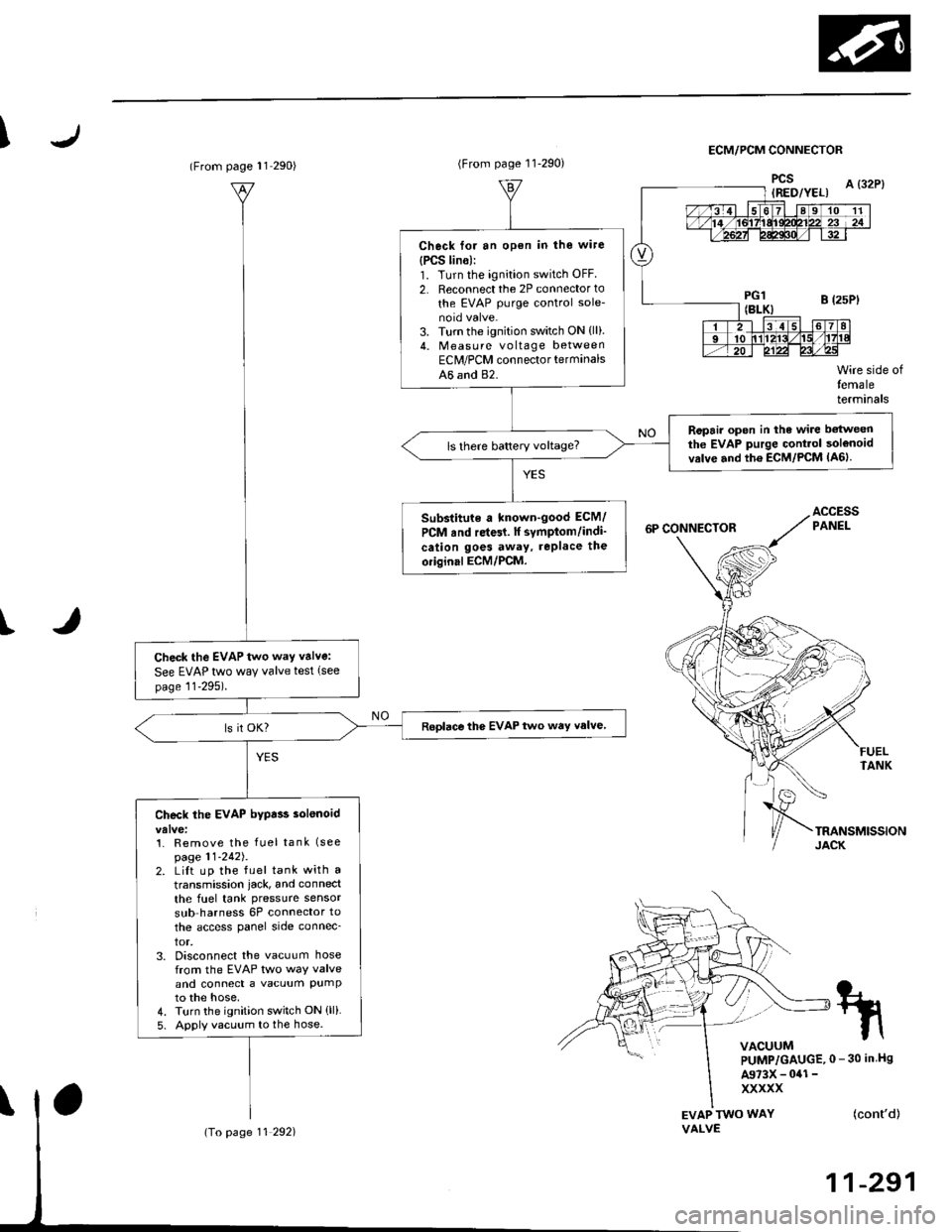
Check the EVAP two way valve:
See EVAP two way valve test (see
page 11-295).
Roplace the EVAP two way valve
Check the EVAP bypa$ solenoid
1. Remove the fuel tank (see
page 11-242J.2. LiIt up the fuel tank with a
transmission iack, and connect
the fuel tank pressure sensor
sub harness 6P connector to
the access panel side connec_
tor,3. Disconnect the vacuum hosefrom the EVAP two way valveand connect a vacuum PumPto the hose,4. Turn the ignition switch ON (ll)
5. Apply vacuum to the hose.
(To page 11 292)
(From page 11-290)
Check for an open in the wire
{PCS lin6):1. Turn the ignition switch OFF
2. Reconnect the 2P connector to
the EVAP purge control sole-
3. Turn the ignition switch ON {ll).4. Measu re voltage betweenEClr/PCM connector terminals
A6 and 82.
Ropair open in the wire betweenthe EVAP purge Gontrol solenoidvrlve and th6 ECM/PCM lA6lls there battery voltage?
Substitute a known-good ECM/
PCM rnd re{61. lf symptom/indi'
cation goes away, rePlace the
oiiginal ECM/PCM.
Page 565 of 2189

Emission Gontrol System
Evaporative Emission (EVAP) Controls (cont'dl
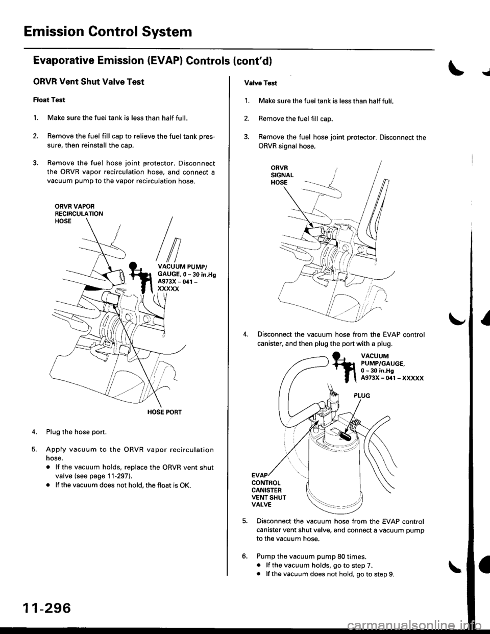
ORVR Vent Shut Valve Test
Float Test
1. Make sure the fuel tank is less than half full.
2. Remove the fuel fill cap to relieve the fuel tank pres-
sure, then reinstall the cap.
3. Remove the fuel hose joint protector. Disconnect
the ORVR vapor recirculation hose, and connect a
vacuum pump to the vapor recirculation hose.
ORVR VAPOERECIRCULATION
VACUUM PUMP/GAUGE,0 - 30 in.H9A973X - 041 -
xxxxx
Plug the hose port.
Apply vacuum to the ORVR vapor recirculation
nose.
. lf the vacuum holds, replace the ORVR vent shut
valve {see page 11-297).
. lf the vacuum does not hold, the float is OK.
4.
11-296
Vatve Tcst
1. Make sure the fueltank is lessthan halffull.
2. Remove the fuel fill cap.
3. Remove the fuel hose joint protector. Disconnect the
ORVR signal hose.
ORVRSIGNALHOSE
Disconnect the vacuum hose from the EVAP control
canister. and then plug the port with a plug.
VACUUMPUMP/GAUGE,0 - 30 in,HgA973X-041-XXXXX
CONTROLCANISTERVENT SHUTVALVE
Disconnect the vacuum hose from the EVAP control
canister vent shut valve, and connect a vacuum pump
to the vacuum hose,
Pump the vacuum pump 80 times.. lf the vacuum holds, go to step 7,. lf thevacuum does not hold, goto step9.
Page 566 of 2189
\
\
7. Connect a second vacuum pump to the OBVR signal
nose.
VACUUM PUMP/GAUGE.0 - 30 in.HgA973X - 041 -
xxxxx
Apply vacuum (1 pump) to the ORVR signal hose,
then check the vacuum on the pump in step 6.
. lf the vacuum holds, replace the ORVR vent shut
valve.
. lf the vacuum is released, the ORVR vent shut
valve is OK.
Disconnect the ORVR quick disconnect from the EVAP
canister, then plug the port on the canister.
Reapply vacuum (80 pumps).
. lf the vacuum holds, reDlace the ORVR vent shut
valve,
. lf the vacuum does not hold, inspect the EVAP can-
ister vent shut valve O-ring. lf the O-ring is OK,
replace the EVAP canister and repeat step 4.
\
I
11-297
ORVR Vent Shut Valve Replacement
1. Remove the fuel tank (see page 1 1-242).
2. Remove the ORVR vent shut valve from the fuel tank.
3. lnstall oarts in the reverse order of removal.
Page 568 of 2189
J
t
Clutch
Speciaf Tools .......... ...........12-2
f lfustrated Index .......... ......12-3
clutch Pedal
Adjustment .................... 12'4
Clutch Master Cylinder
Removal/lnstallation ..... 12-5
Slave Cylinder
Removal/lnstallation .....12'6
Pressure Plate
Removal/lnspection ...... 12-7
Clutch Disc
Removal/lnspection ...... 12-8
Flywheel
Inspection ....................... 12-9
Replacement ....................................... 12-9
Clutch Disc, Pressure Plate
lnstallation ..................... 12-10
Release Bearing
Removal/lnspection ......12-11
f nstalfation .................,... 12-12
\
Page 570 of 2189
lllustrated Index
\
NOTE:
. Whenever the transmission is removed, clean and grease the release bearing sliding surface
. lf the parts marked with an asterisk (*) are removed, the clutch hydraulic system mustbe bled (seepage 12-6)
. Inspect the hoses for damage, leaks, interference, and twisting
'RESERVOIF TANK
ASSIST SPRING
LOCK PIN
5x1,0mm9.8 N.m (1.0 kgf.m,7.2 tbtftl*CLUTCH LINE15 N.m {1.5 kgJ m,11 tbt.ft)
RELEASE BEARINGRemoval/lnspection, page 12-1 1Installation, page 12-'12
*CLUTCH MASTER CYLINDERRemoval/lnstallation, page 12 5
6x1.0mm9.8 N.m (1.0 kgf.m,7.2 tbf.ft)
FLYWHEELInspectaon, page 12IReplacement, Page 12-9
CLUTCH DISCRemoval/lnspection, page 1 2-8
lnstallation, page 12-'10
'12 x 1.0 mm118 N.m {12.0 kgt'm,86.8lbfft)
PBESSURE PLATEBemoval/lnspection, page 12 7Installation, page 12''10
8 x 1.25 mm22 N m (2.2 kgf.m, 16lbf ft)
ISLAVE CYLINDERRemoval/lnstallation, page 12_6
12-3
Page 574 of 2189

Pressure Plate
\Removal/lnsPection
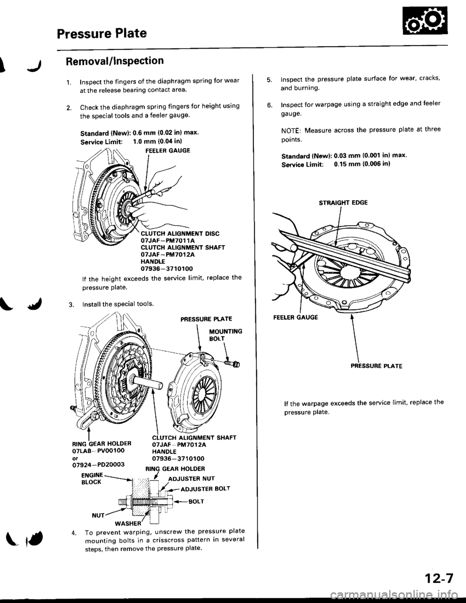
1.Inspect the fingers of the diaphragm spring for wear
at the release bearing contact area.
Check the diaphragm spring fingers for height using
the special tools and a feeler gauge.
Standard {New}: 0.6 mm (0.02 inl max.
Seruice Limit: 1.0 mm {0.04 in}
FEELER GAUGE
CLUTCH ALIGNMENT DISCOTJAF_PM7O1 1ACLUTCH ALIGNMENT SHAFTOTJAF-PM7012AHANDLE07936-37tOtOO
lf the height exceeds the service limit, replace the
pressure Plate.
3. Installthe special tools
PRESSURE PLATE
MOUNTINGBOLT
ALIGNMENT SHAFTOTJAF-PM7012AHANDLE07936-371010Oo7924-PD20003GEAR HOLDER
07LA8-PVOOIOOot
ENGINEBLOCKADJUSTER BOLT
BOLT
4. To prevent warping, unscrew the pressure plate
mounting bolts in a crisscross pattern in several
steps, then remove the pressure plate.
f
12-7
lnspect the pressure plate surface for wear' cracks,
and burning.
Inspect for warpage using a straight edge and leeler
ga uge.
NOTEr Measure across the pressure plate at three
pornrs.
Standard (Newl: 0.03 mm (0.001 inl max.
Service Limit: 0.15 mm (0.006 inl
lf the warpage exceeds the service limit, replace the
pressure plate.
STBAIGHT EDGE
Page 575 of 2189
Clutch Disc
RemovaUlnspection
2.
'1. Remove the clutch disc and special tools.
CLUTCH
CLUTCH ALIGNMENT SHAFToTJAF-pM7012A xltori07936-3710100
Inspect lining of the clutch disc for signs of slipping
or oil. lf it is burned black or oil soaked, replace it.
Measure the clutch disc thickness.
Clulch Disc Thickness:
Standard (Now): 8.5 - 9.1 mm (0.33 - 0.36 in)
Servic€ Limit: 5.5 mm (0.22 inl
CLUTCH
lf the thickness is less than the service limit. .eolacethe clutch disc.
12-8
U
4. Measure the depth from the lining surface to therivets, on both sides.
Rivet Depth:
Standard lNewl: 1.3 - 1.9 mm {0.05 - 0.07 in} min.
Service Limit: 0.2 mm (0.01 in)
lf the depth is less than the service limit, replace the
clutch disc.
CLUTCH DISC