Page 603 of 2189

Inspection
1.surfaces lor
countershaftInspect the gear surfaces and bearang
wear and damage, then measure tne
at points A, B, and C.
Standard: A: 30.000 - 30.015 mm
(1.1811- 1.1817 inl
B: 35.984 - 36.000 mm
(1.i1167 - 1.4173 inl
C: 24.980 - 2i1.993 mm
{0.9835 - 0.9840 in)
Seryice Limit: A: 29.950 mm (1.1791 inl
B: 35.930 mm (1 '1146 in)
C: 24.930 mm 10.9815 in)
Check oil passages
for cloggrng-
ICheck for wearano oamage.
. lf any part of the countershaft is less than
service limit, replace it with a new one.
Inspect for runout.
Standard: 0.02 mm (0.001 inl max.
Seryice Limit: 0.05 mm {0'002 in)
. lf the runout is more than the service limit. replace
the countershaft with a new one.
the
2.
t,3. Install the parts on the countershait
Reassembly
CAUTION:
. Press the 3rd,4th, and sth gears on the countershaft
without lubrication.
. When installing the 3rd. 4th, and 5th geals, support
the shaft on steel blocks and installthe gears using a
pless.
NOTE: Reler to page 13-20 for reassembly sequence'
1. lnstall the needle bearing on the countershaft'
, 36x41 x 25.5mmNEEDLE BEARING
COUNTERSHAFT
2. Assemble the pans below as shown.
NOTE: Check that the fingers of the friction damper
are securely set in the grooves of the 1sv2nd syn-
chro hub.
2ND GEAR
39x/+4x27mmNEEDLE BEARING
SPACER COLLAR
FRICTION DAMPER
SYNCHRO RING
SYNCHRO SPRING
REVERSE GEAR
lST/2NOSYNCHRO HUB
SYNCHRO SPRING
SYNCHRO RING
FRICTION DAMPER
1ST GEAR
(cont'd)
13-23
Page 606 of 2189

Shift Fork Assembly
Clearance Inspection
NOTE: The synchro sleeve and the synchro hub shouldbe replaced as a set.
l. Measure the clearance between each shift fork andits matching synchro sleeve.
Standard: 0.35 - 0.65 mm {0.014 - 0.026 intService Limit 1.0 mm (0.04 in)
2. lf the clearance is more than the service limit, mea-
sure the thickness of the shift fork fingers.
Standard:
3rd/ilth: 7.il - 7.6 mm {0.291 - 0.299 in}lst/2nd, 5th: 6.2 - 6.il mm (O.2,tt - 0.252 in)
lf the thickness of the shift fork finge.s is notwithin the standard, replace the shift fork with anew one.
lf the thickness of the shift fork fingers is withinthe standard. replace the synchro sleeve with a
SHIFT FORK
13-26
J
3. Measure the clearance between the shift piece orshift fork and the shift arm B.
Standard: 0.2 - 0.5 mm {0.008 - 0.02 in}
Sarvice Limit: 0.62 mm 10.0244 inl
4. lf the clearance is more than the service limit, mea-sure the groove of the shift piece or shift fork,
Standard: 13.2 - 13.4 mm (0.520 - 0.b28 inl
lf the groove of the shift piece or shift fork is notwithin the standard, replace the shift piece orshift fork with a new one.
lf the groove of the shift piece or shift fork iswithin the standard, replace the shift arm B witha new one.
\J
Page 607 of 2189
Synchro Sleeve,
Synchro Hub
MBS Shift Piece InsPection
1. Measure the width of the MBS shift piece.
Standard; 6.9 - 7.1 mm 10 272 - 0.280 inl
Service Limit: 6.8 mm {0.268 inl
lf the width of the MBS shift piece is less than
service limit, replace the MBS shift piece'
t
I nspection/l nstallati on
'1.lnspect gear teeth on all synchro hubs and synchro
sleeves tor rounded off corners, which indicate
Install each synchro hub in its mating synchro
sleeve, and check for freedom of movement.
NOTE: lf replacement is required, always replace
the synchro sleeve and synchro hub as a set.
SYNCHROSLEEVE
When assembling the synchro sleeve and synchro
hub, be sure to match the three sets of longer teeth
(120 degrees apart) on the synchro sleeve with the
three sets of deeper grooves in the synchro Hub
CAUTION: Do not install th€ sYnchro sleeve with
its longsr t€sth in the synchro hub slots bocause ii
will damage ths spring ring.
LONGER TEETH
13-27
Page 608 of 2189

Synchro Ring, Gear
Inspection
1. Inspect the synchro ring and gear.
A: Inspect the inside of the synchro ring for wear.
B: Inspect the synchro sleeve teeth and matching
teeth on the synchro ring for wear (rounded off).
r- /-\
oioi *-o*
C: Inspect the synchro sleeve teeth and matching
teeth on the gear for wear (rounded off).
,
UtJGOOO WORN
D: Inspect the gear hub thrust surface for wear.
E: Inspect the cone surface for wear and roughness.
Fr Inspect the teeth on all gears for uneven wear,
scoring, galling, and cracks.
2. Coat the cone surface of the gear with oil. and place
the synchro ring on the matching gear. Rotate the
synchro ring. making sure that it does not slip.
Measure the clearance between the synchro ring
and gear all the way around.
NOTE: Hold the synchro ring against the gear evenly
while measuring the clearance.
Synchro Ring-to-Gear Clearance
Standard: 0.73 - 1.18 mm {0.029 - 0.046 in}
Service Limit 0.4 mm {0.02 in)
lf the clearance is less than the service limit, replace
the synchro ring and synchro cone.
SYNCHRO
SYNCHRO
\a
r/
13-28
Page 609 of 2189

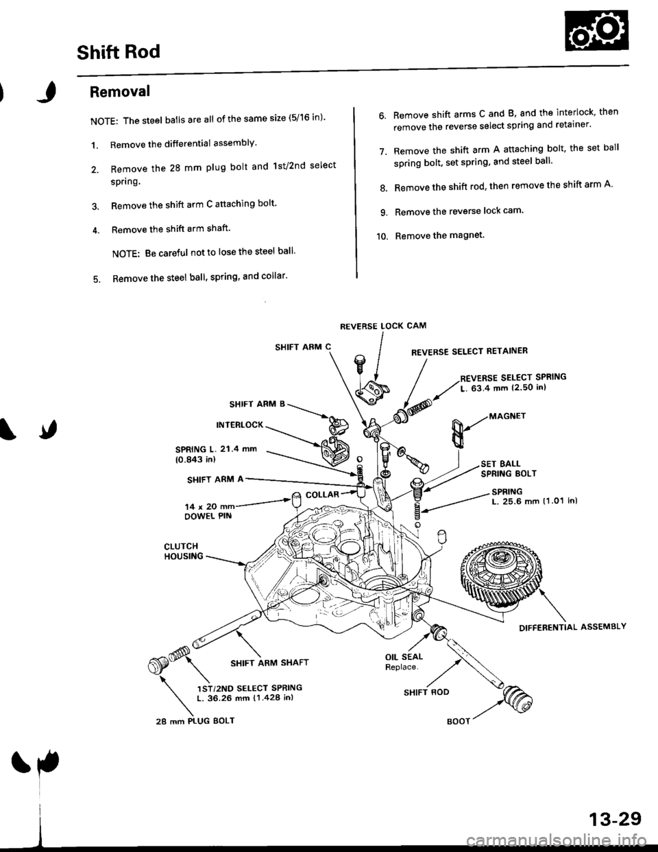
Shift Rod
Removal
NOTE: The steel batlsareall of the same size (5/16 in)'
1. Remove the differential assembly'
2. Remove the 28 mm plug bolt and lst/2nd select
spring.
3. Remove the shift arm C attaching bolt'
4. Remove the shift arm shaft'
NOTE: Be careful notto lose the steel ball'
5. Remove the steel ball, spring, and collar'
SHIFT ARM C
SHIFT ARM B
INTERLOCK
6. Remove shift arms C and B, and the interlock, then
remove the reverse select spring and retainer'
7. Remove the shift arm A attaching bolt, the set ball
spring bolt, set spring, and steel ball'
8. Remove the shift rod' then remove the shift arm A'
9. Remove the reverse lock cam'
10. Remove the magnet.
CAM
REVERSE SELECT RETAINER
REVERSE SELECT SPRING
L. 63.4 mm {2.50 inl
REVERSE LOCK
lIV/
' lJ
\s
SPRING L. 21.4 mm(0.843 in)
SI{IFT ARM A
14x20OOWEL PIN
COLLAR
,*(S* \
6S* srtrr ran,t srarr
\
',)r,r"o r..."r "rr,*n
t. 36.26 mm {1.428 in,
28 mm PI-UG BOLT
OIL SEALReplace.
&-"onn"
BALLSPRING EOLT
SPRINGL. 25.6 mm 11.01 inl
DIFFERENTIAL ASSEMBLY
SHIFT ROD
Page 611 of 2189
I
Bearing RePlacement
NOTE: Check bearings for wear and rough rotation lf
the bearings are OK, removal is not necessary'
'1. Remove the ball bearings using a bearing puller as
shown.
EALL B€ARING
lnstall new ball bearings using the special tool as
shown.
NOTE: Drive the bearings squarely until they bot-
tom against the carrler.
DRIVER, 40 mm LD.?746 -0030100
\1,
Final Driven Gear RePlacement
1, Remove the bolts in a crisscross pattern in several
steps, then remove the final driven gear from the
ditferential carrier'
NOTE: The final driven gear bolts have left-hand
threads.
10 x 1.0 mm BOLT
1o1 N.m llO.3 kgf'm,74 5lbf'ft)
Lelt'hand threads
lnstall the final driven gear by tightening the bolts
in a crisscross pattern in several steps'
Page 613 of 2189

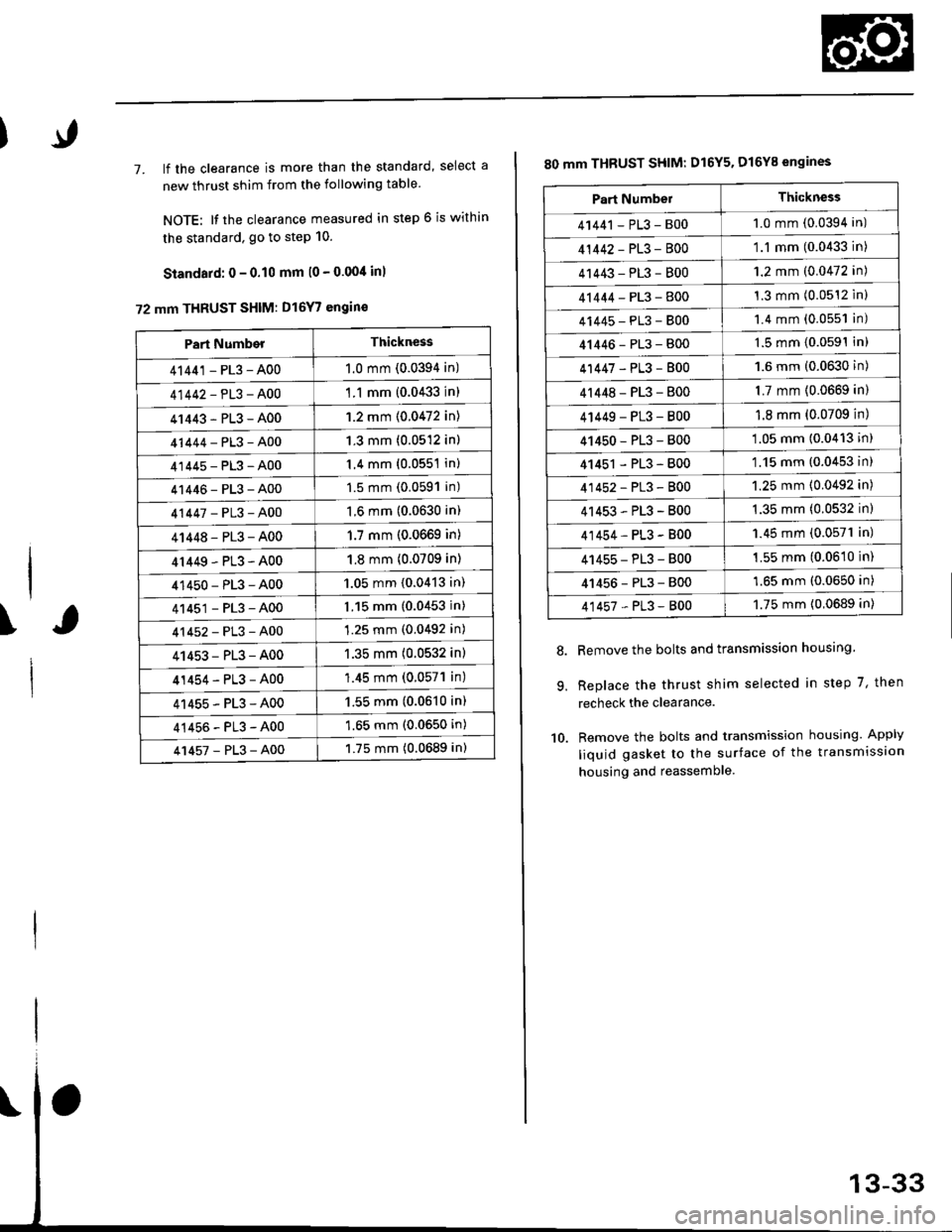
7. lf the clearance is more than the standard, select a
new thrust shim from the following table
NOTE: It the clearance measured in step 6 is within
the standard. go to step 10.
Standard: 0 - 0.10 mm l0 - 0.00/t inl
72 mm THRUST SHIM: D16Y7 engin€
\
Part NumberThickness
41441 - PL3 - A001.0 mm (0.0394 in)
41442-PL3-A00'1 .1 mm {0.0433 in)
41443-PL3-A001.2 mm {0.0472 in)
41444-PL3-A001.3 mm (0.0512 in)
41445-PL3-A001.4 mm (0.0551 in)
41446-PL3-A001.5 mm (0.0591 in)
41447-PL3-A001.6 mm (0.0630 in)
41448-PL3-A001.7 mm (0.0669 in)
4r449-PL3-A001.8 mm (0.0709 in)
41450-PL3-A001.05 mm {0.0413 in)
41451-PL3-A001.15 mm (0.0453 in)
41452-PL3-A001.25 mm (0.0492 in)
41453-PL3-A001.35 mm (0.0532 in)
41454-PL3-A00'1.45 mm (0.057'l in)
41455-PL3-A001.55 mm (0.0610 in)
41456-PL3-A001.65 mm (0.0650 in)
41457-PL3-A001.75 mm (0.0689 in)
80 mm THBUST SHIM: D16Y5. D16Y8 engines
Remove the bolts and transmission housing.
Replace the thrust shim selected in step 7, then
recheck the clearance.
Remove the bolts and transmission housing. Apply
liquid gasket to the surface of the transmission
housing and reassemble
8.
9.
10.
Part NumbelThickness
41441 - PL3 - B001.0 mm (0.0394 in)
41442-PL3-8001.1 mm (0.0433 in)
41443-PL3-8001.2 mm (0.0472 in)
41444-PL3-8001.3 mm (0.0512 inl
41445-PL3-8001.4 mm (0.0551 in)
41446-PL3-8001.5 mm (0.0591In)
41447-PL3-8001.6 mm (0.0630 in)
4r 448 - PL3 - 8001.7 mm (0.0669 in)
4 t449 - PL3 - 8001.8 mm (0.0709 in)
41450-PL3-800'1.05 mm (0.0413 in)
41451 - PL3 - 800'1.15 mm (0.0453 in)
41452-PL3-8001.25 mm (0.0492 in)
41453-PL3-B001.35 mm (0.0532 in)
41454-PL3-B001.45 mm (0.0571 in)
41455-PL3-B001.55 mm (0.0610 in)
41456-PL3-8001.65 mm (0.0650 in)
41457-PL3-8001.75 mm {0.0689 in)
Page 614 of 2189
Clutch Housing Bearing
Replacement
Mainshaft
1. Remove the ball
shown.
bearing using the special tool as
3i8 " -16 SLIDE HAMMER(Commercially available)
ADJUSTAELE BEARINGPULLER, 25-40 mm07736-AO10004
2, Remove the oil seal from the clutch housing,
CLUTCH
Replace.
13-34
l.
3, Drive the new oil seal into the clutch housing usingthe specialtools as shown.
ATTACI{MENT, 42 x 47 mm07746 -0010300
CLUTCHHOUSING
Drive the ball bearing into the clutch housing usingthe special tools as shown.
ATTACHMENT, 52 x 55 mm DRIVER07746 001040007749-0010000
t./
07749 -0010000