Page 473 of 2189

ldle Gontrol System
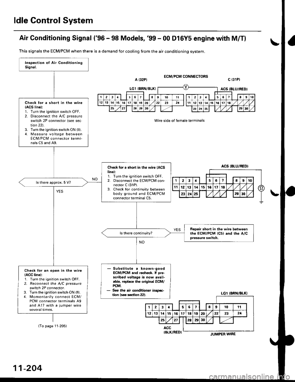
Air Gonditioning Signal ('96 - 98 Models, '99 - 00 Dl6Y5 engine with M/Tl
a {32P1ECM/PCM CONNECTORS
Wire side of female terminals
c l3lPl
This sjgnals the ECM/PCM when there is a demand for cooling from the air conditioning system.
(To page 11-205)
Check for a short in the wire{ACS line):1. Turn the ignition switch OFF.2. Disconnect the A/C pressure
switch 2P connector {see section 22).3. Turn the ignition switch ON (ll).
4. Measure vo lta ge betweenECM/PCM connector termi-nals C5 and A9.
Check for a .hort in the wi.e {ACSline):1. Turn the ignition switch OFF.2. Disconnect the ECM/PCM con-nector C (3lPi.
3. Check tor continuity betweenbody ground and ECM/PCMconnector terminal C5,
ls there approx. 5 V?
Reotir short in the wi.e betweenthe ECM/PCM lc5l and rhe A/Cpressure switch.
ls there continuity?
- Substitute a known-goodECM/rcM .nd re.fieck. f Dre-scribed voltage is now availtble, replace the original ECft4/PCM,- See the air conditioner inspe-tion ls€e s€ction 221.
Check tor an op€n in the wireIACC lin6l:1. Turn the ignition switch OFF.2. Reconnect the A/C pressure
switch 2P connector.3. Turn the ignition switch ON (ll).
4. Momentarily connect ECM/PCM connector terminals A9and A17 with a jumper wire
LGl IBRN/8LKIACS {BLU/RED)
2361I9't0Itt3a89t0
12't31al5l617t8t920232all12l3l!ai5!617'tE
252l2A2930232a252930
ACS (BLU/BEDI
LGl IBRN/BLKI
123aslslrl lolgl ro lrr I
121314l516y)nltslnl/@) zr I zr I
25271!M1 1-/r
ACC
11-204
IBLK/RED)JUMPER WIRE
Page 479 of 2189

ldle Control System
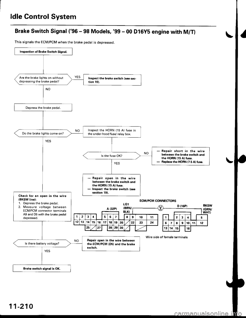
Brake Switch Signal ('96 - 98 Models, '99 - 00 Dl6YS engine with M/Tl
This signals the ECM/PCM when the brake pedal is deoressed.
LGlBKSW(GRN/WHTI
D {16P)
Wire side of female t€rminals
Inspection of Brake Switch Signal.
Are the brake lights on withoutdepressing the brake pedal?
Depress the brake pedal.
Inspect the HORN (15 A) fuse inthe under-hood fuse/ relay box.Do the brake lights come on?
- Repair short in the wirebetween the brake 3whch andrhe HORN 115 At lu3e.- Replace the I|oRN 17.5 A) tus€.
Repair open in the wirebetween the brake switch andthe HORN 115 Al fuse.Inspect th6 br.ke switch {s6€section l9l.Check tor an open in the wireIBKSW line):1. Oepress the brake pedal.2. Measure voltage betweenECM/PCNI connector terminalsAg and D5 with the brake pedaloepresseo.
Repair open in the wire b€tweenthe ECM/PCM {Dsl and the brakeswitch.
ls there battery voltage?
Brakc switch sign.l is OK.
ECM/PCM CONNECTOFS
A (32PtIBRI\v
,la678101112I
121311151617t8192022232aI9101112
25212Aa3013141516
11-210
Page 482 of 2189
t
(From page 11 212)
Check lor a 3hort in the PSP
switch:1. Turn the ignition switch OFF.
2. Disconnect the 2P connector
from the PSP switch.
3. Turn the ignition switch ON (ll)
4. Measure voltage between
ECM/PCM connector termi-
nals Ag and C16.
Check tor a short in the wiro {PSP
SW linel:'1. Turn the ignition switch OFF.
2. Disconnect the ECM/PCM con
nector C (31P).
3. Check lor continuity between
body ground and ECM/PCM
connector terminal C16.
ls there battery vohage?
Repair ahort in the wire between
the ECM/PCM (C16) and th6 PsP
switch.
Substitute a known_good ECM/
PCM end rechock. lf Prescribedvoltage b now avsilable. rePlace
the original ECM/PCM.
ECM/PCM CONNECTORS
Wire side of temale terminals
'l
12a6189t0
tl12131415161718
232125a30
oPSP SW (GRNI
1-213
Page 485 of 2189

ldle Control System
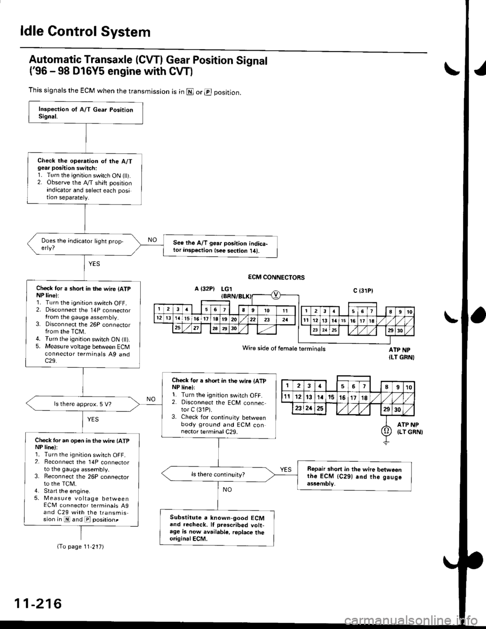
Automatic Transaxle (CVTI Gear Position Signal
('96 -98 D16Y5 engine with CW)
ATP NP{LT GRNI
INP
GBN)
This signals the ECM when the transmission is in @ or @ position.
Check the operation oI the A/Tgear position switch:1. Turn the ignition switch ON flt).2. Observe the A/T shift positionindicator and select each position separately.
See lhe A/T gear position indica-tor insp€ction {see sec{ion l/tl.
Check tor a short in the wir6 (ATpNP line):1. Turn the ignition switch OFF.2. Disconnect the 14P connectorIrom the gauge assembly.3. Disconnect the 26P connectorfrom the TCM.4. Turn the ignition switch ON fll).5. Measure voltage between ECMconnector terminals A9 andc29.
Check for a short in the wire lATpNP linell1. Turn the ignition switch OFF.2. Disconnect the ECM connector C (31P).
3. Check for continuity betweenbody ground and ECM connector terminal C29.
ls there approx. 5 V?
Check for an open in the wire lATpNP lina):1. Turn the ignition switch OFF_2. Beconnect the 14P connectorto the gauge assembly.3. Reconnect the 26P connectorto the TCM.4. Sta rt the engine.5. Measure voltage betweenECM connector terminals A9and C29 with the transmission in E and E posationt
Repair short in the wire betweenthe ECM {C291 and the gaugeassemblv,
Substitute a known-good ECMand recheck. lf prescribed volt-age is now avrilable, replace theo.iginalECM.
Wire side ot female terminals
2457I910
t112131a15151718
2321252930
ATP(LT io
(To page 11'217)
11-216
Page 493 of 2189
Fuel Supply System
Fuel Lines
NoTE: Check fuel system lines, hoses, fuel filter, and other components lor damage, leaks and deterioration, and replaceif necessary.
(2.2 kgt.m, 16lbf.ft)(D16Y5 engine: 28 N.m2.8 kgtm, 21 lbf ft)
The illustrationshows'99 00 models.
t/
,ee.- ;
4/
/.,/
Tl...,.' ..4,/
i,/
I
22 N.m
11-224
Page 494 of 2189
I'96 - 98 models:
NOTE: Check all hose clamps and retighten if necessarY.
M
/vFUELFILTER
PRESSUREREGULATOR
IFUELTANKFUELGAUGESENDINGUNITBASE GASKETReplace.
Clamp In rhe middle
@
Clamp in the middle
10-14mm(0.39 - 0.55 inl
(cont'd)
11-225
Page 496 of 2189

I
Fuel Tube/Ouick-Gonnect Fittings
Precautions
!@ Do not smoke while working on the fuel
system, Keep open flames away from your work a.ea'
The fuel tube/quick-connect fittings assembly connects
the in tank fuel pump with the fuel feed pipe. For remov-
ing or installing the fuel pump and fuel tank, it is neces-
sary to disconnect or connect the quick-connect fittings.
Pay attention to lollowing:
. The fuel tube/quick-connect fittings assembly is not
heat-resistant; be careful not to damage it during
welding or other heat-generating procedures
. The fuel tube/quick-connect fittings assembly is not
acid-proof; do not touch it with a shop towel which
was used for wiping battery electrolyte. Replace the
fuel tube/quick-connect fitlings assembly if it came
into contact with electrolyte or something similar.
. When connecting or disconnecting the fuel tube/
quick connect liltings assembly, be careful not to
bend or twist it excessively. Replace it if damaged
A disconnected quick-connect fitting can be reconnecled,
but the retainer on the mating pipe cannot be reused
once it has been removed from the pipe. Replace the
retatner wnen
. Replacing the fuel pump.
. Replacing the fuel leed pipe.
. lt has been removed lrom the PiPe.. lt is damaged.
ACCESS PANEL
I
Disconnestion
!@ Do not smoke while working on the luel
system. Keep open llames away lrom youl work area.
1. Relieve fuel pressure (see pages 11'230,2311.
2. Check the tuel quick-connect tittings for dirt, and
clean if necessary.
3. Hold the connector with one hand and press down
the retainer tabs with the other hand, then pull the
connector off.
NOTE:
o Be carelul not to damage the pipe or other pans
Do not use tools.
. lf the connector does not move, keep the retainer
tabs pressed down, and alternately pull and push
the connector until it comes off easily.
. Do not remove the retainer from the pape; once
removed, the retainer must be replaced with a
new one.
LOCKING PAWL
BETAINER TAB
CONNECTOR
Check the contact area o{ the pipe for dirt and dam-
age.
. lf the surface ls dirty, clean it.
. lf the surface is rusty or damaged, replace the
fuel pump or fuel feed piPe.
4.
(cont'd)
11-227
PIPE
Page 499 of 2189

Fuel Supply System
System Description
The fuel supply system consists of a fuel tank, in-tank
high pressure fuel pump, PGM-FI main relay, fuelfilter,
fuel pressure regulator, fuel injectors. and fuel delivery
and return lines. This system delivers pressure-regu-
lated fuel to the fuel injectors and cuts the fuel delivery
when the engine is not running.
Fuel Pressure l'96 Modelsl
Relieving
Before disconnecting fuel pipes or hoses, release pres-
sure from the system by loosening the 6 mm service
bolt on top of the fuel filter.
. Do not smoke whil6 working on the fuel system.
Kgsp opon flames or sparks away from youl work
area.
. Be sure to relieve fuel pressure while the ignition
switch is off.
1. Write down the frequencies for the radio's preset
buttons.
2. Disconnect the battery negative cable from the bat-
tery negative terminal.
3. Remove the fuelfill cap,
4. Use a box end wrench on the 6 mm service bolt at
the fuel filter while holding the special banjo bolt
with another wrench,
5. Place a rag or shop towel over the 6 mm service bolt.
6, Slowly loosen the 6 mm service bolt one complete
rurn.
. A fuel pressure gauge can be attached at the 6 mm
service bolt hole.
. Always reDlace the washer between the service
bolt and the special banjo bolt whenever the ser-
vice bolt is loosened.
. Replace all washers whenever the bolts are
removeo.
11-230
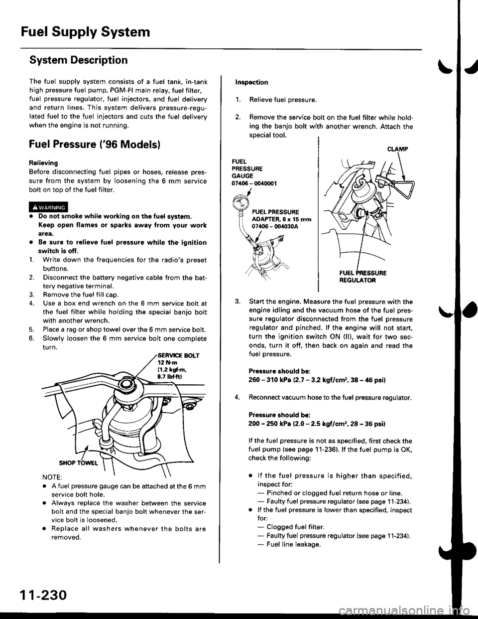
Inspoction
1. Relieve fuel pressure.
2. Remove the service bolt on the fuel filter while hold-
ing the banjo bolt with another wrench. Attach the
special tool.
FUELPRESSUREGAUGE07406 - 00ir0(x)1
Start the engine. Measure the fuel pressure with the
engine idling and the vacuum hose of the fuel pres-
sure regulator disconnected from the fuel pressure
regulator and pinched. lf the engine will not start,
turn the ignition switch ON (ll), wait for two sec-
onds, turn it off, then back on again and read the
fuel pressure.
Pr€3sure should bo:
260 - 310 kPa (2.7 - 3.2 kgt/cmr, 38 - 46 psi)
Reconnect vacuum hose to the fuel pressure regulator,
Pressure should bo:
200 - 25O kPa l2.O - 2.5 kgf/cm'�, 28 - 36 psil
lf the fuel pressure is not as specified, first check the
fuel pump {see page 11-2361. lf the fuel pump is OK,
check the following:
. lf the fuel pressure is higher than specified,
inspect for;- Pinched or clogged fuel return hose or line.- Faulty fuel pressure regulator (see page 11-234).. lf the fuel pressure is lower than specified, inspect
for:- Clogged fuelfilter.- Faulty fuel pressure regulator {see page 11-234).- Fuel line leakage.
REGULATOB