Page 160 of 2189
Special Tools
(\
Ref. No. I Tool NumberDescriptionOty Page Relerence
q oTHAH PJ7010B
g I 07JAA-001020A
g I 07JAB-0010204
I 07JAB - 0010404
g 07LAJ - PR3020A
|6) 07MAA - PR70100
g I ozvu,r - enu orzo
g 07MAF - PR9010A
g 07742 - 0010100(!D I 07757-PJ10104
Valve Guide Reamer,5.5 mm
Socket, 19 mm
Holder Handle
Pulley Holder Attachment. 50 mm
Air Stopper
Tappet Adjuster
Tappet Locknut Wrench
Valve Spring Compressor Attachment ExtensionValve Guide Driver, 5.5 mm
Valve Spring Compressor Attachment
1 I 6-81
1 659
1 6-59
1 ] 6-5s
1 I 6-55
1 6-57
1 6-57
1 J 6-77
1 6-80, 81
1 6-71
ta;
aL)'n
-=<-,,LE;;
(D
a
6-50
\-
Page 165 of 2189

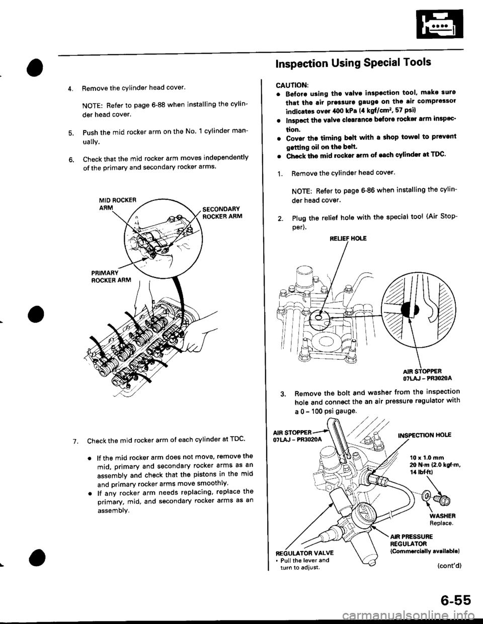
Remove the cylinder head cover.
NOTE: Refer to page 6-88 when installing the cylin-
der head cover.
Push the mid rocker arm on the No. 1 cylinder man-
ually.
Check that the mid rocker arm moves independently
of the primary and secondary rocker arms.
Check the mid rocker arm ot each cylinder at TDC'
. lf the mid rocker arm does not move, removs the
mid, primary and secondary rocker arms as an
assembly and check that the pistons in the mid
and primary rocker arms move smoothly.
. lf any rocker arm needs replacing, replace the
primary. mid, and secondary rocker arms as an
assembly.
7.
2. Plug the
per).
Inspection Using SPecial Tools
CAUTION:
. B€fore using tho Yalvo inspeciion tool, mako suro
that ths air pre3sure gauge on the air comprossor
indicatos ovor /rco kPa (,1 kgf/cm'�, 57 psi)
. In3poct ths valve closranca bafore rock$ arm impoc'
tion.
. Cover the timing beh whh I shop towel to prcvenl
gstting oil on the bolt'
. Chock ths mid rocker arm of each cylindll at TDC'
1. Remove the cYlinder head cover.
NOTE: Rsfer to page 6-86 when installing the cylin-
der head cover.
relief hole with the special tool (Air Stop-
OTLA' - PRSO2OA
3. Remove the bolt and washer from the inspection
hole and connoct the an air pressure regulator with
a 0 - 100 psi gauge.
AIF STOPPEBTNSPECTION HOIEOTLA' - PR3O2OA
t0 x 1.0 mrn20 N.m {2.0 kgf m,14 tbt'fr)
AIR PRESSUREREGULATOR{Cornm.rcirlly avril.bl.lBEGULATOR VALVE. Pull the lever andturn to adjust.{cont'd}
6-55
Page 166 of 2189
VTEC Rocker Arms
4.
Inspection Using Special Tools (cont,dl
Loosen the valve on the regulator and apply thespecified air pressure.
Specified Air Pressuro:
250 kPa {2.5 kgtlcm,, 36 psil- 490 kPa {5.0 kgtcm,, 7t psil
Make sure that the primary and secondary rockerarms are mechanically connected by the pistonsand that the mid rocker arms do no. move wnenpushed manually.
SECONDARYROCKER ARM
. lf any mid rocker arm moves independently ofthe primary and secondary rocker arms, replacethe rocker arms as a set.
Remove the tools.
Check the operation of the lost motion assembly bypushing on the mid rocker arm. The lost motionassembly should compress fully and operatesmoothly through its full stroke. Replace the assem_bly if it does not work smoothly.
After inspection. check that the Malfunction Indi_cator Lamp {MlL) does not come on.
7.
6-56
I
ll
;l
Page 198 of 2189

Engine Block
Speciaf Tools ..........." 7-2
lllustlated Index ...................."..'.......... 7-3
Flywheel and Drive Plate
Repf acement """'.' 7-7
Connecting Rod and Crankshaft
End Play ..........."....7-8
Main Bearings
Clearance ............... 7-9
Selection ................7-10
Connecting Rod Bearings
clearance ....'.......... 7-11
Selection ................ 7-11
Pistons and Crankshaft
Removaf ................. 7 -12
Crankshaft
Inspection ."".........7-14
Pistons
Inspection ......"'.....7-15
fnstaffation .............7-23
Cylinder Block
lnspec'tion ..............7-16
Bore Honing ..........7-17
Piston Pins
Removal ...,...........'.7-17
lnstallation .............7-18
Inspection .'............7-19
Connecting Rods
Selection ................7-18
Piston Rings
End Gap ..........".."' 7'2O
Repfacement .........7-2O
Ring-to-Groove Clearance ...........'.'. 7 -21
Afignment .......""'.. 7'21
Crankshaft Oil Seal
fnstaffation .............7-22
Crankshaft
fnstaffation ..-.-..'.".' 7'23
Oil Pan
lnstallation .............7-26
Oil Seals
fnstaffation ....""""' 7-29
r-f
Page 199 of 2189
Special Tools
Ref. No. I Tool Numbel
o
aal
@
o
@6'
@
o
07LAB - PV00100
07749 - 0010000
07947 - SB00200
07948 - SB00'101
07973 - PE00200
07973 - PE00310
07973 - PE00320
07973 - PE00400
07973 - S800100
07973 - 6s70500
07973 - 6570600
Ring Gear Holder
Driver
Seal Driver
Driver Attachment
Pilot Collar
Piston Pin Driver Shaft
Piston Pin Driver Head
Piston Pin Base Insert
Piston Base Head
Piston Base
Piston Base Spring
1-7
7-22,29
7.29
7-22,29
7-17,18'7 -17, 1a
7-11, 1A
7 -17, 18
1-17, 18
7-17,18
7-17,18
Y(\!
a.:
ai
C
a
Eg
ot0arll
a
7-2
\
Page 214 of 2189

Cylinder BlockPiston Pins
Bore Honing
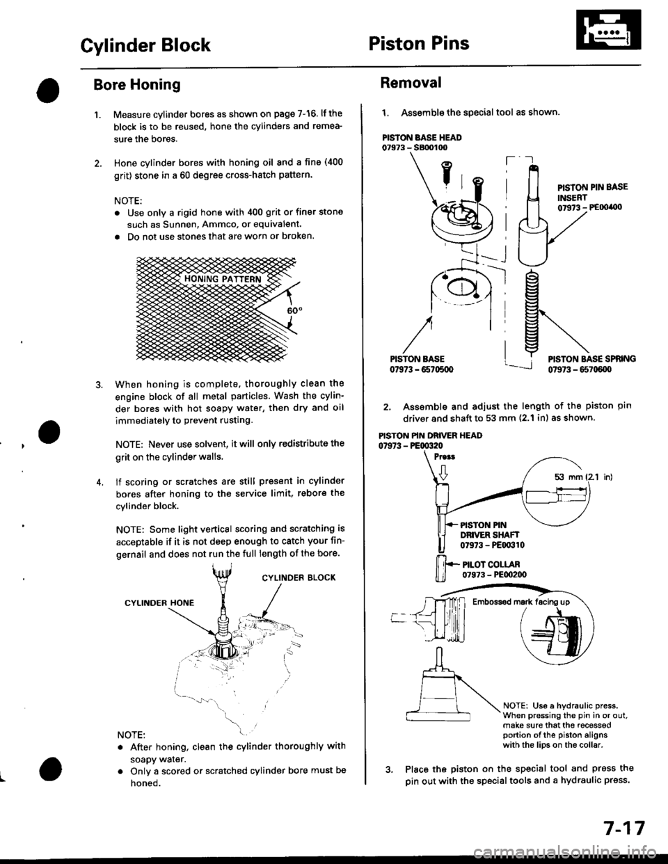
1.Measure cylinder bores as shown on page 7-16. lf the
block is to be reused, hone the cylinders and remea-
sure the bores.
Hone cylinder bores with honing oil 8nd a fine (400
grit) stone in a 60 degree cross-hatch pattern.
NOTE:
. Use only a rigid hone with 400 grit or finer stone
such as Sunnen, Ammco, or equivalent.
. Do not use stones lhat are worn or broken.
When honing is complete, thoroughly clean the
engine block of all metal particles. Wash the cylin-
der bores with hot soapY water, then dry and oil
immediately to prevent rusting.
NOTE: Never use solvent. it will only redistribute the
grit on the cylinder walls.
lf scoring or scratches are still present in cylinder
bores after honing to the service limit, rebore the
cylinder block.
NOTE: Some light vertical scoring and scratching is
acceptable if it is not deep enough to catch your fin-
gernail and does not run the full length of the bore.
CYLINOES BLOCK
CYLINDER
NOTE:
. After honing, clean the cylinder thoroughly with
soapy warer.
. Onlv a scored or scratched cylinder bore must be
noneo.
Removal
l. Assemble the special tool as shown.
PISTON BASE HEAD07973 - SBtx)too
ft
PISTON PIN BASE
INSERT01973 - PE00'0)
ptn
NOTEi Us6 a hydraulic press.When pressing the pin in or out.make sure that the recesssdportion of the piston alignswith the lips on the collar.
rg
g\
lj*N*,""
2. Assemble and adjust the length of the piston
driver and shaft to 53 mm (2.1 inl as shown.
PISTON PIN DRIVER HEAD07973 - PE00320
Proat
0
PISTON PINDRIVER SHAFT0t973 - PEqr310
PILOT COLLAR07973 - PE00200
3. Place the piston on the sp€cial tool and press the
pin out with the special tools and a hydraulic press.
Emboss6d mark facing up
7-17
Page 219 of 2189
Piston RingsCrankshaft Oil Seal
Alignment (cont'dl
TOP RING ---.>
SECOND RING >
MARK
,a-)
/\_4
o,.r^o( qffi<--sPACER
\Z-.
v
Rotate the rings in their grooves to make sure theydo not bind.
Position the ring end gaps as shown:
DO NOT position any ring gapat piston thrust surfaces.
DO NOT position any ring gapin line with the piston pin hole.OIL RING GAP
SECOND RING GAP
Approx.90
TOP RING GAP
7-22
Installation
The seal surface on the block should be dry.Apply a light coat of oil to the c.ankshaft and tothe lip of the seal.
1. Drive the crankshaft oil seal squarely into the right
side cover using the special tools.
HANDLE DRIVER07749 0010000
seal with thepan number sidefacing out.
Confirm that the clearance is equal all the way
around with a feeler gauge.
Clearance:0.5 - 0.8 mm (0.02 - 0.03 inl
NOTE: Refer to page 8-14 for installation of the oilpumo side crankshaft oil seal.
,(
\
Page 227 of 2189
Engine Lubrication
SpecialTools .......... "'.""".8'2
lllustrated Index ........... .'..' 8-3
Engine Oil
Inspection .....'......"....."'. 8-6
Replacement........'......".'.'..."...."......" 8-7
OilFilter
Rep1acement...............".'...'..'.....'.'...". 8-8
Oil Pressure
Testing '.....' 8-9
OilJet (B16A2 engine)
Inspection ...'.'......"...."'..8-10
OilPump
overhaul.'... .....'...'..'."""' 8-11
Removal/lnspection/lnstallation ..'.... 8-1 3