1996 HONDA CIVIC right side engine harness
[x] Cancel search: right side engine harnessPage 506 of 2189
I
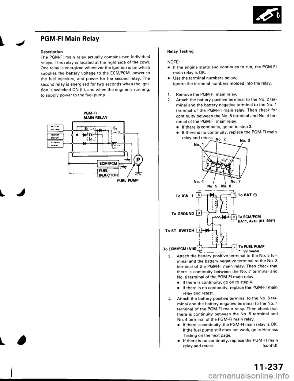
PGM-FlMain Relay
Description
The PGM-Fl main relav actuallv contains two individual
relays. This relay is located at the right side of the cowl.
One relay is energized whenever the ignition is on which
supplies the battery voltage to the ECM/PCM, power to
the luel iniectors, and power for the second relay. The
second relay is energized lor two seconds when the igni-
tion is switched ON (lll, and when the engine is running,
to supply power to the luel pump.
PGM-FIMAIN RELAY
J
I
t
FUEL PUMP
Relay Testing
NOTE:
. It the engine starts and continues lo run. the PGM Fl
main relay is OK.
. Use the terminal numbers below;
ignore the terminal numbers molded into the relay,
1. Remove the PGM Fl main relay.
2. Attach the battery positive terminal to the No. 2 ter-
minal and the battery negative terminal to the No 1
terminal of the PGM-Fl main relay. Then check for
continuity between the No.5 terminal and No 4ter-
minal of the PGM Fl main relay.
. lf there is continuity, go on to step 3.
. lf there is nocontinuity, replacethe PGM-Fl main
relay and retest.No. 3No. 1
To lGN. 1
To GROUND
To ST. SWITCH
To ECM/PCM {A161
To 8AT O
To ECM/PCM{(a11, A241, (81. B9l*l
To FUEL PUMP.r '99 model
3.Altach the batterv positive terminal to the No.5 ter-
minal and the battery negative terminal to the No. 3
terminal of the PGM-Fl main relay. Then check that
there is continuity between the No. 7 terminal and
No. 6 terminal of the PGM-Fl main relay.
. lf there is continuity, go on to step 4
. lf there is nocontinuity, replacethePGM-Fl main
relay and retest.
Attach the battery positive terminal to the No. 6 ter-
minal and the battery negative terminal to the No. 1
terminal of the PGM Fl main relay. Then check that
there is continuity between the No. 5 terminal and
No. 4 terminal of the PGM-Fi main relay.
. lf there is continuity, the PGM-Fl main relay is OK.
lf the fuel pump still does not work, go to Harness
Testing on the next page.
. lf there is no continuity, replace the PGM Fl main
4.
(cont'd)
11-237
relay and retest.
Page 546 of 2189

\
'99 - 00 models excepi Dl6Y5 engine with M/T:
The scan tool indicates Diagnostic Trouble Code (DTC) P0452: A low voltage problem in the Fuel Tank Pressure
sensor.
The fuel tank pressure sensor converts fuel tank absolute pressure into electrical signals and inputs the ECM/PCM
OUTPUTVOLTAGE(vlt.5
0.5-7 kP.(-g) mmHg,-2 in.Hgl
+7 kP.
150 mmHg,2 in.Hgl
PRESSURE
I
Wire side of lemale terminals
FUEL TANKPRESSURE SENSORSUB.HARNESS6P CONNECTOR (C574 (C568)rl
vcc2(YEL/BLUIsG2{GRN/BLK}
Wire side o{ temale terminals
The MIL has been .eported on.
DTC P0452 is stored
Check the vacuum lines:
Check the vacuum lines of the
fuel tank pressure sensor lor mis-
routing, leakage, breakage and
cloggrng.
Are the vacuum hnes OK?
Problem veritication:1. Do the ECM/PCM Reset Proce-
du re,2. Bemove the fuel fill caP.
3. Turn the ignition switch ON {ll)
4. Monitorthe FTP Sensor voltage
with the Honda PGM Tester' or
measure voltage between body
groLrnd and ECM/PCM connec_
tor terminalA29.
lntermitlent tailure, 3Ystem b OK
at this time. Check for Poor con'
nections or loose wire3 at C131
{located under right side of dash},
C401 {located above under'dash
tuse/relay box), C574 (C568)*
llocdted under access Panel),C792 (tuel rank Prcssure sensorl
and ECM/PCM.
ls there approx.2 5 V?
Check for an open in wire {VCC2
line):1. Turn the ignition switch OFF.
2. Reinstall the ltrel fill caP
3, Remove the access Panel from
the floor.4. Disconnect the fuel tank Pres'sure sensor sub-harness 6P
5. Turn the ignition switch ON (ll).
6. At the access Panel side, mea_
sure voltage between the fuel
tank Pressure sensor sub-nar-
ness 6P connector No 5termi
nal and No. 6 termlnal.
Repair open in tho wire between
th6 fu€l tank Prossuro sen3oa and
the ECM/PCM lc28).ls there approx 5 V?
ECM/PCM CONNECTOR A (32P)
PTANK {LT BLUI
I
ll
(To page '11-278)
(cont'd)
Page 1484 of 2189
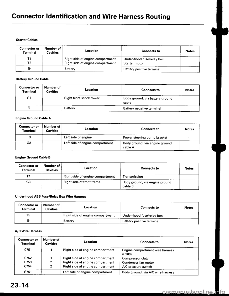
Connector ldentification and Wire Harness Routing
Connector or
Terminal
Number of
CavitiesLocalionConnec{s toNotes
T,I
r2
Right side of engine compartment
Right side of engine compartment
Under-hood fuse/relay box
Starter motor
BatteryBattery positive terminal
Starter Cables
A/C Wire Harness
Battery Ground Cable
Connector or
Terminal
Number of
CavitiesLocationConn€cts toNotos
Right front shock towerBody ground, via battery ground
caDte
oBafteryBattery negative terminal
Engine Ground Cable A
Conn€qtor or
Terminal
Number ot
CavitiosLocationConnects toNoles
T3Left side of enginePower steering pump bracket
G2Left side of engine compartmentBody ground, via engine ground
cable A
Engine Ground Cable B
Connector or
Terminal
Number of
CavitiesLocationConnecls toNoles
T4Right side of engine compartmentTransmission
Right side of front frameBody ground, via engine ground
cable B
Under-hood ABS Fusa/Relay Box Wire Harness
Connector or
Tgrminal
Number oI
CavitiesLocationConneqts toNotes
T5Right side of engine compartmentUnder-hood fuse/relay box
@BaneryBattery positive terminal
Connector or
Terminal
Number of
CavitiesLocationConnects toNotes
c753
c754
1
2
Right side of engine compartment
Right side of engine compartment
Right side of engine compartment
Right side of engine compartment
Engine compartment wire harness(c209)
Compressor clutch
Condenser fan motor
A,/C pressure switch
Left side of engine compartmentBody ground, via A,/C wire harness
23-14
Page 1486 of 2189

Connector ldentification and Wire Harness Routing
Engine Wire Harness lD16Y5, D16Y8 enginss): '96 - 98 models
Connector or
Torminal
Numbsr of
CavitissLocationConnects toNot€s
c 101c102c103c104c104c105c106c107c108c 109c110c111c112c113c114c115c116cl17c118c119c120cl21
c122c123cl23c124
c125
c127c12Ac129c130c131c132c 133c134c135
c136
c138c139c140c 141c142c 143c144cl44c145c'146cl47
10
1
22
14l4322l0I
2
2
2
2120
3l
14
14
1222
2
2
22
Left side of engine compartmentMiddle of engineMiddle of engineLeft side of engine companmentLeft side of engine compartmentMiddle of engineMiddle of engineMiddle of engineMiddle of engineMiddle of enginefvliddle of engineMiddle of engineMiddle of engineMiddle of engineMiddle of engineMiddle of engineMiddle of engineLeft side of engine compartmentMiddle of engineMiddle of engineMiddle of engineMiddle of engine
Middle of engineMiddle of engineMiddle of engineMiddle of engineMiddle of engineMiddle of engineMiddle of engineMiddle of engineMiddle of engineRight side of engine companmentBehind right kick panelUnder right side of dashUnder riOht side of dashUnder right side of dashUnder right side of dashUnder right side of dashUnder right side of dash
Under right side of dash
Under right side of dash
Middle of engineMiddle ot enginel iddle of engineMiddle of engineMiddle of ongineMiddle of engineLeft side of engine compartmentMiddle of engineMiddle of engineRight side of engine compartmentRight side of engine compartmentRight side of engine compartment
USACanada
Afi
USA
-' (A/r)
Main wire harness (C303)Crankshaft speed fluctuation (CKF) sensorEngine oil pressure switchAlternatorAlternatorNo. 'l fuel injectorNo. 2 fuel injectorNo.3 fuel injectorNo. 4 fuel injectorIAC valveThrottle position (TP) sensorl\4anifold absolute pressure (MAP) sensorIntake air temperature (lAT) sensorPower steering pressure {PSPI switchEVAP purge control solenoid valveJunction connectorJunction conn€ctorVehicle speed sensor {VSS}Countershaft speed sensorEngine coolant temp€rature (ECT) switch ADistributorEngine coolant temperature (ECT) sendingunrtEngine coolant temperature (ECT) sensorPrimary HO2S (sensor'l)Primary HO2S (sensor 1)Back-up light switchLock-up control solenoid valveSecondary HO2S (sensor 2)Mainshaft speed sensorLinear solgnoid valveShift control solsnoid valveStarter solenoidJunction connectorMain wire harnesE (C446)ECM/PCMPCMECMiPCMECM/PCMMain wire harness (C305)
Main wire harness (C305)
Main wire harness (C305)
Knock sensor (KS)IAC valveVTEC solenoid valveVTEC pressure switchEVAP control canister vent shut valveEGR control solenoid valveSecondary gear shaft speed sensorEGR valveEGR valveDrive pulley speed sensorSolenoid connector {CVT)Driven pulley speed sensor
*, (M/T)M/T*" INT\
*, tAtf)
NT:'96 model*,(A,/T):'97 - 98mooets
moqets
M/T
-1 (l,/T)*, (A,/T)-,(4,/T)*1 {M/T)*, (A,/T)*1 (CW)*, (A,T)
T101r102Left side of engine companmentRight side of engine companmentAlternatorUnder-hood fuse/relay boxG 101Middle of engineEngine ground, via engine wire harness
2
*1: Dl6Y5 engine*2: D16Y8 engine*3: D16Y5 (Ay'T), D16Y8 engines
3-16
Page 1488 of 2189
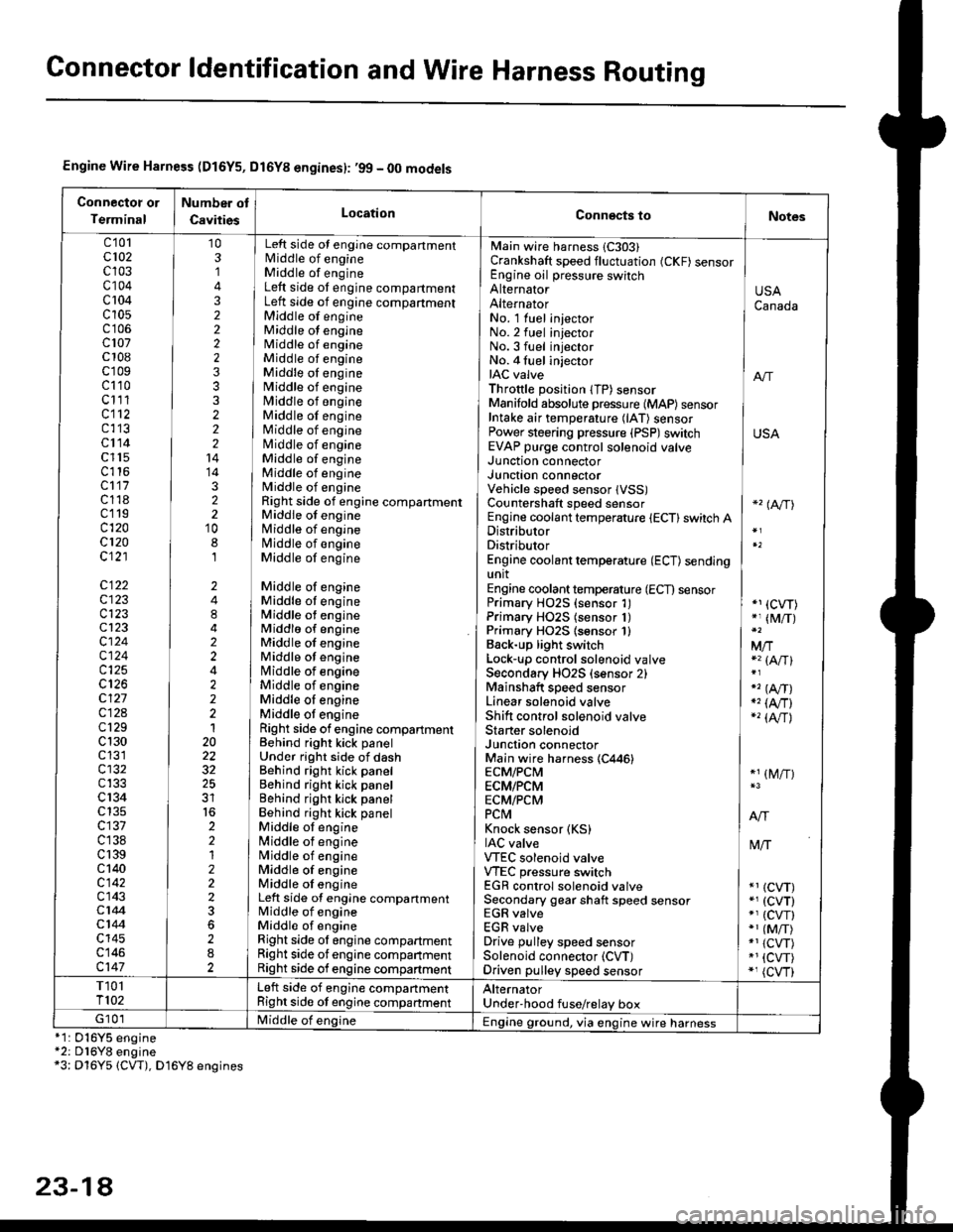
Gonnector ldentification and Wire Harness Routing
Engine Wire Harness (D16Y5, Dl6Yg engines): ,99 - 00 models
Connectot or
Terminal
Number ot
CavitiesLocationConn€cts toNotes
c'101cl02c103c104c 104c10s
c107c 108c'r09c110c111cl12c113cl14c l15c116cl17c118c119c120cl20c121
c122c123c123cl23cl24c124c125
c127c12Ac129c 130c131cl32c133c 134c135c137c138c 139c 140c142c143c144cl44c145c146c147
103,]
322223332221414322'10
8,l
2484224222120
32
2212223
282
No. 1 luel injector INo.2 fuel injectorNo.3 fuel injector ]No. 4 fuel injector iIAC valve I anThrottle position lTP) sensorManifold absolute pressure {MAP) sensor IIntake air temperature (lAT) sensor IPower steering pressure (PSP)switch USAEVAP purge control solenoid valve ]
Main wire harness 1C303)Crankshaft speed fluctuation (CKF) sensorEngine oil pressure switchAlternatorAlternator
Left side ot engine compartmentlvliddle of engineMiddle of engineLeft side ot engine compartmentLeft side of engine compartmentMiddle of engineMiddle ot engineMiddle of engineMiddle of engineMiddle oI engineMiddle of engineMiddle of engineMiddle of engineMiddle of engineNliddle of engineMiddle of engineMiddle of engineMiddle of engineRight side of engine compartmentMiddle of engineMiddle of engineN4iddle of engineMiddle of engine
Middle of engineMiddle ot engineMiddle ot engineMiddlo of engineMiddle of engineMiddle ot enginelrliddle of engineMiddle of engineMiddle oI engineMiddle ot engineRight side of engine compartmenlBehind right kick panelUnder right side of dashBehind right kick panelBehind right kick panelBehind righr kick panelBehind right kick panelMiddle ot engine[,liddle of engineN4iddle of engineMiddle of engineMiddle oI engineLeft side of engine compartmentMiddle of engineMiddle of engineRight side ol engine compartmentRight side of engine companmentRight side of engine compartment
USACanada
Junction connectorJUnct|On COnnectorVehicle speed sensor lVSS)Countershaft speed sensorEngine coolant temperature {ECT} switch ADistributorDistributorEngine coolant temperature (ECT) sendingunitEngine coolant temperature (ECT) sensorPrimary H02S (sensor 1)Primary HO2S (sensor 1)Primary HO2S lsensor 1)Back-up light switchLock'!p control solenoid valveSecondary HO2S (sensor 2)Mainshaft speed sensorLinear solenoid valveShift control solenoid valveStarter solenoidJunction connectorMain wire harness (C446)ECM/PCMECM/PCMECM/PCMPCtvtKnock sensor (KS)IAC valveVTEC solenoid valveVTEC pressure switchEGR control solenoid valveSecondary gear shaft speed sensorEGR valveEGR valveDrive pulley speed sensorSolenoid connector (CVT)Driven pulley speed sensor
*'� (A/TI
*1 (CVT)*, (M/T)
Mfia (A/Tl
" (A,/T)., (4,/r)-'� {AlrJ
*1 (M/T)
tvliT
*1 (CVT)*, (cvT)*' (cw)*1 (MiT)*1 {CVT)*1 {CVT)*, (cvr)
T101T102Left side of engine companmentRight side ot engine companmentAlternatorUnder'hood fuse/relay boxG 101Middle of englne IEngine ground, via engine wire harness*1: 016Y5*2: D16Y8*3: Dl6Y5
engineengine(CW), D16Y8 engines
23-14
Page 1490 of 2189
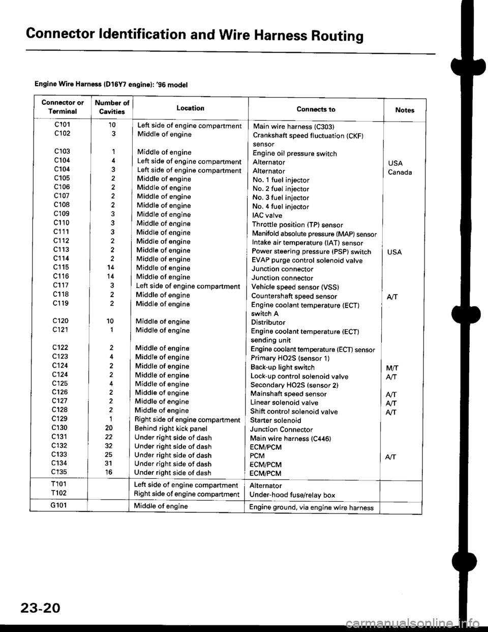
Gonnector ldentification and Wire Harness Routing
Engine Wire Harness {D16Y7 engine}: '96 model
Conneclor or
Terminal
Number ot
CavhiesLocationConnects toNotes
c101
c102
c 103
c104
c104
c105
c'r06
c107
c 108
c 109
c110
c111
c112
c l13
c't14
LttS
cl16
cl17
c118
cl19
c120
c121
c123
c124
c124
c125
c126
c't27
c12a
c129
c130
c131
c132
c133
c134
c135
10
1
4
5
'14
14
10
1
,,
2
2
1
22
31
16
No. 1 fuel injector INo. 2 fuel injector
No. 3 fuel injector INo,4 fuel injector
IAC valve l
Throttle position (TP)sensor IManifold absolute pressure (MAP) sensorIntake ai. temperature (lAT) sensor ]Power steering pressure (PSP) switch I USAEVAP purge control solenoid valve IJunction connector
Junction connector IVehicle speed sensor (VSS) |Countershaft speed sensor AlTEngine coolant temperature (ECT) I
Main wire harness (C303)
Crankshaft speed fluctuation (CKF)
sensor
Engine oil pressure switch
Alternator
Alternator
switch A
Distributor
Engine coolant temperature (ECT)
sending unit
Engine coolant temperature lECT) sensor
Primary H02S (sensor 1)
Back-up light switch
Lock-up control solenoid valve
Secondary HO2S (sensor 2)
Mainshaft speed sensor
Linear solenoid valve
Shift control solenoid valve
Staner solenoid
Junction Connector
Main wire harness {C446)ECM/PCM
PCM
ECM/PCM
ECM/PCM
Left side of engine compartment
Middle of engine
Middle of engine
Left side of engine compartment
Left side of engine compartment
Middle of engine
Middle of engine
Middle of engine
Middle of engine
Middle of engine
Middle of engine
Middle of engine
Middle of engine
Middle of engine
Middle of engine
Middle of engine
Middle of engine
Left side of engine compartment
Middle of engine
Middle of engine
Middle of engine
Middle of engine
Middle of engine
Middle of engine
Middle of engine
Middle of engine
Middle of engine
Middle of engine
Middle of engine
Middle of engine
Right side of engine compartment
Behind right kick panel
Under right side of dash
Under right side of dash
Under right side of dash
Under right side of dash
Under right side of dash
USA
Canada
M/T
AtJ
Afi
T101
T102
Left side of engine compartment
Right side of engine compartment
Alternator
Under-hood fuse/relay box
G101Middle of engineEngine ground, via engine wire harness
23-20
Page 1492 of 2189
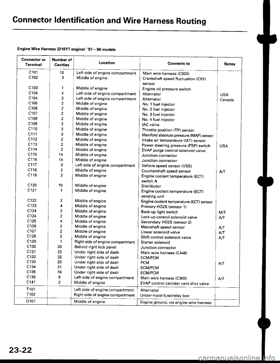
Connector ldentification and Wire Harness Routing
Engine Wire Harness {Dt6Y7 enginel: '97 - 9g models
Connectot or
Terminal
Number of
CsvitiesLocationConnects toNotes
c 101
c102
c103
c104
c104
c105
c106
c107
c 108
c109
cl10
clll
c112
cl13
cl14
c115
c1 l6
c117
c118
cl 19
cl20
c121
c122
c123
cl24
c124
c125
c126
c127
c128
c129
c 130
c 131
c132
c134
c135
cl41
10
1
2
10
I
2
2'>
4
t
20
3r
2
No. l fuel injector
No.2 fuel injector
No. 3 fuel injector INo. 4 fuel injector
IAC valve ]Throttle position (TP) sensor IManifold absolute pressure (MAP) sensorIntake air temperature (lAT) sensor ]Power steering pressure (PSp) switch I USAEVAP purge control solenoid valve
Junction connector IJunction connector IVehicle speed sensor (VSS)
Countershaft speed sensor I enEngine coolant temperature (ECTI
Main wire harness (C303)
Crankshaft speed fluctuation (CKF)
sensor
Engine oil pressure switch
Alte|'nator
Alternator
switch A
Distributor
Engine coolant temperature (ECT)
sending unit
Engine coolant temperature (ECT) sensor
Primary HO2S (sensor 1)
Back-up light switch
Lock-up control solenoid valve
Secondary H02S (sensor 2)
Mainshaft speed sensor
Linear solenoid valve
Shift control solenoid valve
Staner solenoid
Junction connector
Main wire harness (C446)
Left side of engine compartment
Middle of engine
Middle of engine
Left side of engine compartment
Left side of engine compartment
Middle of engine
Middle of engine
Middle of engine
Middle of engine
Middle of engine
Middle of engine
Middle of engine
Middle of engine
Middle of engine
Middle of engine
Middle of engine
Middle of engine
Left side of engine compartment
Middle of engine
Middle of engine
Middle of engine
Middle of engine
Middle of engine
Middle of engine
Middle of engine
Middle of engine
Middle of engine
Middle of engine
Middle of engine
Middle of engine
Right side of engine compartment
Behind right kick panel
Under right side of dash
Under right side of dash
Under right side of dash
Under right side of dash
Under right side of dash
Left side of engine compartment
Middle of engine
USA
Canada
Mtr
AIT
ECM/PCM
PcM I ArrECM/PCM
ECM/PCM
Main wire harness {C305) | AftEVAP control canister vent shut valve
T 101
r102
Left side of engine compartment
Right side of engine companment
Alternator
Under-hood fuse/relay box
G 101Middle of engineEngine ground, via engine wire harness
23-22
Page 1494 of 2189
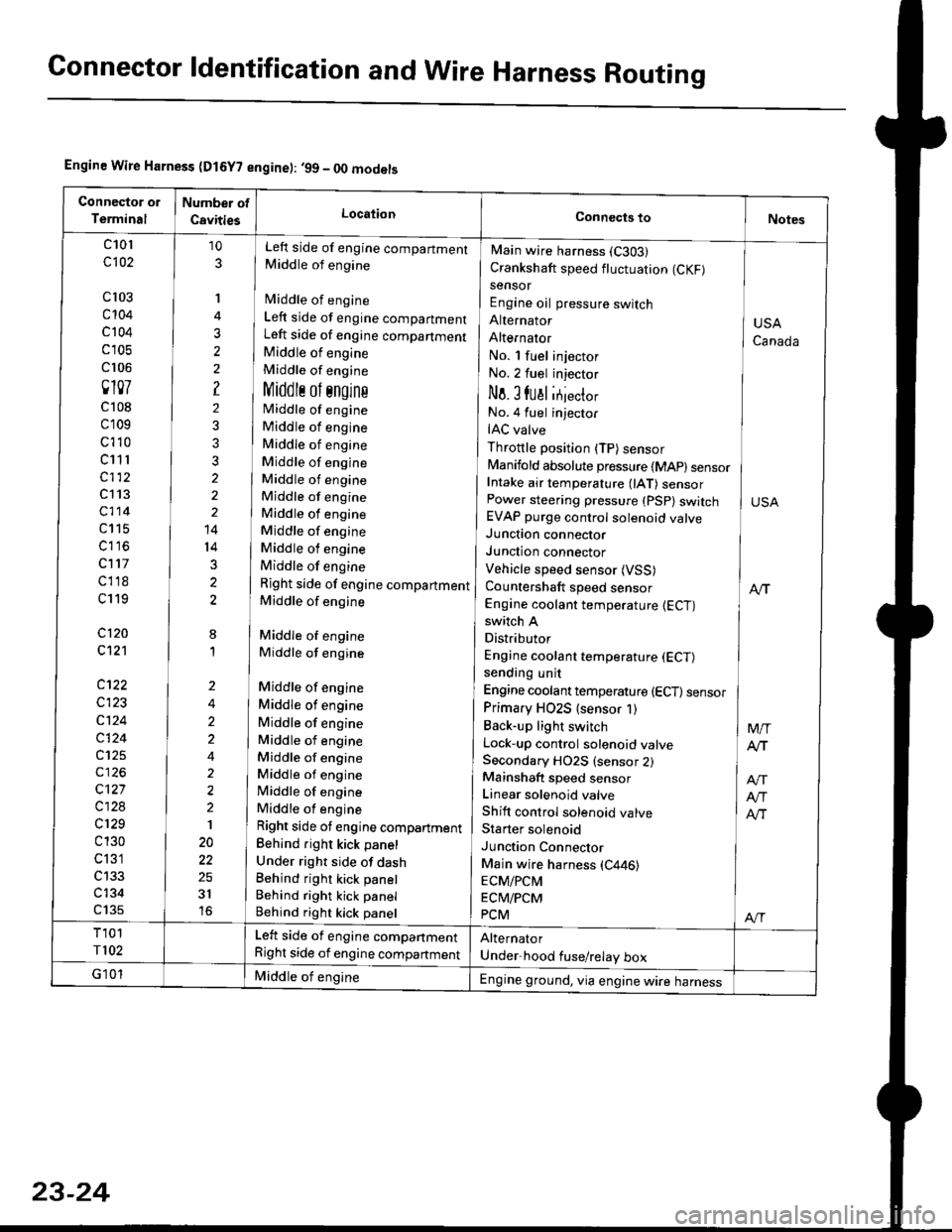
Connector ldentification and WireHarness Routing
Engine Wire Harness (D15Y? engine): ,99 - OO models
c101
c102
cl03
c't04
c 104
c 105
cr 06
0107
c108
c109
c't 10
c11 r
c112
c113
c114
c115
c116
c117
cl18
c119
c120
c121
c122
c123
c124
c124
c125
c127
c128
c129
c 130
c 131
c134
c135
10
3
'I
3
?
2
3?
2
14
14
3
2
8
1
Left side of engine compartment
Middle of engine
fvliddle of engine
Left side of engine compartment
Left side of engine companment
Middle of engine
Middle of engine
Middlr ol sngins
Middle of engine
Middle of engine
Middle of engine
Middle of engine
Middle of engine
Middle of engine
Middle of engine
Middle of engine
Middle of engine
Middle of engine
Right side of engine compartment
Middle of engine
Middle of engine
Middle of engine
Middle of engine
Middle of engine
Middle of engine
Middle of engine
Middle of engine
Middle of engine
Middle of engine
Middle of engine
Right side ot engine compartment
Behind right kick panel
Under right side of dashBehind right kick panel
Behind right kick panel
Behind right kick panel
Main wire harness (C303)
Crankshaft speed fluctuation (CKF)
sensor
Engine oil pressure switch
Alternator
AlternatOr
No. l fuel injector
No.2 fuel injector
No. I fual itjecto,
No.4 fuel injector
IAC valve
Throttle position (TP) sensor
Manifold absolute pressure {MAp) sensorIntake air temperature 0AT) sensorPower steering pressure (PSp) switchEVAP purge control solenoid valveJunction connector
Junction connector
Vehicle speed sensor (VSS)
Countershaft speed sensor
Engine coolant temperature {ECT)switch A
Distributor
Engine coolant temperature (ECT)
sending unit
Engine coolant temperature (ECT) sensor
Primary HO2S (sensor 1)
Back-up light switch
Lock-up control solenoid valveSecondary HO2S (sensor 2)Mainshaft speed sensor
Linear solenoid valve
Shift control solenoid valve
Starter solenoid
Junction Connector
Main wire harness (C446)
ECM/PCM
ECM/PCM
PCM
USA
Canada
M/T
Atr
Atr
Alr
Al-|.
Left side of engine compartment
Right side of engine compartment
Middle of engineEngine ground, via engine wire harness
23-24