Page 1242 of 2189

Doors
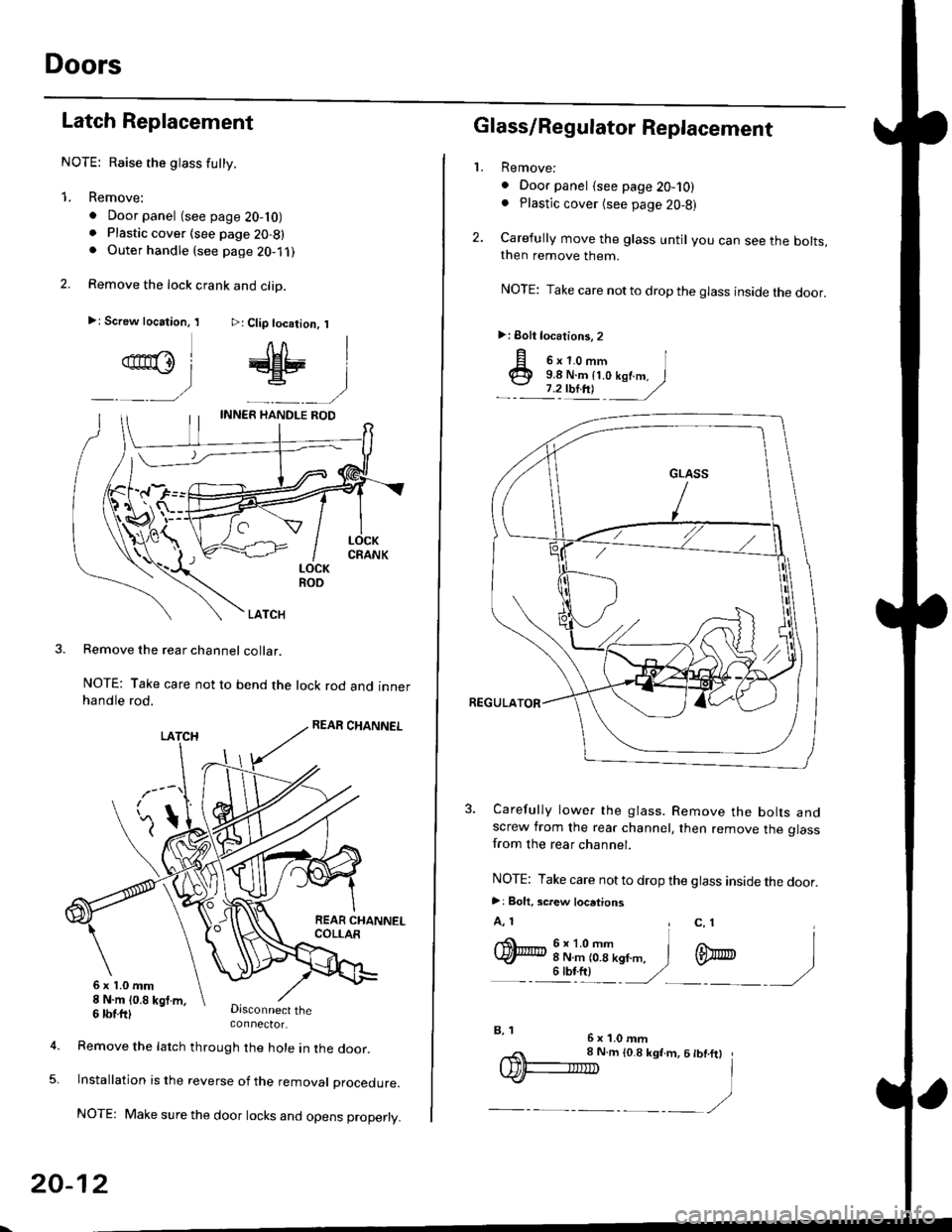
Latch Replacement
NOTE: Raise the glass futty.
1. Remove:
. Door panel (see page 20-10). Plastic cover (see page 20-8). Outer handle (see page 2O-1 ,l
2. Remove the lock crank and clip.
>: Screw location, I >: Clip location, I
qn@l # |
_ __) _-__)
LOCKROO
LATCH
Remove the rear channel collar.
NOTE: Take care not to bend the lock rod and innerhandle rod.
Disconnect theconnector.
6x1.0mm8 N.m (0.8 kgt m,
5.
6 tbtttl
Remove the latch through the hole in lne door.
lnstallation is the reverse of the removat proceoure.
NOTE: Make sure the door locks and opens properly.
20-12
,,< 8 N.m to.8 ksf.m, 6 tbt.ftt
IDF-IIID I
.)-__,/
2.
L
p o'r.o-,n I@ 9.8 N.m {t.o kof.m. I
.- :'zulnt -
/
3. Carefully lower the glass. Remove the bolts andscrew from the rear channel, then remove the glassfrom the rear channel.
NOTE: Take care not to drop the glass inside the door.
>: Bolt. screw locations
A, 1 , c, 1I
q)h:iT(--n,,". i m
- - illt) '/ -)
Glass/Regulator Replacement
Remove:
. Door panel {see page 20-10). Plastic cover (see page 20,8)
Carefully move the glass until you can see the bolts,then remove them.
NOTE: Take care notto drop the glass inside the door.
>: Eolt locations, 2
6x1.0mmB, 1
Page 1247 of 2189
bOuter Handle Replacement
NOTE: Raise the glass fully.
1. Remove:
. Door panel
. Plastic cover (see page 20-14)
2. Pull out the retainer clip.
3.e\
CYLINOER PROTECTOR
LOCK CYLINDER
RETAINERCLIP
Remove the bolts, then remove the cylinder protec-
tor, lock cylinder and outer handle.
>: Bolt locations,2
6x1.omm ]9.8 N.m {1.0 kgf.m,1.2tbl,ttl )_, _-_-,/
CYLINDERPROTECTOR
LOCK CYLINOER
CYLINOER ROD
20-17
4. Pull out the outer handle. Pry the outer handle rod
out of its joint using diagonal cutters.
NOTE:
. To ease reassembly, note location @ ot the outer
handle rod on the joint before disconnecting it.
. Take care not to bend the outer handle rod.
. Use a shop towel to protect the opening in the
door.
DIAGONALCUTTERS
SHOPTOWEL
5. Installation is the reverse of the removal procedure.
NOTE: Make sure the door locks and opens properly.
EUSHINGReplace.
\
,pr,
Page 1248 of 2189
Doors
Latch Replacement
NOTE: Raise the glass fully.
1. Remove:
. Door panel (see page 20-16)
. Plastic cover (see page 20-14). Outer handle {see page 20-17}
2. Remove the rod protector.
LATCH
PROTECTOR
20-18
3. Remove the bolts and move the center lower channel.
NOTE: Take care not to bend the inner handle rod
and lock rods.
>: Screw locations
A>,38>,3
q)
CENTER LOWEBCHANNEICBANKHOLDER
Disconnectthe connector,
6x1.0mm8 N.m 10.8 kgt.m,6 tbtft)
Remove the inner handle, then remove the latch
through the hole in the door.
lnstallation is the reverse of the removal procedure.
NOTE: Make sure the door locks and opens properly.
5.
6x1.0mm l
ffu 6 N.m {0.6 kef.m,
_" 11111 )
Page 1318 of 2189

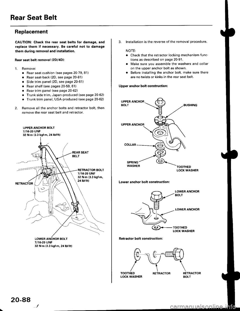
Rear Seat Belt
Replacement
CAUTION: Chack the rear seat belts for damage, and
replace them if necessary, 8e carolul not to damage
lhem during removal and installation.
Rear seat belt removal {2Dl4D}:
1. Remove:
. Rear seat cushion (see pages 20-79, 81)
. Rear seat-back (2D, see page 20-81)
. Side trim panel (2D, see page 20-61)
. Rear shelf (see pages 20-59,61)
. Rear trim panel {see page 20-62}
. Trunk side trim, Japan-produced (see page 20-62)
. Trunk trim panel, USA-produced (see page 20-62)
2. Remove all the anchor bolts and retractor bolt, then
remove the rear seat belt and retractor.
UPPER ANCHOR BOLT7/16-20 UNF32 N.m (3.3 kgf.m,2,1 lbtft)
RETNACTOR BOLT7/1F20 UNF32 N.m {3.3 kgf.m,24 tbt.ft)
7/16-20 UNF32 N.m {3.3 kgf.m,24lbt.ft)
20-88
R€TRACTOB
3. Installation is the reverse of the removal procedure.
NOTE:
. Check that the retractor locking mechanism func-
tions as described on page 20-91.
. lvlake sure you assemble the washers and collar
on the upper anchor bolt as shown.
. Before installing the anchor bolt. make sure there
are no twists or kinks in the rear seat belt.
Upper anchor boh condruqtion:
SPRINGWASHER
Lower anchor bolt construction:
LOWER ANCXOREOLT
LOWER ANCHOR
Retractor bolt construction:
RETRACTORBOLT
t7 /7--^,l/rn .----. A -nrfi|lH \
tr\7-\
/\TOOTHEDLOCK WASHER
Page 1718 of 2189

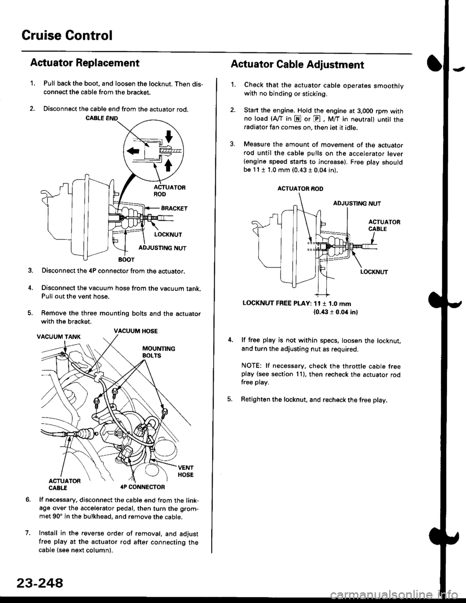
Cruise Control
t
D=
t
Astuator Replacement
1.Pull back the boot, and loosen the locknut. Then dis-
connect the cable from the bracket.
Disconnect the cable end from the actuator rod.
Disconnect the 4P connector from the actuator.
Disconnect the vacuum hosa from the vacuum tank.Pull out the vent hose.
Remove the three mounting bolts and the actuator
with the bracket.
CABTI aP CONNECTOR
lf necessary, disconnect the cable end from the link-age over the accelerator pedal, then turn the grom-
met 90' in the bulkhead, and remove the cable,
Install in the revers€ order of removal, and adjust
free play at the actuator rod after connecting thecable (see ne)d column).
7.
VACUUM HOSE
23-244
1.
Actuator Cable Adjustment
Check that the actuator cable operates smoothlywith no binding or sticking.
Stan the engine. Hold the engine at 3,000 rpm withno load (Afl'in N or E, M/T in neutral) untit theradiator fan comes on, then let it idle.
Measure the amount of movement of the actuato.rod until the cable pulls on the accelerator lever(engine speed starts to increase). Free Dlay shouldbe 11 t 1.0 mm (0.43 I 0.04 in).
LOCKNUT FREE PLAY: 11 1 1.0 mm
{o.i|:l r 0.oit in}
lf free play is not within specs, loosen the locknut,
and turn the adjusting nut as required.
NOTE: lf necessary. check the throttle cable freeplay (see section 11). then recheck the actuator rodfree play.
Retighten the locknut, and recheck the free play.
ACTUATOR ROD