1996 HONDA CIVIC Rod bolts
[x] Cancel search: Rod boltsPage 210 of 2189
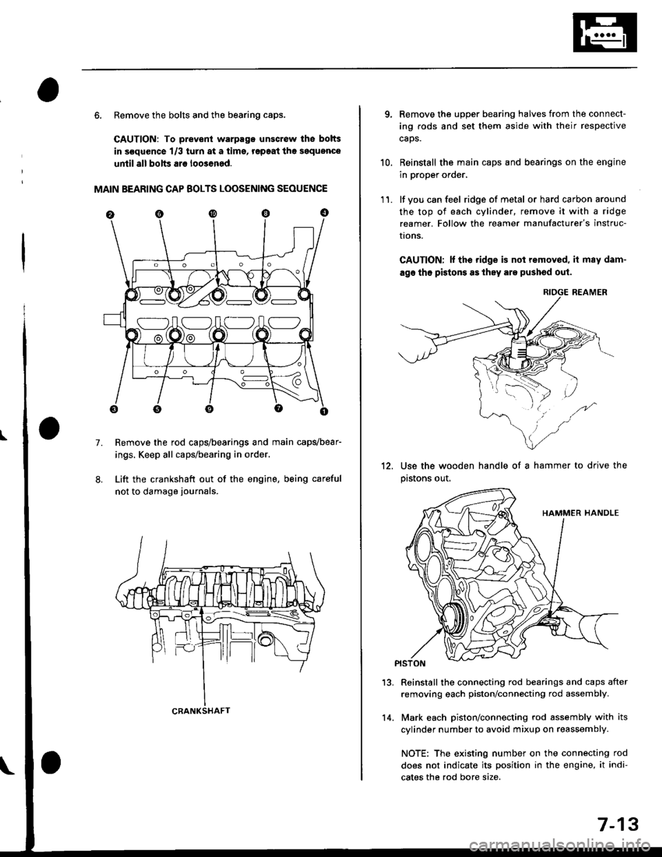
6. Remove the bolts and the bearing caps.
CAUTION: To prevenl warpago unscrow lhe bolts
in s€quence 1/3 turn at a tims, r€paat the soquence
until all bolts ar€ loo3ened.
MAIN BEARING CAP BOLTS LOOSENING SEOUENCE
Remove the rod caps/bearings and main capvbear-
ings. Keep all caps/bearing in order.
Lift the crankshaft out of the engine, being careful
not to damage journals.
7.
S:_]ILOJLOAO
CRANKSHAFT14.
7-13
qRemove the upper bearing halves from the connect-
ing rods and set them aside with their respective
caos.
Reinstall the main caps and bearings on the engine
in proper order,
lf you can feel ridge of metal or hard carbon around
the top of each cylinder, remove it with a ridge
reamer. Follow the reamer manufacturer's instruc-
I|ons.
CAUTION; lf the ridge is not removed, it may dam-
age tho pistons as they are pushod out.
RIOGE REAMER
10.
11.
12.Use the wooden handle of a hammer to drive the
pastons out.
13.Reinstall the connecting rod bearings and caps after
removing each piston/connecting rod assembly.
Mark each piston/connecting rod assembly with its
cylinder number to avoid mixup on reassembly.
NOTE: The existing number on the connecting rod
does not indicate its position in the engine, it indi-
cates the rod bore size.
Page 220 of 2189
PistonsGrankshaft
lnstallation
Before installing the pistons, apply a coat of
engine oil to the ring grooves and cylinder
bores.
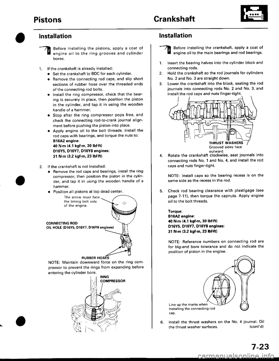
lf the crankshaft is already installed:
. Set the crankshaft to BDC for each cylinder.
. Remove the connecting rod caps, and slip short
sections of rubber hose over the threaded ends
of the connecting rod bolts.
. lnstall the ring compressor. check that the bear-
ing is securely in place, then position the piston
in the cylinder, and tap it in using the wooden
handle of a hammer.
o Stop after the ring compressor pops free, and
check the connecting rod-to-crank journal align-
ment before pushing the piston into place
. Apply engine oil to the bolt threads. Install the
rod caps with bearings, and torque the nuts to:
815A2 engine:
40 N.m {,1.1 kgf.m, 30 lbf'ft|
D16Y5, D16Y7, D16Y8 engines:
31 N.m (3.2 kgf'm,23 lbf'ft)
lf the crankshaft is not installed:
. Remove the rod caps and bearings, install the ring
compressor, then position the piston in the cylin-
der, and tap it in using the wooden handle of a
hammer.
. Position all Distons at top dead center.
1.
2.
The arrcw must facethe taming belt sideof the engine.
CONNECTING ROOOIL HOLE lD16Y5, D16Y7, D16YB ongines)
NOTE: Maintain downward force on the ring com-
pressor to prevent the rings from expanding before
entering the cylinder bore.
RUBBER
,lll
lnstallation
Before installing the crankshaft, apply a coat of
engine oil to the main bearings and rod bearings.
Insert the bearing halves into the cylinder block and
connecting rods.
Hold the crankshaft so the rod journals for cylinders
No.2 and No. 3 are straight down.
Lower the crankshaft into the block, seating the rod
journals into connecting rods No. 2 and No. 3, and
install the rod caps and nuts finger-tight.
1.
2.
3.
5.
Grooved sides faceoulward.Botate the crankshaft clockwise, seat journals into
connecting rods No, 1 and No.4, and install the rod
caps and nuts finger-tight.
NOTE: Install caps so the bearing recess is on the
same side as the recess in the rod.
Check rod bearing clearance with plastigage (see
page 7-11), then torque the capnuts. Apply engine
oil to the bolt threads.
Torque:
816A2 sngine:/l{, N.m {a.l kgf.m, 30 lbf'ftl
D16Y5, D16Y7, Dl6Y8 engines:
31 N.m (3.2 kgf.m, 23 lbf'ft|
NOTE: Reference numbers on connecting rod are
for big-end bore tolerance and do not indicate the
position of piston in the engine.
Line up the marks wheninstalling the connectrng rod
cap.
6. Install the thrust washers on the No. 4 journal. Oil(cont'd)
7-23
the thrust washer surfaces,
Page 221 of 2189
Crankshaft
Installation (cont'd)
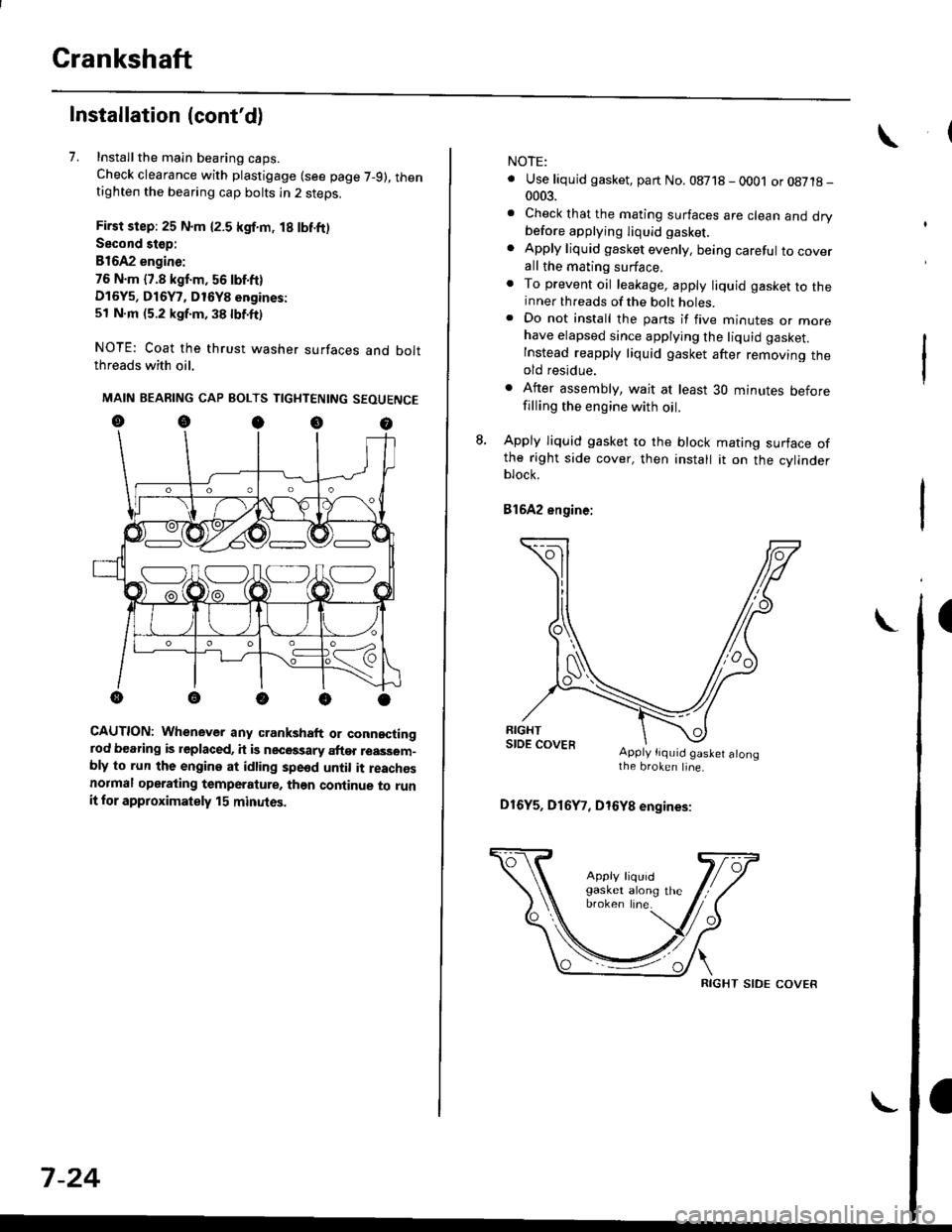
7. Installthe main bearing caps.
Check clearance with plastigage (see page 7-9), thentighten the bearing cap bolts in 2 steps.
First step: 25 N.m {2.5 kgf.m, 18 lbf.ft)
Second stop:
B1642 engine:
76 N.m {7.8 kgf.m, 56 lbf.ft)
D16Y5, D16Y7, D16Y8 engines:
51 N.m (5.2 kgf.m, 38 lbf.ft)
NOTE: Coat the thrust washer surfaces and boltthreads with oil.
MAIN BEARING CAP BOLTS TIGHTENING SEOUENCE
oocoo
CAUTION: Whenever any crankshaft or connectingrod bearing is replaced, it is necGssary after reassom-bly to run the engine at idling spe6d until it reachesnormal operating temperature, than continue to runit for approximately 15 minutos.
:V fr\-/.---\-/.-
7-24
NOTE:
. Use liquid gasket, part No. 08718 - 0001 or08718-0003.
. Check that the mating surfaces are clean and drybefore apptying liquid gasket.
. Apply liquid gasket evenly, being careful to coverall the mating surface.. To prevent oil leakage, apply liquid gasket to theinner threads of the bolt holes.. Do not install the parts if five minutes or morehave elapsed since applying the liquid gasket.
Instead reapply liquid gasket after removing theold residue.
. After assembly, wait at least 30 minutes beforefilling the engine with oil.
L Apply liquid gasket to the block mating surface ofthe right side cover, then install it on the cylinderblock.
Bl6A2 engine;
Apply tiquid gaslet alongthe broken line.
D16Y5, D16Y7, D16Y8 engines:
RIGHT SIDE COVER
Page 1087 of 2189
ISteering Linkage and Gearbox
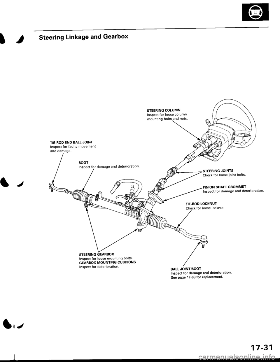
TIE-ROD END BALL JOINT
Inspect for faulty movement
and damage.
STEERING COLUMN
Inspect for loose column
mounting bolts and nuts
BOOTInspectdamage and deteriorataon
STEERING GEARBOXlnspect for loose mounting bolts.
GEARBOX MOUNTING CUSHIONS
Inspect f or deterioration
STEERING JOINTSCheck for loose joint bolts.
l./
TIE-ROD LOCKNUTfor loose locknut
BALL JOINT BOOT
Inspect for damage and deteriorataon'
See page 17-68lor replacement.
SHAFT GROMMETInspect for damage and deteriorataon.
lrz
17-31
Page 1129 of 2189
?
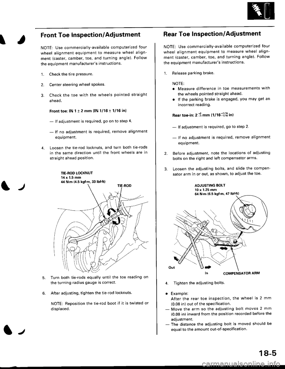
Front Toe Inspection/Adiustment
NOTE: Use commercially-available computerized four
wheel alignment equipment to measure wheel align-
ment (caster, camber, toe, and turning angle). Follow
the equipment manufacturer's instructions.
1. Check the tire pressure.
Center steering wheel spokes.
Check the toe with the wheels pointed straight
a head.
Front toe: lN 1 1 2 mm llN l/16 r 1/16 inl
- lf adjustment is required, go on to step 4.
- lf no adjustment is required, remove alignment
equrpmenr.
Loosen the tie-rod locknuts, and turn both tie-rods
in the same direction until the front wheels are in
straight ahead position.
TIE.ROD LOCKNUT'14 x 1.5 mm
4.
tJ
6.
Turn both tie-rods equally until the toe readang on
the turning radius gauge is correct.
After adjusting, tighten the tie-rod locknuts.
NOTE: Reposition the tie-rod boot if it is twisted or
displaced.
4,1 N.m {4.5 kgf.m, 33 lb{.ft)
2.
Rear Toe Inspection/Adiustment
NOTE: Use commercially-available computerjzed Iour
wheel alignment equjpment to measure wheel align-
ment (caster, camber, toe, and turning angle). Follow
the equipment manufacturer's instructions.
1. Release parking brake.
NOTE:
a Measure difference in toe measurements wlth
the wheels pointed straight ahead.
. if the parking brake is engaged, you may get an
incorrect readang,
Rear toe-in: 2 11 mm ttltollllS int
- lf adjustment is required, go to step 2.
- lf no adjustment is required, remove alignment
equipment.
Before adjustment, note the locations of adiusting
bolts on the right and left compensator arms
Loosen the adjusting bolts, and slide the compen
sator arm in or out. as shown, to adjust the toe
ADJUSTING BOLT10 x 1.25 mm
In CoMPENSAToR ARM
4. Tighten the adiusting bolts
. Example:
After the rear toe inspection, the wheel is 2 mm
(0.08 in) out of the specification.- Move the arm so the adjusfing bolt moves 2 mm
(0.08 in) inward trom the position recorded before the
adjustment.- The distance the adjusting bolt is moved should be
equal to the amount out-of-specification.
64 N.m 16.5 ksf m, 47 lbtft)
18-5
Page 1235 of 2189
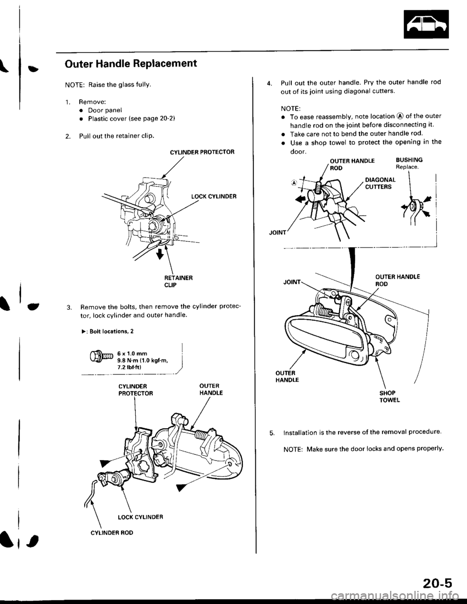
\:Outer Handle Replacement
NOTE: Raise the glass fully.
'1. Remove:
. Door panel
. Plastic cover (see page 2o-21
2. Pull out the retainer cliP.
6x1.omm Ii.e N.. tr.o rgf.-, I7.2 rbr.fi) ,2
C3.
CYLINDER PROTECTOR
LOCK CYLINDEB
RETAINERCLIP
Remove the bolts, then remove the cylinder protec-
tor, lock cylinder and outer handle.
>: Bolt locaiions,2
CYLINDER
LOCK CYLINDER
CYLINDER ROD
20-5
4. Pull out the outer handle. Pry the outer handle rod
out of its joint using diagonal cutters
NOTE:
a To ease reassembly, note location @ of the outer
handle rod on the joint before disconnecting it.
. Take care not to bend the outer handle rod.
o Use a shop towel to protect the opening in the
ooor.
OUTER HANDLEROD
DIAGONALCUTTERS
SHOPTOWEL
lnstallation is the reverse of the removal procedure
NOTE: Make sure the door locks and opens properly.
BUSHINGReplace.
\
,w.
5.
i4'
Page 1236 of 2189
Doors
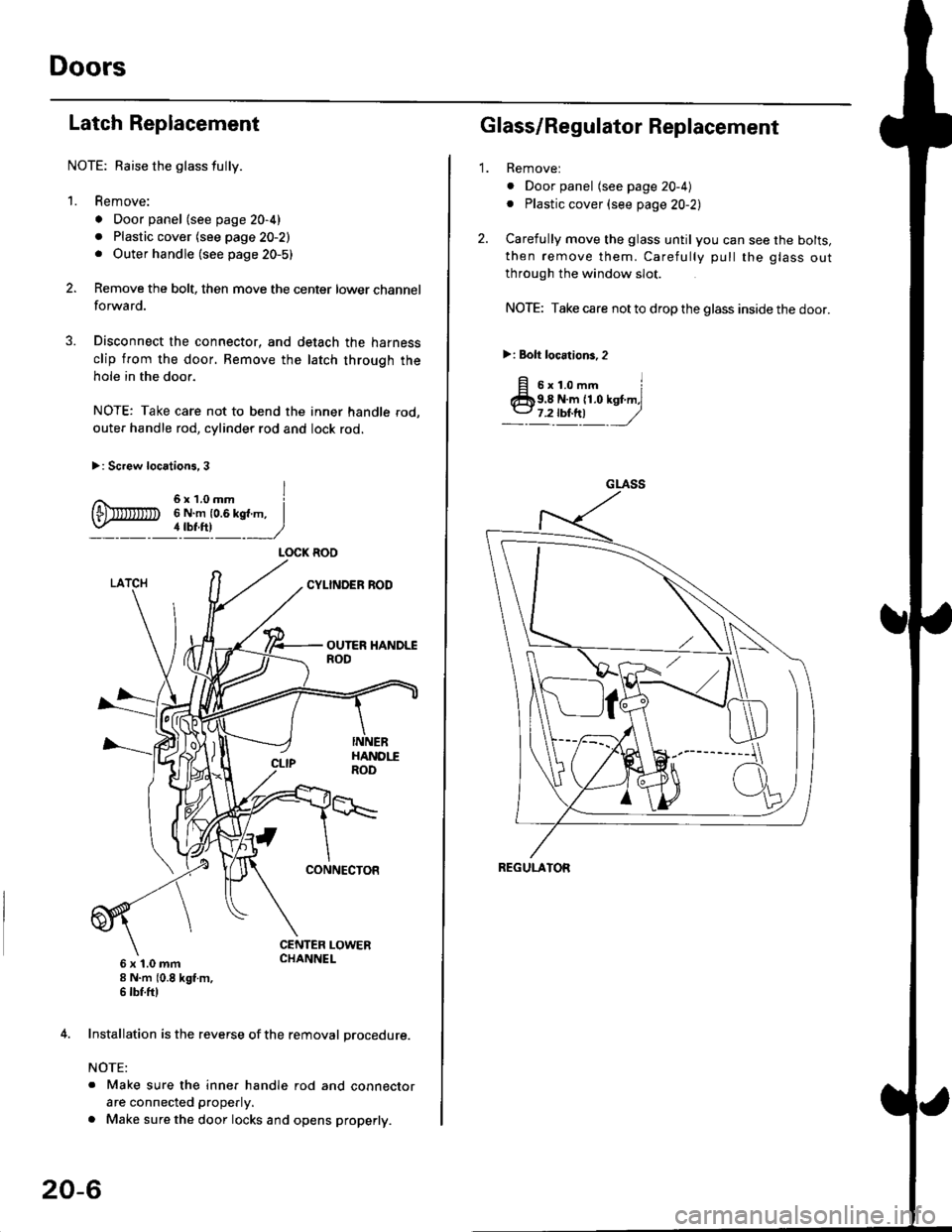
Latch Replacement
NOTE: Baise the glass fully.
1. Remove:
. Door panel (see page 20-4)
. Plastic cover (see page 20-2). Outer handle (see page 20-5)
Remove the bolt, then move the center lower channel
forwa rd.
Disconnect the connector, and detach the harness
clip from the door. Bemove the latch through the
hole in the door.
NOTE: Take care not to bend the inner handle rod,
outer handle rod, cylinder rod and lock rod.
>: Screw locations, 3
6 x 't.0 mm8 N.m (0.8 kgt m,6 tbf.ftl
4. Installation is the reverse of the removal procedure.
NOTE:
. Make sure the inner handle rod and connector
are connected properly.
. Make sure the door locks and opens properly.
LOCK ROO
20-6
'1.
Glass/Regulator Replacement
Removel
o Door panel (see page 20-4)
. Plastic cover (see page 20-2l,
Carefully move the glass until you can see the bolts,
then remove them. Carefully pull the glass out
through the window slot.
NOTE: Take care not to drop the glass inside the door.
>i Bolt loc.tions,2
fi s'r.o-. iClb9.8 N.m 11.0 kst m,l
_-l't!!t ,/
GLASS
REGULATOR
Page 1241 of 2189
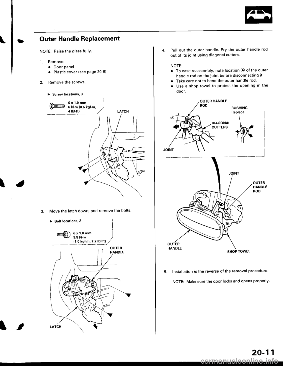
tOuter Handle Replacement
NOTE: Raise the glass fullY.
1. Remove:
. Door panel
. Plastic cover (see page 20-8)
2. Remove the screws.
>: Screw locations, 3
6x1.0mm6 N.m {0.6 kgf m,4 tbf.ftl
a\
3. Move the latch down, and remove the bolts.
>: Bolt locations,2
6x1.0mm9.8 N,m )11.O kst.n,7.2lbiftl //
4. Pull out the outer handle. Pry the outer handle rod
out of its joint using diagonal cutters.
NOTE:
. To ease reassembly, note location O of the outer
handle rod on the joint before disconnecting it.
. Take care not to bend the outer handle rod.
. Use a shop towel to protect the opening in the
door.
BUSHINGReplace.
OUTERHANDLEROD
5.
o
DIAGONAL \
:"'* ,w,
lnstallation is the reverse of the removal procedure
NOTE: N4ake sure the door locks and opens properly.
SHOP TOWEL
20-11