Page 252 of 2189
816A2 engino:
MUFFLER_.,. EXHAUST PIPE
-/- tlP
g
\6r1.omm
9.8 N m 11.0 kgf'm, 7.2 lbl'ttl
GASKETReplace.
8 x 1.25 mm2. N'm 12.2 kgl-m,t6 tbtf0Replace.Tighten the bolts insteps, alternatrngside-to-side.6x1,0mm9,8 N.m 11.07.2lbl4rl
SELF-LOCKING NUTl0 x 1.25 mm
3:t N.m {3.4 kgf m,24lbf'ftl
ReDlace.PRIMARY IIEATEDOXYGEN SENSOR{PRIMARY HO2S)ll N.m (4.5 kgl.m,33 tbt f0Replacement,
SECONDARY HEATEDOXYGEN SENSOR{SECONDARY HO2SIlrt N.m 14.5 kgf.m,33 rbl.ft)Replacement, page 9-13
GASKETR€place.
twcInspection, page 9-12GASKEISReplace.
SELF.L(rcKNG NUT10 x 1.25 mm5,r N.m 15.5 kgf.m, ,|{} lbf.ft)ReDlace.
8x1.25mm22 N.m {2.2 kgt m, 16 lbf.ftlReplsce.Tight6n the bolts in st6ps,alternating side-to-side.8 x 1.25 mm16 N.m 11.6 kgt.m,12 rbf.ft)F€pl8ce.
I
Replaca.
9-11
Page 253 of 2189
TWCHO2S
Inspection
l. Using a flashlight, make a visual check for plugging,
melting and cracking of the catalyst.
D16Y5, D16Y7 engines:
816A2, D16Y8 engines:
-\6{-)\
lT
a
A
FLASHLIGI{T
9-12
Replacement
Primary HO2S:
1. Remove the primary HO2S.
D16Y5, D15Y7 engines:
a. Disconnect the primary HO2S connector, thenremove the cover.
8 x'1.25 mm24 N.m {2.4 kgl.m,
PRIMARY H02SCONNECTOR
b. Remove the primary HO2S.
| \l ,l(
I bK/l
l llw.
/
(
PBIMARY HO2S44 N m (4.5 kgf.m, 33 tbI.ft)
Page 255 of 2189
HO2S
Replacement (cont'd)
b, Remove the secondarv HO2S.
02 SENSOR WRENCH
SECONOARY HO2S4,r N.m (4.5 kgf.m, 33 tbf.ft)
Install the secondary HO2S in reverse order ofremovat.
9-14
wa
Page 256 of 2189
Cooling
fllustrated Index ."..."... ""' 10-2
Radiator
Replacement .'....'...."..."
Engine Coolant Refilling and
Bleeding
Cap Testing
Testing
Thermostat
Replacement .............'....
Testing
10-6
10-7
10-9
10-9
10-10
10-10
Engine Goolant TemPerature
(ECT) Switch
Testing """ 10-11
Water PumP
fffustrated Index ......'... " 10-12
Inspection ' 10'14
Replacement ..'..'...."...'.'....'..'.....'.""" 10-14
!
Page 257 of 2189

lllustrated Index
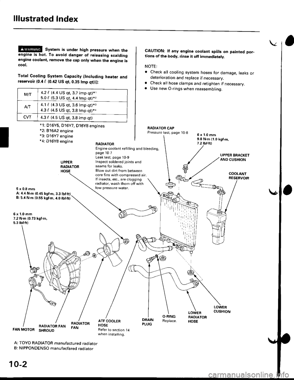
@@ system is under high pressure when theengine is hot. To avoid dangsr of rsleasing scaldingengine coolant, removo the cap only when the engine iscoot.
Total Cooling System Capacity flncluding heater andfoservoir (0.4 f (0.42 US qt, 0.35 tmp qt)ll:
*2: 81642 engine*3: D16Y7 engine*4: D16Y8 engine
CAUTION: lf any engine coolant spills on painted por-tions of the body, rinse it off immediately.
NOTE:
. Check all cooling system hoses for damage, leaks ordeterioration and replace if necessary.. Check all hose clamps and retighten if necessary.. Use new O-rings when reassembling.
RADIATOR CAPPressure test, page '10 86x1.0mm9.8 N.m {1.0 kgtm,7.2 tbt.ltl
UPPERRADIATORHOSE
UPPER BRACKETAND CUSHION
COOLANT
RAOIATOREngine coolant refilling and bleeding,page 10 7Leak test, page 10-9Inspect soldered joints andseams for leaks,Blow out dirt Irom betweencore fins with compressed air.lf insects, etc,, are cloggingradiator, wash them off withrow pressure water.
RESERVOIR
5x0.8mmA: ,1.4 N.m {0.45 kgf.m, 3.3 tbtftlg: 5.4 N.m (0.55 kgtm.4.0 tbf.ft)
6x1.0mm7.2 N.m (0.73 kgt.m,5.3 tbtftl
LOWERCUSHION
RADIATOR FANBADIATORFAN
DRAINPLUG
O-RINGReplace.
LOWEBRADIATORHOSE
FAN MOTOR SHROUD
Ar TOYO RADIATOR manufactured radiatorB: NIPPONDENSO manufacfared raoraror
10-2
Refer to section 14when installing.
Mt-|-4.2 f (4.4 US qt,3.7 tmp qt)*j
5.0 / (5.3 U$ q1, 4.4 16p q11*z
4.1 f (4.3 US qt, 3.6 lmp q0*3
4.31 (4.5 US qt, 3.8 tmp qt)*a
CVT4.3 f (4.5 US qt,3.8 Imp qt)
*1i D16Y5, D16Y7, D16Y8 engines
iil
Page 259 of 2189
lllustrated Index
(cont'd)
Engine Hose Connections:
D16Y5, D16Y8 engines:
Replace.
IAC VALVE(M/TI
IAC VALVE{A/T)
WATER BYPASSHOSE
THERMOSTATHOUSING
O.RINGReplace.
\
\
\
\h
CONNECTINGPIPE
HEATERVALVE
HEATERHOS€S
10-4
Page 260 of 2189
CONNECTINGPIPE
Engine Hose Conneqtions:
81642 engine:
O-RINGReplace.
b
WATER BYPASSHOSE
HEATERVALVE
HEATERHOSES
THERMOSTATHOUSING
ENGINE OIL COOLER
10-5
Page 261 of 2189
Radiator
Replacement
Drain the engine coolant.
Remove the upper and lower radiator hoses, andATF cooler hoses.
Disconnect the fan motor connector.
Remove the radiator upper bracket, then pull up theraotator,
RADIA
ATF COOLERHOSES (A/T)Refer to sectionwhen installing.
UPPER RAOIATOR HOSE
6x1.0mm7.2 N.m (0.73 kgf.m.5.3 tbf.ft)
1.
2.
3.
5. Remove the fan shroud assemblies and other partsfrom the radiator.
Install the radiator in the reverse order of removal:
NOTE:
. Set the upper and lower cushions securely.. Fill the radiator with engine coolant and bleedthe air.
6x1.0mmCAPY|lT,PS:|" i.i ru- ii b rgr.-,AND CUSHION7.2 tbr.ftl
14
(
I
RESEBVOIR TANK
RADIATOR
LOWER CUSHION
RAOIATOR FAN/SHROUDASSEMBLY
DRAIN PLUGO-RINGReplace.
LOWER RAOIATOR HOSE
ATF COOLERPIPES {A/T)
,iiiiii
10-6