Page 206 of 2189

Main Bearings
4.
Glearance
1.To check main bearing-to-journal oil clearance.
remove the main caps and bearing halves.
Clean each main journal and bearing half with a
clean shop towel.
Place one strip of plastigage across each main jour-
na l.
NOTE: lf the engine is still in the car when you bolt
the main cap down to check clearance, the weight
of the crankshaft and flvwheel will flaften the plasti-
gage further than just the torque on the cap bolt.
and give you an incorrect reading. For an accurate
reading, support the crank with a jack under the
counterweights and check only one bearing at a
time,
Reinstall the bearings and caps, then torque the
bolts.
lst step: 25 N'm (2.5 kgl'm. 18 lbf'ft)
FinalsteD:
B16A2 engine:
76 N.m (7.8 kgf.m, 56 lbf'ft)
D16Y5, Dl6Y7, D16Y8 engines:
51 N.m (5.2 kgf'm, 38 lbf'ft)
NOTE: Do not rotate the crankshaft during inspec-
tron.
Remove the cap and bearing again, and measure the
widest part ot the plastigage.
Main Boaring-toJournal Oil Clearance:
816A2 engine:
Standald {New}:
No. l, 2, 4, 5 Journals:
O.O2,l - 0.042 mm 10'00(B - 0.0017 in)
No. 3 Journals:
0.030 - 0.048 mm {0'0012 - 0'0019 in)
Servico Limit: 0.06 mm {0.002 in,
Dl6Y5, Dl6
r, Dl6Y8 engines:
Standard (Nsw):
No. 1,5 Journals:
0.018 - 0.035 mm {0.0007 - 0'001'[ in)
No. 2. 3, 4 Journals:
0.02,1 - 0.0,(2 mm {0'0009 - 0.0017 in}
Service Limit: 0.05 mm (0.002 in)
\
7-9
7.
lf the plastigage measures too wide or too narrow,
(remove the engine if it's still in the car), remove the
crankshaft, and remove the upper half of the bear-
ing. Install a new. complete bearing with the same
color code {select the color as shown on the next
page), and rechsck the clearance.
CAUTION: Do nol fil€, shim, or scrape the bearings
or tho cap3 to adiust cleatanc€.
lf the plastigage shows the clearance is still incor-
rect, try the next larger or smaller bearing (the color
listed above or below that one), and check again
NOTE: lf the proper clearance cannot be obtained
by using the appropriate larger or smaller bearings,
replace the crankshaft and start over.
Page 208 of 2189

Connecting Rod Bearings
Clearance
Remove the connecting rod cap and bearing half
Clean the crankshaft rod iournal and bearing half
with a clean shop towel.
Place plastigage across the rod journal.
Reinstall the bearing half and cap, and torque the nuts.
Torque
Bl6A2 engine:
40 N.m (4.1 kgl.m, 30 lbf'ft)
Dr6Y5, D16Y7, D16Y8 enginss:
31 N'm (3.2 kgf.m, 23 lbf ftl
NOTE| Do not rotate the crankshaft during inspection.
Remove the rod cap and bearing half and measure
the widest part of the plastigage.
Connecting Rod Bearing-to.Journal Oil Glearance:
816A2 engine:
Standard lNewl: 0.032 - 0.050 mm
10.0013 - 0.0020 in)
Service Limit: 0.06 mm 10.002 inl
D16Y5, D16Y7, D16Y8 engines:
Standard lNew): 0.020 - 0.038 mm
(0.0008 - 0.0015 in)
Service Limit 0.05 mm 10.002 inl
'1.
4.
lf the plastigage measures too wide or too narrow'
remove the upper half of the bearing, install a new,
complete bearing with the same color code (select
the color as shown in the right column), and
recheck the clearance.
CAUTION: Do not lile, shim, or scrape the bearings
or the caps to adiust clgarance.
lf the plastigage shows the clearance is still incorrect.
try the next larger or smaller bearing (the color listed
above or below that one), and check clearance again.
NOTE: lf the Droper clearance cannot be obtained
by using the appropriate larger or smaller bearings,
replace the crankshaft and start over.
PLASTIGAGE STRIP
\
7.
7-11
Selection
CAUTION: lf the codes are indecipherable because of
an accumulation of dirt and dust, do not sclub them
with a wile brush or scraper. Clean them only with sol-
vent or detergent,
Connecting Rod Code Location
Numbers have been stamped on the side of each con
necting rod as a code for the size of the big end Use
them, and the letters stamped on the crankshaft (codes
for rod journal size), to choose the correct bearlngs
Half of number ls
stamped on bearingcap and the otherhalf is stamped onrod.
Bearing ldentilication
Color code is on theedge ofthe bearing.
lfA--;T] |
lle"'tt l;llcorlll ll
I lD;;ilril |l-l
Larger brg end bore
Smaller Smallerrod bearlngjournal (thicker)
---------------- Smallerbearing{thrcker)
RedPinkGreen
PinkGreen
GreenErownBlack
GreenBrownBlackBlue
1234
Connecting Rod Journal Code Locations (Lettels)
Page 209 of 2189
Pistons and Crankshaft
Removal
1. Remove the oil pan assembly.
2. Remove the right side cover.
816A2 engine
D16Y5, Dl6Y7, D16Y8 ongines
RIGHT SIDE
7-12
\
3. Remove the oil screen.
4. R€move the oil pump.
816A2 engin€
OIL SCREEN
D16Y5, D1oyr, D16Y8 engin.s
O-RINGReplace.
5, Remove the baffle plate (816A2 engine).
OIL PUMP
Page 213 of 2189

Cylinder Block
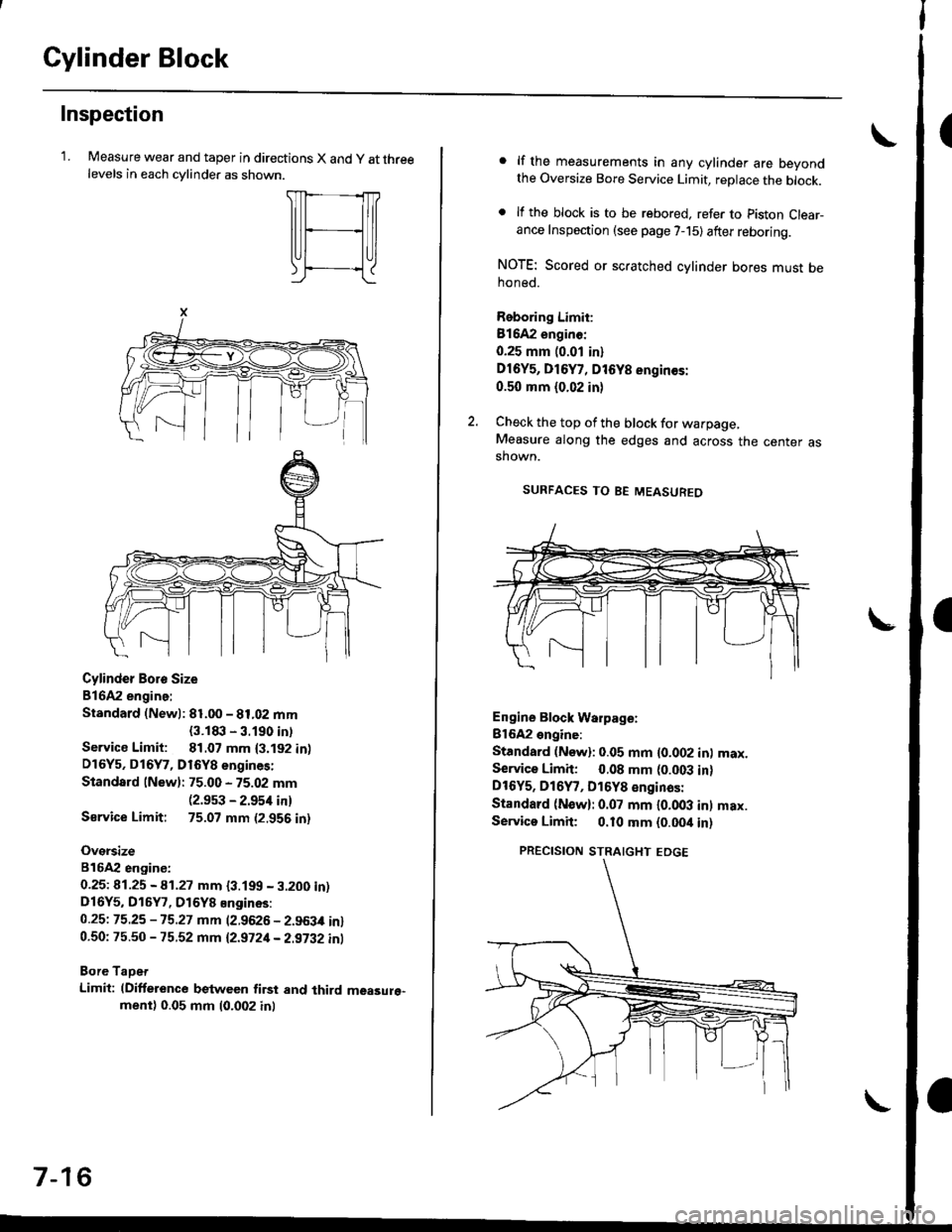
Inspection
'LMeasure wear and taper in directions X and y at threelevels in each cvlinder as shown.
Cylinder Boro Size
816A2 engine:
Standard (Newl: 81.00 - 81.02 mm
{3.1t|:l - 3.190 intService Limit: 81.07 mm {3.192 in)D16Y5, D16Y7, D16Y8 engines:
Standard lNew): 75.00 - 75.02 mm(2.9s3 - 2.954 in)
Sarvice Limit: 75.07 mm (2.956 in)
Oversize
816A2 engiDe:
0.25t 41.25 - A1.27 mm {3.199 - 3.200 in)D16Y5, D16Y7, D16Y8 Engines:
0.25t 75.25 -15.27 mm (2.9626 - 2.963,0 in)0.50: 75.50 - 75.52 mm 12.9721- 2.9i32 inl
Bore TaDet
Limit: (Difference between first and third measure"ment) 0.05 mm (0.002 inl
7-16
lf the measurements in any cylinder are beyondthe Oversize Bore Service Limit, replace the block.
lf the block is to be rebored. refer to piston Clear-ance Inspection (see page 7-15) after reboring.
NOTE: Scored or scratched cylinder bores must behoned.
Reboring Limit:
Bl642 enginc:
0.25 mm (0.01 in)
Dl6Y5, D16Y7, D16Y8 engin€s:
0.50 mm (0.02 in)
Check the top of the block for warpage,Measure along the edges and across the center asshown.
SURFACES TO BE MEASUREO
Engine Block Warpage:
Bl6A2 engine:
Standard (Now): 0.05 mm {0.002 inl max.Service Limh: 0.08 mm (0.003 in)DtOYs, D16Y7, D16Y8 €nginas:
Standard (N€w): 0.07 mm l0.OO3 inl max.Servica Limit; 0.10 mm {0.00it in)
PRECISION STRAIGHT EDGE
Page 216 of 2189

lnspection
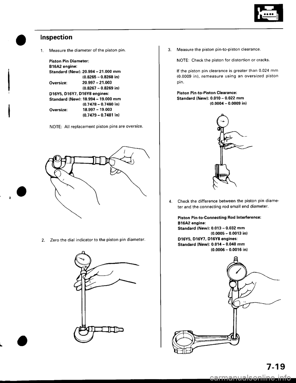
1.
Oversize:
Oversize:
NOTE; All replacement piston pins are overslze.
2. Zero the dial indicator to the piston pin diameter'
Measure the diameter of the piston pin.
Piston Pin Diametel:
B16A2 engine:
Standard {New): 20.994 - 21.000 mm
(0.8265 - 0.8268 in)
20.997 - 21.003
10.8267 - 0.8269 inl
D16Y5, Dl6Y7, Dl6YB engines:
Standard lNewl: 18.99,1- 19.000 mm
(0.7478 - 0.7480 inl
18.997 - 19.003
{0.7479 - 0.7481 in)
3. Measure the piston pin-to-piston clearance.
NOTE: Check the piston for distortion or cracks.
lf the piston pin clearance is greater than 0.024 mm
(0.0009 jn), remeasure using an oversized piston
pin.
Piston Pin-to-Piston Clearance:
Standard (New): 0.010 - 0.022 mm
(0.0004 - 0.0009 in)
Check the difference between the piston pin diame-
ter and the connecting rod small end diameter'
Piston Pin-to-Connesting Rod Interterence:
816A2 engine:
Standard (New): 0.013 - 0.032 mm(0.0005 - 0.0013 in)
D16Y5, D16Y7, Dl6YB engines:
Siandard lNewl; 0.014 - 0.040 mm
4.
10.0006 - 0.0016 inl
7-19
Page 217 of 2189

Piston Rings
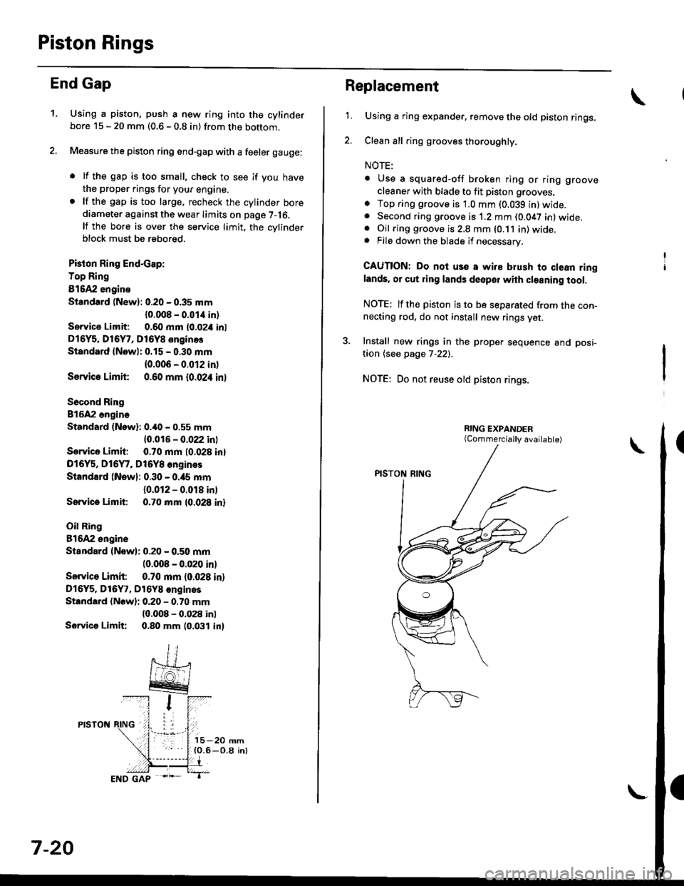
End Gap
1.Using a piston, push a new ring into the cylinderbore 15 - 20 mm (0.6 - 0.8 in) from the bottom.
Measure the piston ring end-gap with a feeler gauge:
. lf the gap is too small, check to see if you have
the proper rings for your engine.. lf the gap is too large. recheck the cylinder borediameter against the wear limits on page 7-16,
lf the bore is over the service limit, the cvlinderblock must be rebored.
Pkton Ring End-cap:
Top Ring
81642 engino
Siandtrd (New): 0.20 - 0.35 mm
{0.008 - 0.01,1 in)
Service Limit: 0.60 mm l0-02i1 inl
D16Y5. Dl6Y7, D16Y8 enginos
Standard lNewl: 0.15 - 0.30 mm
{0.006 - 0.012 in)
Ssrvic€ Limit 0.60 mm {0.024 inl
Socond Ring
816A2 ongina
Standard (Nowl: 0.40 - 0.55 mm
10.016 - 0.022 inl
Service Limit: 0.70 mm (0.028 inl
D16Y5, D16Y7, Dt6Y8 engines
Standard (New): 0.30 - 0.ia5 mm
{0.012 - 0.018 in)
Sorvice Limit 0.70 mm 10.028 inl
Oil Ring
81642 ongine
Standard {Now): 0.20 - 0.50 mm(0.008 - 0.020 inl
Sorvico Limit: 0.70 mm (0.028 in)
Dl6Y5. Dl6Y7, D16Y8 €nginos
Standard (Nowli 0.20 - 0.70 mm(0.008 - 0.028 inl
Servica Limit: 0.80 mm 10.031 in)
7-20
Replacement
1.Using a ring expander. remove the old piston rings.
Clean all ring grooves thoroughly.
NOTE:
. Use a squared-off broken ring or ring groove
cleaner with blade to fit piston grooves.
o Top ring groove is 1.0 mm (0.039 in)wide.. Second ring groove is 1.2 mm (0.047 in) wide.. Oil ring groove is 2,8 mm (0.11 in) wide.. File down the blade if necessary.
CAUTION: Do noi use a wire blush to clean ringlands. or cut ring lands deepol with cleaning tool.
NOTE: lfthe piston is to be separated from the con-necting rod, do not install new rings yet.
3. Install new rings in the proper sequence and posi-
taon (see page 7-22).
NOTE: Do not reuse old piston rings.
(Commercially available)
Page 221 of 2189

Crankshaft
Installation (cont'd)
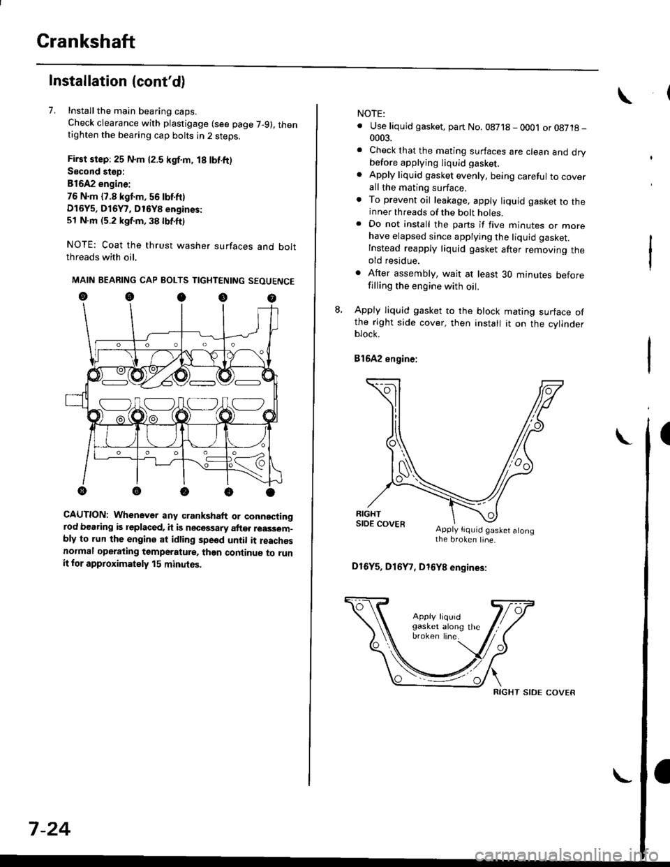
7. Installthe main bearing caps.
Check clearance with plastigage (see page 7-9), thentighten the bearing cap bolts in 2 steps.
First step: 25 N.m {2.5 kgf.m, 18 lbf.ft)
Second stop:
B1642 engine:
76 N.m {7.8 kgf.m, 56 lbf.ft)
D16Y5, D16Y7, D16Y8 engines:
51 N.m (5.2 kgf.m, 38 lbf.ft)
NOTE: Coat the thrust washer surfaces and boltthreads with oil.
MAIN BEARING CAP BOLTS TIGHTENING SEOUENCE
oocoo
CAUTION: Whenever any crankshaft or connectingrod bearing is replaced, it is necGssary after reassom-bly to run the engine at idling spe6d until it reachesnormal operating temperature, than continue to runit for approximately 15 minutos.
:V fr\-/.---\-/.-
7-24
NOTE:
. Use liquid gasket, part No. 08718 - 0001 or08718-0003.
. Check that the mating surfaces are clean and drybefore apptying liquid gasket.
. Apply liquid gasket evenly, being careful to coverall the mating surface.. To prevent oil leakage, apply liquid gasket to theinner threads of the bolt holes.. Do not install the parts if five minutes or morehave elapsed since applying the liquid gasket.
Instead reapply liquid gasket after removing theold residue.
. After assembly, wait at least 30 minutes beforefilling the engine with oil.
L Apply liquid gasket to the block mating surface ofthe right side cover, then install it on the cylinderblock.
Bl6A2 engine;
Apply tiquid gaslet alongthe broken line.
D16Y5, D16Y7, D16Y8 engines:
RIGHT SIDE COVER
Page 223 of 2189
CrankshaftOil Pan
Installation (cont'd)
NOTE:
. Apply a light coat of oil to the crankshaft and iothe lip of seal.. Use new O-rings and apply oil when installingthem.
10. lnstallthe oil screen.
816A2 engine:
6 x 1.O mml l N'm (1 .1 kgl.m,8 tbt.Irl
,.//
{ / cor*rt(..ao Replace.
t(^^
11 N.m 11 .1 kgf.m,a lbl'ltl ,/.rB tbt4tl /
*P/
& ^/t
O.RINGReplace.
OtL PutitP
D16Y5, D16Y7, D16Y8 engines:
24 N.m (2.4 kgf.m,'17 lbl.fr)
kgf.m,
OIL SCREEN
6 x 1.0 mm1 1 N.m {1 .1 kgf.m,
6x1.0mm11 N.m {1.18 tbt.rr)
I
Ia lbf.fr)
DOWEL PIN
rT
lle/ OIL PUMP6 x 1.0 mm11 N.ml l.1 kgf'm, a lbf.frl
7-26
Installation
D16Y5, Dl6Yg engines:
1. Install the oil pan gasket on the oil pan.
OIL PANGASKETReplace.
OIL PAN
I