Page 1448 of 2189

A/C System Service
Performance Test
The performance test will help determine if the air con-
ditioner system is operating within specifications.
Use only service equipment that is U.L.-listed and is cer-
tified to meet the reouirements of SAE J2210 to remove
HFC-134a (R-134a) from the air conditioner system.
CAUTION: Exposure to air conditionor rofrigerant and
lubricant vapor or mist can irrilalo €yes, nose and
throat. Avoid breathing tho air conditioner rstrigerrnt
and lubricant vapor or mist,
lf accidental system discharge occurs, ventilate work
area before resuming service.
R-134a service equipment or vehicle air conditioner sys-
tems should not be pressure tested or leak tested with
compressed air.
@ some mixtur$ of air and R-134a have been
shown lo b9 combustible rt glgvatad pr€ssur63 and can
resull in tire 01 oxplosion causing inlury ot property
damage. Never uao compre33ed air to pressure t99t R-
134a ssrvico 6quipmsnt or vohicla air conditioner sys-
tems.
Additional health and safety information may be obtained
from the refrigerant and lubricant manufacturers.
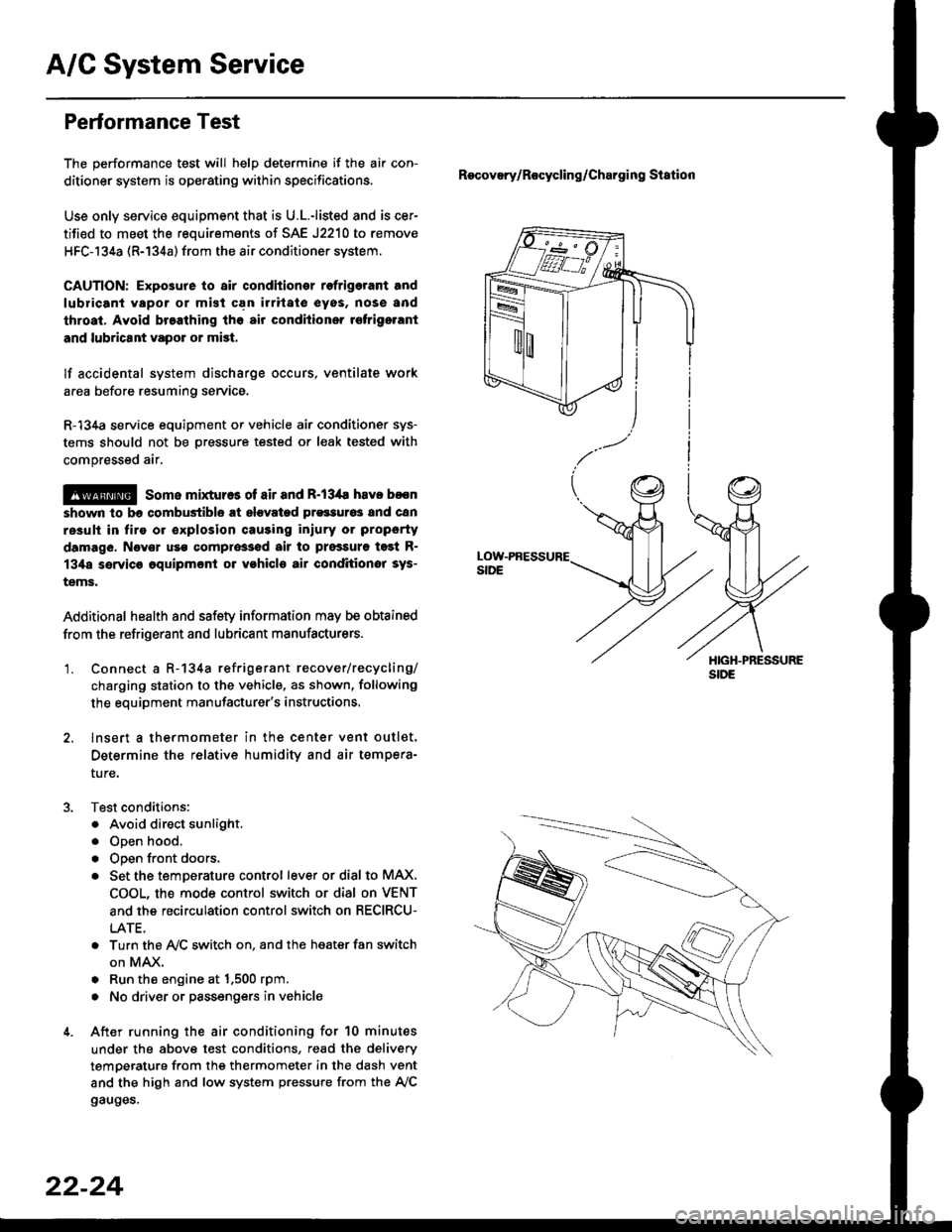
'1. Connect a R-134a refrigerant recover/recycling/
charging station to the vehicle, as shown, following
the equipment manufacturer's instructions.
2. lnsert a thermometer in the center vent outlet.
Determine the relative humidity and air tempera-
ture,
Test conditions:
. Avoid direct sunlight.
. Open hood.
. Open front doors.
. Set the temDerature control lever or dial to MAX,
COOL, the mode control switch or dial on VENT
and the recirculation control switch on RECIRCU-
LATE.
. Turn the A,/C switch on. and the heater fan switch
on MAX.
. Run the engine at 1,500 rpm.
. No driver or passengers in vehicle
After running the air conditioning for 10 minutes
under the above test conditions, read the delivery
temperature from the thermometer in the dash vent
and the high and low system pressure from the A,/C
gauges.
Recovery/Rocycling/Charging Station
22-24
Page 1953 of 2189

- How the Circuit Works
'96198 Models
The air delivery system directs the flow of air used
by the heater and air conditioner systems.
Mode Selection
Mode selection is controlled by the mode switches
in the heater control panel and the mode control
motor. When you select a specific mode, voltage is
applied through the dimming circuit to the LED,
which comes on, indicating the mode selected.
Ground is orovided to the mode control motor
though that mode switch. The motor then runs until
the air control door reaches the proper position.
Fresh/Recirculation 56lection
When you press the fresh or recirculation button, a
ground signal is sent from the heater control panel
to the recirculation control motor. The motor then
runs until the recirculation door reaches the proper
position. Battery voltage is also applied through the
dimming circuit to the corresponding LED, and the
LED comes on.
Refer to the Service Manual (Section 21, Heater) for
specitic tests or troubleshooting proc€dures.
'99J00 Models
The heater control panel receives battery voltage at
all times through fuse 47. With the ignition switch in
ON (ll), voltage is supplied to the heater control
panel through fuse 17. The control panel is
grounded at G402.
The heater control panel controls the air delivery
motors, and supplies a 5 VDC reterence voltage to
the air mixture control motor.
The air mixture and mode control motors each
receive inputs trom the heater control panel. The air
mix motor regulates the mixture of cold and hot air
by varying the position of the heater-evaporator doot
The mode control motor controls the direction and
volume of outlet air. The air flow can be directed to
the dashboard vents or the corner vents.
Both the air mixture control molor and mode control
motor are grounded by the h€aler control panel.
The recirculation control motor receives battery
voltage through fuso 17 when the ignition swilch is
in ON (ll). lt regulates the position of the fresh/recirc
door, and is controlled by two position inputs from
the heater control panel ("Recirc" and "Fresh").
Refer to the Service Manual (Section 21, Heater) tor
specific tests or troubleshooting procedures.
61-3
Page 1957 of 2189

- How the Circuit Works
Battery voltage is supplied through tuse 56 to the
A,/C compressor clutch r€lay contacts at all times.
With the ignition switch in ON (ll), vollage is applied
to the coil of the A,/C compressor clutch relay
through fuse 17. When you push the A,/C switch
ON, and the heater fan switch is in position | , 2, 3,
or 4, a "ground" input is provided to the engine
control module (ECM) or powertrain control module
(PCM) through the l'lC thermostat and the l'lC
pressure switch.
The A,/C compressor clutch relay is grounded by the
engine control module (ECM) or powertrain control
module (PCM). When energized, the A'lC
compressor clutch relay allows battery voltage to
turn on the A,/C comDressor clutch.
The A,/C ON indicator light comes on when the A,/C
system is requested.
A,/C Thermostat
The A'lC thermostat is located on the evaoorator
housing. The A,/C thermostat turns off the A,/C
compressor clutch if the temperature at the
evaporator goes below 3'C (37'F). This prevents
condensation from freezing on the evaporator fins
and blocking the air delivery into the passenger
compartment. The blower motor will keep running
when the sensor turns off the comDressor.
A,/C Pressure Switch
The fuC oressure switch is located in the condenser
outlet line where refrigerant is in a high
temperature/high pressure liquid state. The switch
will sense abnormally high or low pressure, and
open the circuit. This removes ground, and the
compressor will stop running.
Thermal Protectot
The thermal protector, located on the A,/C
compressor, opens and turns the compressor off if it
senses high temperature. Once the compressor
cools, the switch will close and the compressor will
begin running again.
Refer to the Service Manual (Section 22,
Air Conditioning) for specific tests or
troubleshooting procedures.
62-3