Page 1374 of 2189
Heater and Air Conditioning
Heater '.'..""" 21'1
Air Conditioning ......."'.. "' 22-1
SUPPLEMENTAL RESTRAINT SYSTEM (SRS}
The civic sRs includes a driver's airbag located in the steering wheel hub ln addition, all models (except some
models for canada) have a passenger's airbag located in the dashboard above the glove box'
Information necessary to safely service the sRS is included in this service Manual ltems marked with an asterisk (*)
on the contents page include, or are located near, sRs components. servicing, disassembling or replacing these
items will require special precautions and tools, and should therefore be done by an authorized Honda dealer'
@-";;il rendsring the SRS inoperative, which could lead to personal iniury or deaih in the svent of a sev€re
frontal collision. all SRS service work must be pertormed by an authorized Honda d€aler'
. lmploper service procedures, including incorrest removal and instsllation of the sRs, could lead to personal
iniury caused by unintentional deployment of the airbags'
o Do not bump the SRS unit. Otherwise. the system may fait in case of a collision. or the airbags may deploy
when the ignition switch is ON {ll}'
. sRs electrical wiring harncsses are id€ntified by yellow colol coding. Related components ale located in lhe
steering column, front console, dashboard, dashboald lowet panel, and in the dashboard above the glove box'
Do not use electricaltest equipment on these circuits.
Page 1425 of 2189
Air Conditioning
Speciaf Tools ......'.....' 22-2
f f f ustrated f ndex ......................... ".......' 22-3
Wiring/Connector Locations'.........'.... 22'4
Description
Outfine ............ .......22-s
Circuit Diagram
'96 - 98 Models ......"..........".......'.... 22-6
'99 Modef """""""' 22-7
Troubleshooting
Symptom Chart ".'......""................. 22-8
Flowcharts
Condenser Fan .........".................,..'. 22-9
Compressor .....""" 22-12
A/C System .........'.22'17
A/C Thermostat
Test ........'.......' """'22'21
Relays
Test ....."'......... ..""'22-21
A/C Service Tips and Precautions ......22-22
A/C System Torque Specifications '...22-23
A/C System Service
Performance Test ... '."......... ".... ....'..22-24
Pressure Test Chart .................. .... "' 22-26
Recovery ...".........," 22-27
Evaporator
Replacement .....",' 22'24
Overhauf .....-.....""' 22'29
Compressor {SANDEN}
Repf acement ......'.' 22-30
fffustrated fndex ......"..................'.... 22'32
Cf utch Inspection ......... "............ ...... 22-33
Clutch Overhau I ........................ ....... 22-34
Thermal Protector Replacement .... 22-36
Relief Valve Replacement ......'..."". 22-36
Compressor (DENSO)
Repfacement ..""',' 22-37
lf lustrated Index ............................... 22-39
Clutch lnspection ............."'...... "'.... 22-40
Cf utch Overhaul .....................'......... 22-41
Ref ief Valve Replacement'..'......"'.. 22-42
A/C Compressor Belt
Adiustment ............22'43
Condenser
Repfacement .......,,22'44
A/C System Service
Evacuation ...,,,.......22-45
Charging '..........--'..22'46
Leak rest """""""'22-46
Page 1426 of 2189
Special Tools
Bef. No. Tool NumberDescriptionQty I Page Reference
o
@
*07JGG - 00l0l0A
07sAz - 0010004
07947 - 6340300
07965 - 6920500
Belt Tension Gauge
Backprobe Set
Driver Attachment
Hub Assembly Gulde Attachment
1
'1
1
22-43
22-14,16
22-34
22-35' Included in the Belt Tension cauge Set, 07TGG-0010004.
a6r
L
3r
22-2
Page 1472 of 2189
Special Tools
Ref. No. Tool NumberDescriptionOty Page Reference
O)
@-
o
@
o
tol
A973X_041 _XXXXX
07JGG 00l0l0A
OTLAJ - PT3O2OA
07NAC - SR20100
07PM - 0010r 00
07MAJ - SP00300
Vacuum Pump Gauge, 0 - 30 in.Hg.
Belt Tension Gauge
Test Harness
Fuel Sender Wrench
SCS Service Connector
Keyless Entry Checker
1
1'I
1
1
1
23-245
23-140,141
23-142
23-105
23-264
': Included in Belt Tension Gauge Set 07T66 - 0010004
or/4,
(!
23-2
Page 1475 of 2189
t
Five-step Troubleshooting
2.
1.Verify The Complaint
Turn on all the components in the problem circuit to
verify the customer complaint. Note the symptoms.
Do not begin disassembly or testing until you have
narrowed down the problem area.
Analyze The Schematic
Look up the schematic for the problem circuit.
Determine how the circuit is supposed to work by
tracing the current paths from the power feed
through the circuit components to ground. lf several
circuits fail at the same time, the fuse or ground is a
likely cause.
Based on the symptoms and your understanding of
the circult operation, identify one or more possible
causes of the problem.
lsolate The Problem By Testing The Circuit
Make circuit tests to check the diagnosis you made
in step 2. Keep in mind that a logical, simple proce-
dure is the key to efficient troubleshooting. Test for
the most likely cause of failure first. Try to make
tests at points that are easily accessible.
Fix The Problem
Once the specific problem is identified, make the
repair. Be sure to use proper tools and safe proce-
dures.
Make Sure The Circuit Works
Turn on all components in the repaired circuit in all
modes to make sure you've fixed the entire prob-
lem. lf the problem was a blown fuse, be sure to
test all of the circuits on the fuse, Make sure no new
problems turn up and the original problem does not
recur.
3.
Wire Color Codes
The following abbreviations are used to identify wire
colors in the circuit schematics:
wHT ............................. White
YEL ............................... Yellow
BLK ............,.,...............81ack
BLU .............................. Blue
GRN .............................Green
RED .......................,...... Red
ORN ............................. Orange
PNK .............................. Pink
BRN .............................. Brown
GRY .............................. Gray
PUR .,.................,.,........ Purple
LT BLU ......................... Light Blue
LT GRN ........................ Light Green
The wire insulation has one color or one color with
another color stripe. The second color is the stripe.
WHT/BLK
23-5
Page 1739 of 2189
)
Troubleshooting
Sef f -dia gnostic Proctdurcs ............. 2+13
Reading the DTC .............................. 2+13
Erasing the DTC Mcnrory ................ 24-15
Troubleshooting h.ttnitt.nt
Failures ..............24-15
SRS U n it ldcntificrtion .................... 24- 1 6
Diagnostic Troublc Code (DTC)
Chart - '96 - 97 Models..."'."....... 24-17
Diagnostic Trouble Code (DTCI
Chart - '$ - 00 Models '.........""' 24'19
SRS lndicaror Light Wire
connections ...'.,24-25
Ff owcharts ........,,,,.24-26
Airbag
Repfacemant ...'.'...24-67
Disposaf .................24'70
Cable Reel
Repfacement .........24'72
SRS Unh
Repfacement ..'......24'76
l-l
-+
sRs
Supplemental Restraint System (SRSI
Speciaf Tools ... ...........24'2
Component/Wirin g Locations
fndex ................ ......24-3
Description ................ 24-5
Circuit Diagram ......." 24'6
Precautions/Procedures
Generaf Precautions ...............,,,,,,,.. 24-7
Airbag Handling and Storage .........24-7
SRS Unit Precautions ...................... 24-8
Inspection After Deployment ........' 24-8
Wiring Precautions ................... ....... 24'9
Backprobing Spring-loaded Lock
Connectors .......,24-9
Spring-loaded Lock Connectol ....,,. 24-10
Spring-loaded Lock Connector with
Built-in Short Contact ................. 24-10
Disconnecting the Airbag
Connector(sl .....' 24'11
Steering-related Precautions ...,.,.,,. 24'12
Page 1740 of 2189
Special Tools
Ref, No, I Tool NumberDescriptionOty I Page Reterence
o-,an*r
@
o/a*,
07HAz - SG00500
07PAZ 0010100
07sAz - TB4011A
0ITAZ - SZ5011A
07TAZ - 001020A
Deployment Tool
SCS Service Connector
SRS Inflator Simulator
SRS Simulator Lead C
Backprobe Adapter, 17 mm
1
1
I
1
2
24 10
24-14
24-42
24-42
24-30
* 1r Included in SRS Tool Set 07N4M - SM5000B*2: Use with the stacking patch cords from T/N 07SM 001000A, Backprobe Set.
o6\
o
t,4-2
Page 1751 of 2189
rl
Troubleshooting
t)
Self-diagnostic Procedures
The self-diagnostic function of the SRS system allows it to locate the causes of system problems and to store this informa' I
tion in memory. For easier troubleshooting, this data can be retrieved via a data link circuit l
. When you turn the ignition switch ON (ll), the SRS indicator will come on. ll it goes off after six seconds. the system is
norma l.
. lf there is an abnormality, the system locates and defines the problem, stores this information in memory, and turns
the sRS indicator light on. The data will remain in the memory even when the ignition switch is turned off or if the bat-
tery is disconnected.
o when you connect the scs service connector to the service check connector (2P), and turn the ignition switch oN (ll),
thesRsindicator|ightwi||indicatethediagnostictroub|ecode(DTC)bythenumberofb|inks.
. After reading and recording the DTC. proceed with the troubleshooting for this code'
Precauiions
.Useon|yadigita|mU|timetertocheckthesystem'|fit,snotaHondamu|timeter,makesureitsoutputisl0mA(0.01A)
or|esswhenSwitchedtothesma||estva|ueintheohmmeterrange,AtesterwithahigheroUtpUtcoulddamagethe��
airbag circuit or cause accidental airbag deployment and possible injury'
r when-ever the ignition switch is oN (ll). or has been turned oFF for lessthan three minutes, be careful nottobumpthe
SRS unit; the airbags could accidentally deploy and cause damage or injuries
. Before you ,"n1ou" th" SRS main harness, disconnect the driver's airbag connector (and the front passenger's airbag
connector).
. Make sure the battery is sufficiently charged {see section 23}. lf the battery is dead or low, measuring valLles won t be
correct.
. Do not touch a tester probe to the terminals in the sRS unit or harness connectors, and do not connect the terminals
with a jumper wire. Use only the backprobe set or the special tools'
For backprobing spring-loaded lock type connectors, refer to page 24-9'
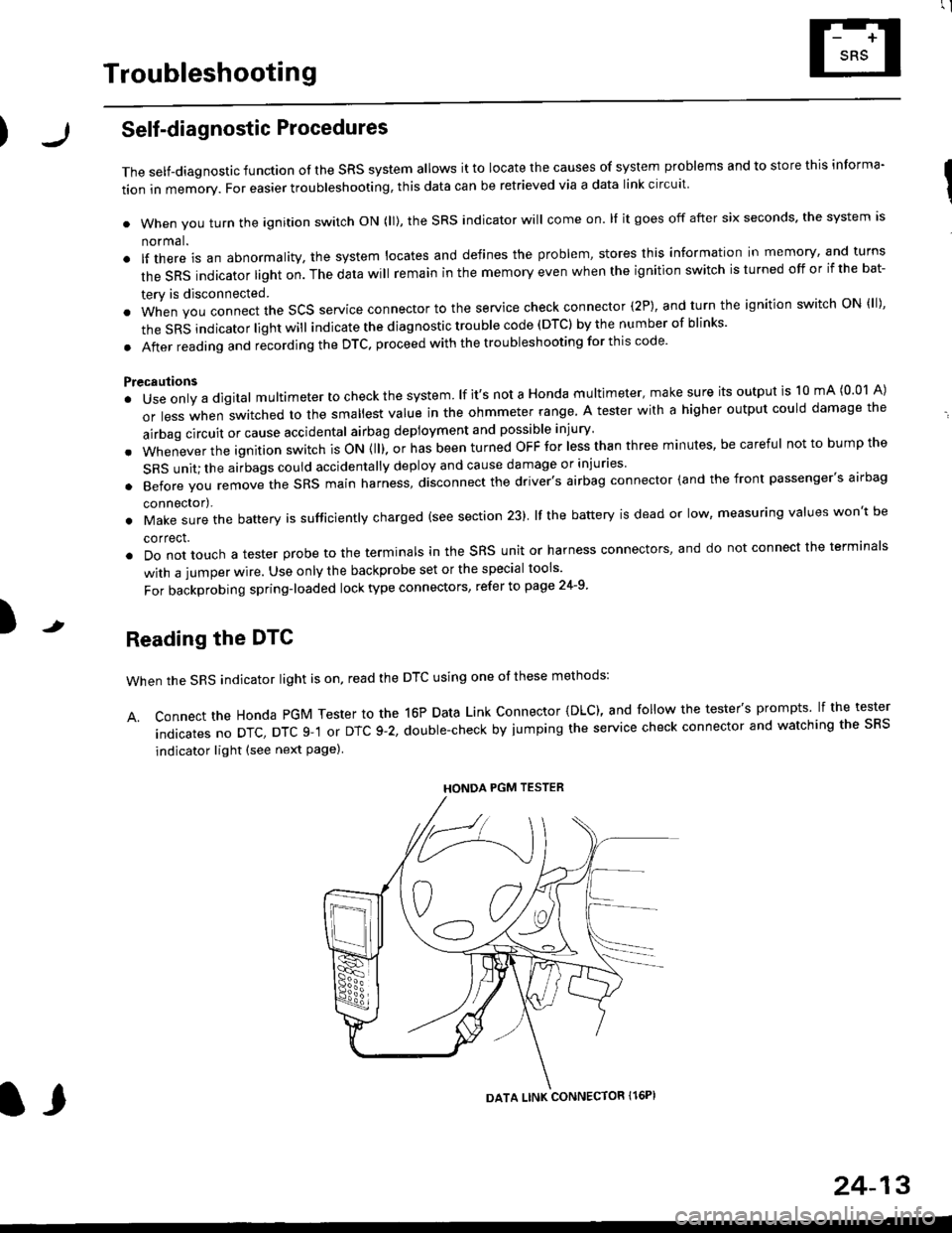
Reading the DTC
when the SRS indicator light is on, read the DTC using one of these methods:
A. Connect the Honda PGM Tester to the 16P Data Link Connector {DLC), and follow the tester's prompts lf the tester
indicatesnoDTc,DTcg-1orDTc9-2,doub|e-checkbyjumpingtheservicecheckconnectorandwatchingthesRS
indicator light (see next Page)
HONDA PGM TESTER
DATA LINK CONNECTOR Il6PI
l,
24-13