Page 1010 of 2189
Flywheel Housing
Input Shaft Oil Seal
l.
8. Install the oil seal in the transmission housing using
the sDecial tools as shown.
DRIVER07749 - 0010d)0
9.Install the oil seal in the flywheel housing using the
soecial tools as shown.
PILOT,26x30mmoTJAD - PH80200DRIVERATIACHMENT, 58 x 72 rnin
0?947 - d'40201
Replacement
1. Remove the input shaft oil seal from the flywheel
housing.
OIL SEAL
Instali the oil seal in the flywheel housing using the
soecialtools as shown.
FLYWHEEL
lmtalled depth:2.5- 3.5 mmro"nri':,ilii.rl
t@
14-333
Page 1011 of 2189

Transmission Housing Bearings
Driven Pulley Shaft Bearing Replacement
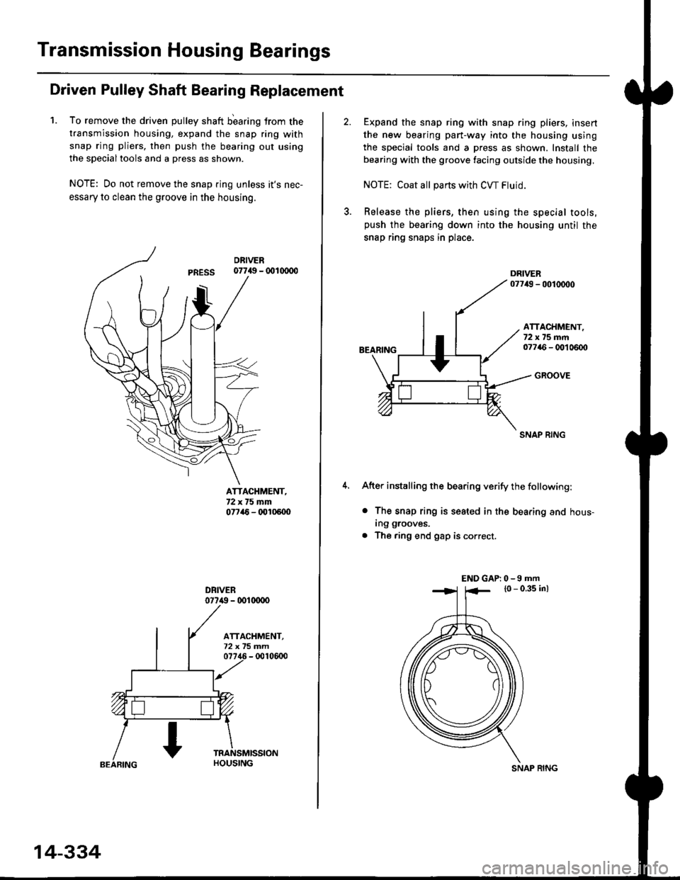
1. To remove the driven pulley shaft b'earing trom the
transmission housing, expand the snap ring with
snap ring pliers, then push the bearing out using
the specialtools and a press as shown.
NOTE: Do not remove the snap ring unless it's nec-
essary to clean the groove in the housing.
07749 - 001(xDo
ATTACHMENT,72x75mm07746 - (x'l05U)
077i() - 001(xrco
14-334
SNAP RING
Expand the snap ring with snap ring pliers, insert
the new bearing part-way into the housing using
the special tools and a press as shown. Install the
bearing with the groove facing outside the housing.
NOTE: Coat all pans with CW Fluid.
Release the pliers, then using the special tools,push the bearing down into the housing until the
snap ring snaps in place.
BEARING
ATTACHMENT,72x75mm07746 - OO1 0600
GROOVE
SNAP RING
After installing the bearing verify the following:
o The snap ring is seated in the bearing and hous-
ing grooves.
. The ring end gap is correct.
END GAP| 0 -9 mm
l0 - 0.35 inl
Page 1012 of 2189
Flywheel Housing
Bearing
Secondary Gear Shaft Bearing
Replacement
1. Remove the secondary gear shaft bearing using the
special tools as shown.
3/8" - 16 SLIDE HAMMER
{Comm6rciallY availablel
SECONDARY GEAR
ADJUSTABI.T BEARING SHAFT BEARINGPULLER.25 - 40 mm07736 - A01000A
Install the new secondary gear shaft bearing until it
bottoms in the transmission housing. using the spe-
cial tools as shown.
Secondary Gear Shaft Bearing
Replacement
1. Remove the secondary gear shaft bearing using the
soecial tool as shown.
3/8" - 16 SLIDE HAMMER
lCommorcially aY.ilabl6l
2. lnstall the new secondary gear shaft bearing until it
bottoms in the flywheel housing, using the special
tools as shown.
DRIVER07749 - (x)10000
ATTACHMENT.62xGgmm07745 - 0010500
14-335
Page 1013 of 2189
Ring Gear BearingControl Shaft Assembly
Replacement
1. Remove the ring gear bearing.
RING GEAR
Install the new ring gear bearing until it bottoms in
the ring gear. using the specialtools as shown,
DRIVER07?{9 - 001(xxxt
RING
14-336
RemovaUlnstallation
1. Remove the bolt and lock washer.
CONTROL SHAFTASSEMBLY
6r1.0mm14 N.ft 11.4 kg{.m,10 rbf.ftl
TRANSMISSION
CONTROLLEVER
LOCK WASHERReplace.
2. Remove the control lever from the control shaft.
3. Remove the control shaft assembly.
4. Install the control shaft assembly in the transmission
housing.
Install the control lever to the control shaft.
Install and tighten the bolt with a new lock washer.
Page 1028 of 2189

Transmission
Gooler Flushing
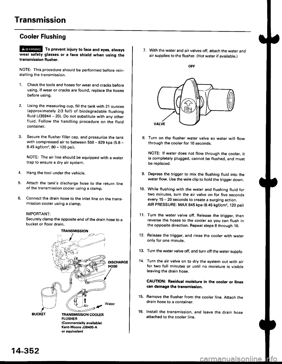
@ To prevent iniury to face and eyes, alwayswear safety glasses or a tace shield when using thetransmission flusher.
NOTE: This procedure should be performed before rein-stalling the transmission.
'1. Check the tools and hoses for wear and cracks before
using. lf wear or cracks are found, reDlace the hoses
before using.
4.
Using the measuring cup. fill the tank with 2,1 ounces(approximately 2/3 full) of biodegradable flushingfluid (J35944 - 20). Do not substitute with any otherfluid. Follow the handling procedure on the fluidcontatner.
Secure the flusher filler cap, and pressurize the tankwith compressed air to between 5S0 - 829 kpa (5.6 -
8.45 kgf/cm'�, 80 - 120 psi).
NOTE: The air line should be equipped with a watertrap to ensure a dry air system,
Hang the tool under the vehicle.
Attach the tank's discharge hose to the return lineoi the transmission cooler using a clamp.
Connect the drain hose to the inlet line on the trans-mission cooler using a clamp.
IMPORTANT:
Securely clamp the opposite end ofthe drain hose to abucket or floor drain,
t
TRANSMISSION COOLERFLUSHER{Commercially available)Kent-Moore J384O5-Aor oouivalent
TRANSMISSION
14-352
7. With the water and air valves off, attach the water andair supplies to the flusher. (Hot water if available.)
8. Turn on the flusher water valve so water will flowthrough the cooler for 10 seconds.
NOTE: lf water does not flow through the cooler, itis completely plugged, cannot be flushed, and mustbe replsced.
9. Depress the trigger to mix the flushing fluid into thewater flow. Use the wire clip to hold the trigger down.
'10. While flushing with the water and flushing fluid fortwo minutes. turn the air valve on for five secondsevery 15 - 20 seconds to create a surging action.AIR PRESSURE: MAX 845 kpa (8.45 kgflcmr, 120 psi)
11. Turn the water valve off. Release the trigger, thenreverse the hoses to the cooler so you can flush inthe opposite direction. Repeat steps 8 through 10.
12. Release the trigger. and rinse the cooler with wateronly for one minute.
13, Turn the water valve off, and turn off the water supply.
'14. Turn the air valve on to dry the system out with airfor two full minutes or until no moisture is visibleleaving the drain hose.
CAUTION: Rosidual mobturo in the qooler or linescln damage the transmission,
15. Remove the flusher from the cooler line. Attach thedrain hose to a container.
16. Install the transmission. and leave the drain hoseattached to the cooler line.
Page 1035 of 2189
Special Tools
Ref. No. I Tool NumberDescriptionOty I Remark
o
@,a
\9'
o
@
@
07JAF - SH20400
07LAD - PW50601
07MAC - S100200
07746 - 0010300
07746 - 0010400
07746 - 0030400
07749 - 0010000
07965 - SD90100
07xAc - 0010100
Support Base Attachment
Inner Race Driver
Ball Joint Remover, 28 mm
Driver Attachment, 42 x 47 mm
Driver Attachment, 52 x 55 mm
Driver Attachment, 35 mm l.D.
Handle Driver
Support Base
Threaded Adapter, 22 x 1.5 mm
1
1
1
1
I
I
1
I
1
@e
@
&
w
@
@
c
6
@
'
lo,
c[G)
8-)
ge
l..---,l
G)
16-2
Page 1054 of 2189

Disassembly
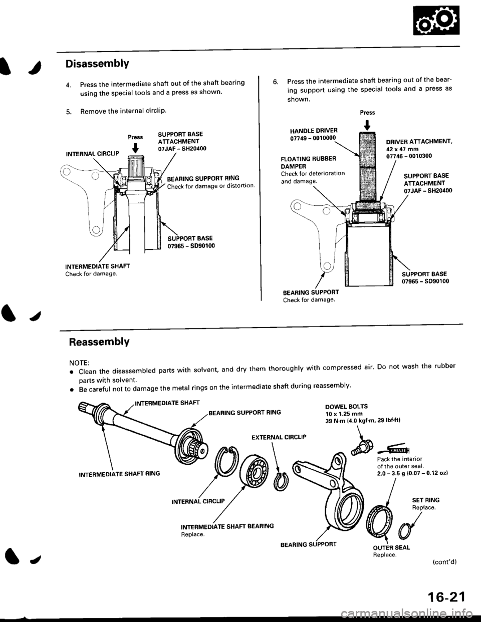
Press the intermediate shaft out of the shaft bearing
using the special tools and a press as shown.
Remove the internal circliP
Press
I
SUPPORT BASEATTACHMENT07JAF - SH20400INTERNAL CIBCLIP
BEARING SUPPORT RING
Check for damage or distortion
6. Press the intermediate shaft bearing out ot the bear-
ing support using the special tools and a press as
shown.
HANOLE DRIVER
0?749 - 00'�10000
Press
I
DRIVER ATTACHMENT,12x47 mm07746 - 0010300FLOATING RUBBEB
DAMPERCheck for deterioration
and oamage.SUPPORT BASE
ATTACHMENT07JAF _ SH20it00
BEARING SUPPORT
Check for damage
I sErR'NG
A4 Reolace
VUOUTER SEALReplace.(cont'd)
ReassemblY
NOTE:
. clean the disassembted parts with solvent, and dry them thoroughly with compressed air' Do not wash the rubber
parts with solvent.
. Becareful not to da mage the metal ringson the intermediate shaftduring reassembly'
BEARING SUPPORT RINGDOWEL BOLTS10 x 1.25 mm39 N.m 14.0 kgf.m,29 lbIftl
EXTERNAL CIRCLIP
Pack the interiorof the outer seal.2.0-35s10.07-012oz)
INTERNAL CIRCLIP
INTERMEDTATE SHAFT BEARING
Replace,
INTERMEDIATE SHAFT RING
lJ
16-21
Page 1055 of 2189
lntermediate Shaft
Reassembly (cont'd)
1. Press the intermediate shaft bearing into the bear-ing support using the special tools and a press asshown.
Prass
I
DRIVER ATTACHMENT,52x55mm07746 - 001 0(X)
Seat the internal circlip in the groove of the bearingsuppon.
Press the intermediate shaft into the shaft bearingusing the special tools and a press.
Praa.r
I
@---
LJ
INTERMEDIATE SHAFT
DRIVER ATTACHMENT,35 mm LD.
16-22
Seat the external circlip in the groove of the inter-mediate shaft.
Install the outer seal into the bearing support usingthe special tools as shown.
NOTE: Install the seal ftush with the bearing sup-port.
Pre$
t HANDr.r DRTVER- 0011r(x)0
Pack the Interiorof the ouler seal.2.0- 3.5 g {0.07 -0.12 ozl
OUTEN SEAL
Install the new set ringgroove.
ORIVER ATTACHMENT,52x55mm077i16 - 0010/O0
in the intermediate shaft