1996 CHRYSLER VOYAGER oil pressure
[x] Cancel search: oil pressurePage 1066 of 1938
sealing and a chrome plated taper faced intermediate
ring for additional cylinder pressure control. There
are also standard oil control rings.
CYLINDER HEAD:Features a Dual Over Head
Camshaft (DOHC) 4 valves per cylinder cross flow
design. The valves are arranged in two inline banks,
with the ports of the bank of two intake valves per
cylinder facing toward the radiator side of engine
and ports of the bank of two exhaust valves per cyl-
inder facing toward the dash panel. Incorporates
powder metal valve guides and seats. Integral oil gal-
leys within the cylinder head supplies oil to the
hydraulic lash adjusters, camshaft and valve mecha-
nisms.
CAMSHAFTS:The nodular iron camshafts have
six bearing journals and 2 cam lobes per cylinder.
Flanges at the rear journals control camshaft end
play. Provision for cam position sensor is located on
the intake camshaft at the rear of cylinder head. A
hydrodynamic oil seal is used for oil control at the
front of the camshaft.
VALVES:4 valves per cylinder are actuated by
roller cam followers which pivot on stationary
hydraulic lash adjusters. All valves have 6 mm diam-
eter chrome plated valve stems. The valve sizes are
34.8 mm (1.370 inch.) diameter intake valves and
30.5 mm (1.20 inch.) diameter exhaust valves. Viton
rubber valve stem seals are integral with the spring
seats. Valve springs, spring retainers, and locks are
conventional.
INTAKE MANIFOLD:The intake manifold is a
two piece aluminum casting, attached to the cylinder
head with ten screws. This long branch fan design
enhances low and midspeed torque, while minimizing
undesirable inlet noise.
EXHAUST MANIFOLD:The exhaust manifold is
made of cast iron for strength and high tempera-
tures.
ENGINE LUBRICATION:Refer to Group 0
Lubrication and Maintenance for recommended oil to
be used in various engine application. System is full
flow filtration, pressure feed type. The oil pump is
mounted in the front engine cover and driven by the
crankshaft. Pressurized oil is then routed through
the main oil gallery, running the length of the cylin-
der block, supplying main and rod bearings with fur-
ther routing. Pistons are lubricated from rod bearing
throw off and lubricating slots on the connecting rod
assemblies. Camshaft and valve mechanisms are
lubricated from a full length cylinder head oil gallery
supplied from the crankcase main oil gallery.DIAGNOSIS AND TESTING
CHECKING ENGINE OIL PRESSURE
(1) Remove oil pressure sending unit and install
gauge assembly C-3292.
(2) Run engine until thermostat opens.
CAUTION: If oil pressure is 0 at idle, Do Not Run
engine at 3000 RPM
(3) Oil Pressure:Curb Idle25 kPa (4 psi) mini-
mum3000 RPM170/550 kPa (25/80 psi).
(4) If oil pressure is 0 at idle. Shut off engine,
check for pressure relief valve stuck open or a
clogged oil pickup screen.
SERVICE PROCEDURES
FITTING PISTONS
Piston and cylinder wall must be clean and dry.
Piston diameter should be measured 90 degrees to
piston pin about 14 mm (9/16 inch.) from the bottom
of the skirt as shown in (Fig. 3). Cylinder bores
should be measured halfway down the cylinder bore
and transverse to the engine crankshaft center line
shown in (Fig. 2). Refer to Cylinder Bore and Piston
Specification Chart.
Correct piston to bore clearance must be estab-
lished in order to assure quiet and economical oper-
ation.
Chrysler engines use pistons designed specifically
for each engine model. Clearance and sizing locations
vary with respect to engine model.
NOTE: Pistons and cylinder bores should be mea-
sured at normal room temperature, 70ÉF (21ÉC).
FITTING PISTON RINGS
(1) Wipe cylinder bore clean. Insert ring and push
down with piston to ensure it is square in bore. The
ring gap measurement must be made with the ring
positioning at least 12 mm (0.50 inch) from bottom of
cylinder bore. Check gap with feeler gauge (Fig. 4).
Refer to specification in Piston Ring Specification
Chart.
(2) Check piston ring to groove side clearance (Fig.
5). Refer to specification in Piston Ring Specification
Chart.
9 - 16 2.4L ENGINENS
DESCRIPTION AND OPERATION (Continued)
Page 1076 of 1938
ENGINE ASSEMBLY
REMOVAL
(1) Perform fuel pressure release procedure. Refer
to Group 14, Fuel System for procedure. Remove fuel
line to fuel rail.
(2) Disconnect battery.
(3) Remove Air cleaner and hoses.
(4) Drain cooling system. Refer to Group 7, Cooling
System for procedure.
(5) Remove upper radiator hose and remove radia-
tor fans. Refer to Group 7, Cooling System for proce-
dure.
(6) Remove lower radiator hose.
(7) Disconnect automatic transmission cooler lines
and plug, if equipped.
(8) Disconnect transmission shift linkage.
(9) Disconnect throttle body linkage.
(10) Disconnect engine wiring harness.
(11) Disconnect heater hoses.
(12) Discharge Air Conditioning System. Refer to
Group 24, Air Conditioning for procedure.
(13) Hoist vehicle and remove right inner splash
shield. Remove wheels and tires.
(14) Loosen power steering belt for pump removal.
Refer to Group 7, Cooling System for procedure.
(15) Remove axle shafts. Refer to Group 2, Suspen-
sion and Driveshafts for procedure.
(16) Disconnect exhaust pipe from manifold.
(17) Remove front and rear engine mount brackets
from the body.
(18) Remove bending braces and front engine
mount bracket. Remove transmission inspection
cover.
(19) Mark flexplate to torque converter and
remove torque converter bolts.
(20) Install front engine mount bracket.
(21) Lower vehicle.
(22) Remove power steering pump. Set pump
aside.
(23) Remove A/C lines at compressor and cap.
(24) Remove ground straps to body.
(25) Raise vehicle enough to allow engine dolly
Special Tool 6135, cradle Special Tool 6710 with
Posts Special Tool 6848 and Adaptor Special Tool
8130 to be installed under vehicle (Fig. 27).
(26) Loosen cradle posts to allow movement for
proper positioning. Locate two rear posts (right side
of engine) into the holes on the engine bedplate.
Locate the two front posts (left side of engine) on the
front engine bracket and A/C compressor bracket
(Fig. 27). Lower vehicle and position cradle mounts
until the engine is resting on mounts. Tighten
mounts to cradle frame. This will keep mounts from
moving when removing or installing engine and
transmission.(27) Lower vehicle so the weight ofONLY THE
ENGINE AND TRANSMISSIONare on the cradle.
(28) Remove engine and transmission mount bolts.
(29) Raise vehicle slowly. It may be necessary to
move the engine/transmission assembly on the cradle
to allow for removal around the body.
INSTALLATION
(1) Position engine and transmission assembly
under vehicle and slowly lower the vehicle over the
engine and transmission.
(2) Align engine and transmission mounts to
attaching points. Install mounting bolts at the right
engine and left transmission mounts. Refer to proce-
dures outlined in this section.
(3) Slowly raise vehicle enough to remove the
engine dolly and cradle Special Tools 6135 and 6710.
(4) Install axle shafts. Refer to Group 2, Suspen-
sion and Driveshafts for procedure.
(5) Install transmission and engine braces and
splash shields.
(6) Connect exhaust system to manifold. Refer to
Group 11, Exhaust System and Intake Manifold for
procedure and torque specifications.
(7) Install power steering pump. Refer to Cooling
System Group 7, Accessory Drive Section for belt ten-
sion adjustment.
(8) Install A/C compressor hoses. Refer to Group
24, Heater and Air Conditioning for procedure.
(9) Install accessory drive belts. Refer to Group 7,
Cooling System Accessory Drive Section for belt ten-
sion adjustment.
(10) Install front and rear engine mounts. Refer to
this section for procedure.
(11) Install inner splash shield. Install wheels and
tires.
(12) Connect automatic transmission cooler lines,
and shift linkage. Refer to Group 21, Transmission
for procedures.
(13) Connect fuel line and heater hoses.
(14) Install ground straps. Connect engine and
throttle body connections and harnesses. Refer to
Group 8, Electrical for procedure.
(15) Connect throttle body linkage. Refer to Group
14, Fuel System for procedure.
(16) Install radiator fans. Install radiator hoses.
Fill cooling system. Refer to Group 7, Cooling System
for filling procedure.
(17) Connect battery.
(18) Install air cleaner and hoses.
(19) Install oil filter. Fill engine crankcase with
proper oil to correct level.
(20) Start engine and run until operating temper-
ature is reached.
(21) Adjust transmission linkage, if necessary.
9 - 26 2.4L ENGINENS
REMOVAL AND INSTALLATION (Continued)
Page 1083 of 1938
NOTE: THE TIMING MARK ON THE SPROCKET,
THE (LOWER) NICKEL PLATED LINK, AND THE
ARROW ON THE SIDE OF THE GEAR COVER
SHOULD LINE UP WHEN THE BALANCE SHAFTS
ARE TIMED CORRECTLY.
(9) If the sprockets are timed correctly install the
balance shaft bolts and tighten to 28 N´m (250 in.
lbs.). A wood block placed between crankcase and
crankshaft counterbalance will prevent crankshaft
and gear rotation.
CHAIN TENSIONING
(1) Install chain tensioner loosely assembled.
(2) Position guide on double ended stud making
sure tab on the guide fits into slot on the gear cover.
Install and tighten nut/washer assembly to 12 N´m
(105 in. lbs.).
(3) Place a shim 1 mm (0.039 in.) thick x 70 mm
(2.75 in.) long or between tensioner and chain. Push
tensioner and shim up against the chain.Apply firm
pressure (5.5 to 6.6 lbs.) directly behind the
adjustment slot to take up all slack.Chain must
have shoe radius contact as shown in (Fig. 46).
(4) With the load applied, tighten top tensioner
bolt first, then bottom pivot bolt. Tighten bolts to 12
N´m (105 in. lbs.). Remove shim.
(5) Install carrier covers and tighten screws to 12
N´m (105 in. lbs.).HYDRAULIC LASH ADJUSTER
REMOVAL
(1) Remove cylinder head cover. Refer to procedure
outlined in this section.
(2) Remove cam follower assembly. Refer to cam-
shaft removal procedure outlined in this section to
gain access to cam followers and lash adjusters.
(3) Mark hydraulic lash adjusters for reassembly
in their original position. Lash adjusters are serviced
as an assembly.
INSTALLATION
(1) Install hydraulic lash adjuster assembly mak-
ing sure adjusters are at least partially full of oil.
This is indicated by little or no plunger travel when
the lash adjuster is depressed.
(2) Install cam follower assembly as previously
outlined in this section.
(3) Install camshaft as previously outlined in this
section.
(4) Install cylinder head cover as previously out-
lined in this section.
VALVE SPRINGS AND VALVE SEALS IN VEHICLE
REMOVAL
(1) Remove camshafts as previously outlined in
this section.
(2) Rotate crankshaft until piston is at TDC on
compression.
(3) With air hose attached to adapter tool
installed in spark plug hole, apply 90-120 psi air
pressure.
(4) Using Special Tool MD-998772-A with adapter
6779 (Fig. 47) compress valve springs and remove
valve locks.
(5) Remove valve spring.
(6) Remove valve stem seal by a using valve stem
seal tool.
INSTALLATION
(1) Install valve seal/valve spring seat assembly
(Fig. 48). Push the assembly down to seat it onto the
valve guide.
(2) Install valve spring and retainer, use Special
Tool MD-998772-A with adapter 6779 to compress
valve springs only enough to install locks (Fig. 47).
Correct alignment of tool is necessary to avoid nick-
ing valve stems.
(3) Remove air hose and install spark plugs.
(4) Install camshafts as previously outlined in this
section.
(5) Install cylinder head cover as previously out-
lined in this section.
Fig. 46 Chain Tension Adjustment
NS2.4L ENGINE 9 - 33
REMOVAL AND INSTALLATION (Continued)
Page 1084 of 1938
CYLINDER HEAD
REMOVAL
(1) Perform fuel system pressure release proce-
durebefore attempting any repairs.Refer to
Group 14, Fuel System for procedure.
(2) Disconnect negative battery cable. Drain cool-
ing system. Refer to Group 7, Cooling System for pro-
cedure.
(3) Remove air cleaner and disconnect all vacuum
lines, electrical wiring and fuel lines from throttle
body.
(4) Remove throttle linkage. Refer to Group 14,
Fuel System for procedures
(5) Remove accessory drive belts. Refer to Group
7, Cooling System for procedure.
(6) Remove power brake vacuum hose from intake
manifold.
(7) Raise vehicle and remove exhaust pipe from
manifold.(8) Remove power steering pump assembly and
set aside.
(9) Disconnect coil pack wiring connector and
remove coil pack and plug wires from engine.
(10) Remove cam sensor and fuel injectors wiring
connectors.
(11) Remove timing belt and camshaft sprocket.
Refer to procedure outlined in this section.
(12) Remove timing belt idler pulley and rear tim-
ing belt cover.
(13) Remove cylinder head cover using procedure
outlined in this section.
(14) Remove camshafts and cam followers. Refer to
procedures outlined in this section for procedures.
(15) Remove cylinder head bolts and remove cyl-
inder head from engine block.
(16) Inspect and clean cylinder head. Refer to
Cleaning and Inspection outlined in this section for
procedures.
INSTALLATION
NOTE: The Cylinder head bolts should be exam-
ined BEFORE reuse. If the threads are necked
down, the bolts should be replaced (Fig. 49).
Necking can be checked by holding a scale or
straight edge against the threads. If all the threads
do not contact the scale the bolt should be replaced.
(1) Before installing the bolts, the threads should
be coated with engine oil.
(2) Tighten the cylinder head bolts in the
sequence shown in (Fig. 50). Using the 4 step torque
turn method, tighten according to the following val-
ues:
²First All to 34 N´m (25 ft. lbs.)
²Second All to 68 N´m (50 ft. lbs.)
²Third All to 68 N´m (50 ft. lbs.)
CAUTION: Do not use a torque wrench for the fol-
lowing step.
²Fourth Turn an additional 1/4 Turn,
(3) Install camshafts and cam followers. Refer to
procedures outlined in this section for procedures.
Fig. 47 Valve SpringÐRemoval/Installation
Fig. 48 Valve Stem Seal/Valve Spring Seat
Fig. 49 Checking Bolts for Stretching (Necking)
9 - 34 2.4L ENGINENS
REMOVAL AND INSTALLATION (Continued)
Page 1100 of 1938
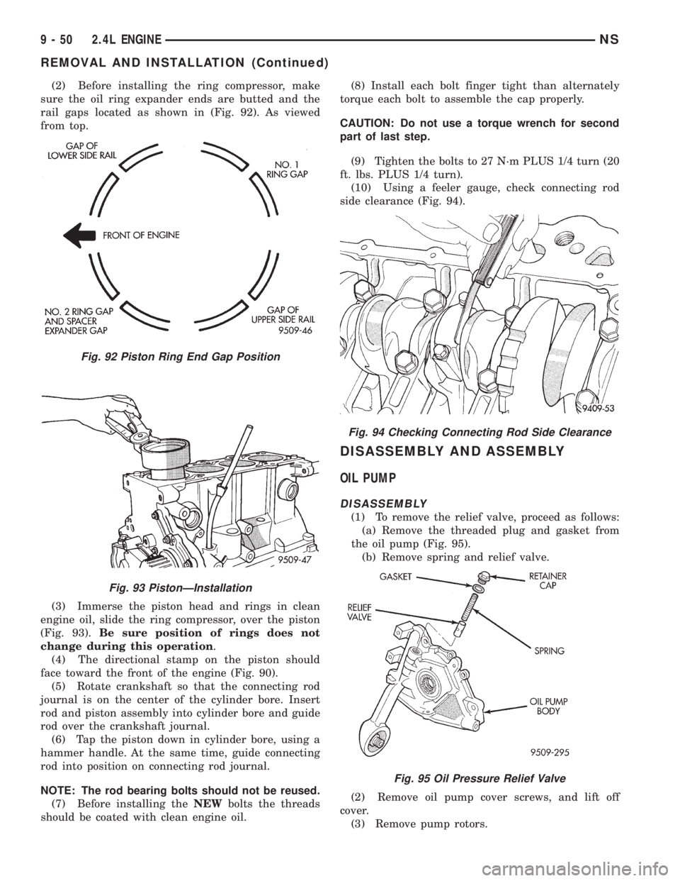
(2) Before installing the ring compressor, make
sure the oil ring expander ends are butted and the
rail gaps located as shown in (Fig. 92). As viewed
from top.
(3) Immerse the piston head and rings in clean
engine oil, slide the ring compressor, over the piston
(Fig. 93).Be sure position of rings does not
change during this operation.
(4) The directional stamp on the piston should
face toward the front of the engine (Fig. 90).
(5) Rotate crankshaft so that the connecting rod
journal is on the center of the cylinder bore. Insert
rod and piston assembly into cylinder bore and guide
rod over the crankshaft journal.
(6) Tap the piston down in cylinder bore, using a
hammer handle. At the same time, guide connecting
rod into position on connecting rod journal.
NOTE: The rod bearing bolts should not be reused.
(7) Before installing theNEWbolts the threads
should be coated with clean engine oil.(8) Install each bolt finger tight than alternately
torque each bolt to assemble the cap properly.
CAUTION: Do not use a torque wrench for second
part of last step.
(9) Tighten the bolts to 27 N´m PLUS 1/4 turn (20
ft. lbs. PLUS 1/4 turn).
(10) Using a feeler gauge, check connecting rod
side clearance (Fig. 94).
DISASSEMBLY AND ASSEMBLY
OIL PUMP
DISASSEMBLY
(1) To remove the relief valve, proceed as follows:
(a) Remove the threaded plug and gasket from
the oil pump (Fig. 95).
(b) Remove spring and relief valve.
(2) Remove oil pump cover screws, and lift off
cover.
(3) Remove pump rotors.
Fig. 92 Piston Ring End Gap Position
Fig. 93 PistonÐInstallation
Fig. 94 Checking Connecting Rod Side Clearance
Fig. 95 Oil Pressure Relief Valve
9 - 50 2.4L ENGINENS
REMOVAL AND INSTALLATION (Continued)
Page 1101 of 1938
(4) Wash all parts in a suitable solvent and
inspect carefully for damage or wear.
ASSEMBLY
(1) Assemble pump, using new parts as required.
Install the inner rotor with chamfer facing the
cast iron oil pump cover.
(2) Prime oil pump before installation by filling
rotor cavity with engine oil.
(3) Install cover and tighten screws to 12 N´m
(105 in. lbs.).
CAUTION: Oil pump pressure relief valve must be
installed as shown in (Fig. 95) or serious damage
may occur.
(4) Install relief valve, spring, gasket and cap as
shown in (Fig. 95). Tighten cap to 41 N´m (30 ft. lbs.)
CLEANING AND INSPECTION
CYLINDER HEAD
CLEANING
Remove all gasket material from cylinder head and
block. Be careful not to gouge or scratch the alumi-
num head sealing surface.
INSPECTION
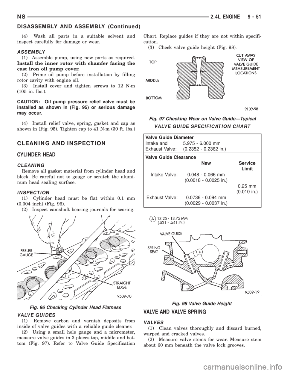
(1) Cylinder head must be flat within 0.1 mm
(0.004 inch) (Fig. 96).
(2) Inspect camshaft bearing journals for scoring.
VALVE GUIDES
(1) Remove carbon and varnish deposits from
inside of valve guides with a reliable guide cleaner.
(2) Using a small hole gauge and a micrometer,
measure valve guides in 3 places top, middle and bot-
tom (Fig. 97). Refer to Valve Guide SpecificationChart. Replace guides if they are not within specifi-
cation.
(3) Check valve guide height (Fig. 98).
VALVE AND VALVE SPRING
VALVES
(1) Clean valves thoroughly and discard burned,
warped and cracked valves.
(2) Measure valve stems for wear. Measure stem
about 60 mm beneath the valve lock grooves.
Fig. 96 Checking Cylinder Head Flatness
Fig. 97 Checking Wear on Valve GuideÐTypical
VALVE GUIDE SPECIFICATION CHART
Valve Guide Diameter
Intake and
Exhaust Valve:5.975 - 6.000 mm
(0.2352 - 0.2362 in.)
Valve Guide Clearance
New Service
Limit
Intake Valve: 0.048 - 0.066 mm
(0.0018 - 0.0025 in.)
0.25 mm
(0.010 in.)
Exhaust Valve: 0.0736 - 0.094 mm
(0.0029 - 0.0037 in.)
Fig. 98 Valve Guide Height
NS2.4L ENGINE 9 - 51
DISASSEMBLY AND ASSEMBLY (Continued)
Page 1103 of 1938
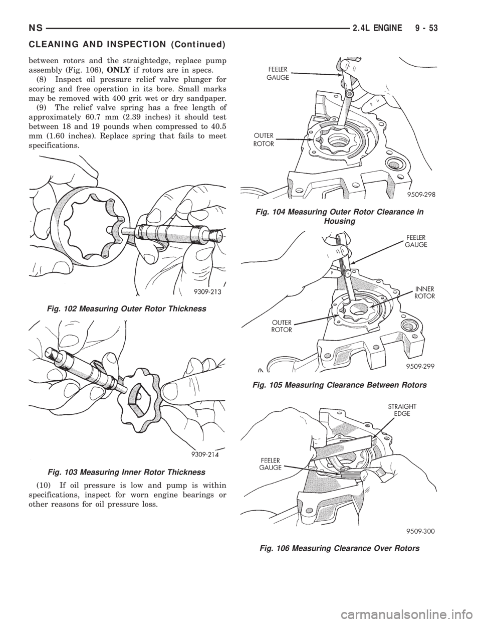
between rotors and the straightedge, replace pump
assembly (Fig. 106),ONLYif rotors are in specs.
(8) Inspect oil pressure relief valve plunger for
scoring and free operation in its bore. Small marks
may be removed with 400 grit wet or dry sandpaper.
(9) The relief valve spring has a free length of
approximately 60.7 mm (2.39 inches) it should test
between 18 and 19 pounds when compressed to 40.5
mm (1.60 inches). Replace spring that fails to meet
specifications.
(10) If oil pressure is low and pump is within
specifications, inspect for worn engine bearings or
other reasons for oil pressure loss.
Fig. 102 Measuring Outer Rotor Thickness
Fig. 103 Measuring Inner Rotor Thickness
Fig. 104 Measuring Outer Rotor Clearance in
Housing
Fig. 105 Measuring Clearance Between Rotors
Fig. 106 Measuring Clearance Over Rotors
NS2.4L ENGINE 9 - 53
CLEANING AND INSPECTION (Continued)
Page 1105 of 1938
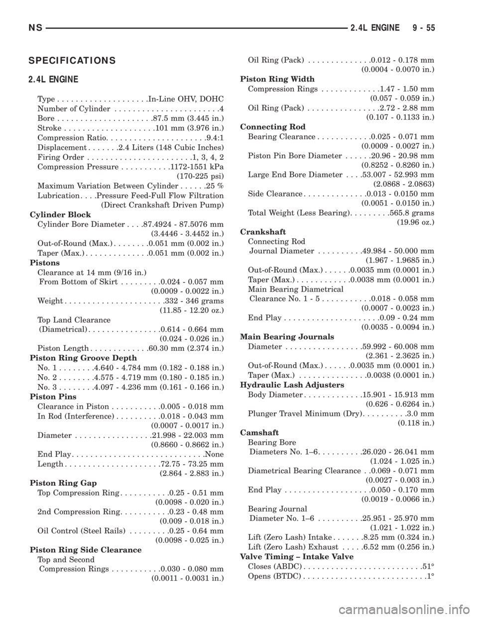
SPECIFICATIONS
2.4L ENGINE
Type....................In-Line OHV, DOHC
Number of Cylinder.......................4
Bore.....................87.5 mm (3.445 in.)
Stroke....................101 mm (3.976 in.)
Compression Ratio......................9.4:1
Displacement.......2.4 Liters (148 Cubic Inches)
Firing Order.......................1,3,4,2
Compression Pressure...........1172-1551 kPa
(170-225 psi)
Maximum Variation Between Cylinder......25%
Lubrication. . . .Pressure Feed-Full Flow Filtration
(Direct Crankshaft Driven Pump)
Cylinder Block
Cylinder Bore Diameter. . . .87.4924 - 87.5076 mm
(3.4446 - 3.4452 in.)
Out-of-Round (Max.)........0.051 mm (0.002 in.)
Taper (Max.)..............0.051 mm (0.002 in.)
Pistons
Clearance at 14 mm (9/16 in.)
From Bottom of Skirt.........0.024 - 0.057 mm
(0.0009 - 0.0022 in.)
Weight......................332 - 346 grams
(11.85 - 12.20 oz.)
Top Land Clearance
(Diametrical)................0.614 - 0.664 mm
(0.024 - 0.026 in.)
Piston Length.............60.30 mm (2.374 in.)
Piston Ring Groove Depth
No.1........4.640 - 4.784 mm (0.182 - 0.188 in.)
No.2........4.575 - 4.719 mm (0.180 - 0.185 in.)
No.3........4.097 - 4.236 mm (0.161 - 0.166 in.)
Piston Pins
Clearance in Piston...........0.005 - 0.018 mm
In Rod (Interference)..........0.018 - 0.043 mm
(0.0007 - 0.0017 in.)
Diameter.................21.998 - 22.003 mm
(0.8660 - 0.8662 in.)
End Play.............................None
Length.....................72.75 - 73.25 mm
(2.864 - 2.883 in.)
Piston Ring Gap
Top Compression Ring...........0.25 - 0.51 mm
(0.0098 - 0.020 in.)
2nd Compression Ring...........0.23 - 0.48 mm
(0.009 - 0.018 in.)
Oil Control (Steel Rails).........0.25 - 0.64 mm
(0.0098 - 0.025 in.)
Piston Ring Side Clearance
Top and Second
Compression Rings...........0.030 - 0.080 mm
(0.0011 - 0.0031 in.)Oil Ring (Pack)..............0.012 - 0.178 mm
(0.0004 - 0.0070 in.)
Piston Ring Width
Compression Rings.............1.47 - 1.50 mm
(0.057 - 0.059 in.)
Oil Ring (Pack)................2.72 - 2.88 mm
(0.107 - 0.1133 in.)
Connecting Rod
Bearing Clearance............0.025 - 0.071 mm
(0.0009 - 0.0027 in.)
Piston Pin Bore Diameter......20.96 - 20.98 mm
(0.8252 - 0.8260 in.)
Large End Bore Diameter. . . .53.007 - 52.993 mm
(2.0868 - 2.0863)
Side Clearance..............0.013 - 0.0150 mm
(0.0051 - 0.0150 in.)
Total Weight (Less Bearing).........565.8 grams
(19.96 oz.)
Crankshaft
Connecting Rod
Journal Diameter..........49.984 - 50.000 mm
(1.967 - 1.9685 in.)
Out-of-Round (Max.)......0.0035 mm (0.0001 in.)
Taper (Max.)............0.0038 mm (0.0001 in.)
Main Bearing Diametrical
Clearance No.1-5...........0.018 - 0.058 mm
(0.0007 - 0.0023 in.)
End Play.....................0.09 - 0.24 mm
(0.0035 - 0.0094 in.)
Main Bearing Journals
Diameter.................59.992 - 60.008 mm
(2.361 - 2.3625 in.)
Out-of-Round (Max.)......0.0035 mm (0.0001 in.)
Taper (Max.)...............0.0038 (0.0001 in.)
Hydraulic Lash Adjusters
Body Diameter.............15.901 - 15.913 mm
(0.626 - 0.6264 in.)
Plunger Travel Minimum (Dry)..........3.0 mm
(0.118 in.)
Camshaft
Bearing Bore
Diameters No. 1±6..........26.020 - 26.041 mm
(1.024 - 1.025 in.)
Diametrical Bearing Clearance . .0.069 - 0.071 mm
(0.0027 - 0.003 in.)
End Play...................0.050 - 0.170 mm
(0.0019 - 0.0066 in.)
Bearing Journal
Diameter No. 1±6..........25.951 - 25.970 mm
(1.021 - 1.022 in.)
Lift (Zero Lash) Intake.......8.25 mm (0.324 in.)
Lift (Zero Lash) Exhaust.....6.52 mm (0.256 in.)
Valve Timing ± Intake Valve
Closes (ABDC)..........................51É
Opens (BTDC)...........................1É
NS2.4L ENGINE 9 - 55