1996 CHRYSLER VOYAGER oil pressure
[x] Cancel search: oil pressurePage 1106 of 1938
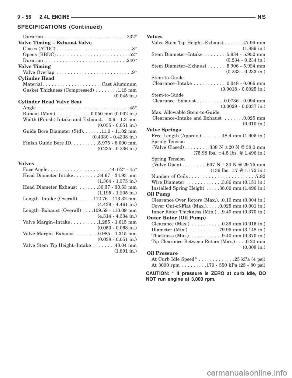
Duration.............................232É
Valve Timing ± Exhaust Valve
Closes (ATDC)...........................8É
Opens (BBDC)..........................52É
Duration.............................240É
Valve Timing
Valve Overlap...........................9É
Cylinder Head
Material.....................Cast Aluminum
Gasket Thickness (Compressed)........1.15 mm
(0.045 in.)
Cylinder Head Valve Seat
Angle.................................45É
Runout (Max.).............0.050 mm (0.002 in.)
Width (Finish) Intake and Exhaust. . .0.9 - 1.3 mm
(0.035 - 0.051 in.)
Guide Bore Diameter (Std).......11.0-11.02 mm
(0.4330 - 0.4338 in.)
Finish Guide Bore ID..........5.975 - 6.000 mm
(0.235 - 0.236 in.)
Valves
Face Angle......................44-1/2É - 45É
Head Diameter Intake.........34.67 - 34.93 mm
(1.364 - 1.375 in.)
Head Diameter Exhaust.......30.37 - 30.63 mm
(1.195 - 1.205 in.)
Length±Intake (Overall)......112.76 - 113.32 mm
(4.439 - 4.461 in.)
Length±Exhaust (Overall). . . .109.59 - 110.09 mm
(4.314 - 4.334 in.)
Valve Margin±Intake..........1.285 - 1.615 mm
(0.050 - 0.063 in.)
Valve Margin±Exhaust........0.985 - 1.315 mm
(0.038 - 0.051 in.)
Valve Stem Tip Height±Intake........48.04 mm
(1.891 in.)Valves
Valve Stem Tip Height±Exhaust.......47.99 mm
(1.889 in.)
Stem Diameter±Intake........5.934 - 5.952 mm
(0.234 - 0.234 in.)
Stem Diameter±Exhaust.......5.906 - 5.924 mm
(0.233 - 0.233 in.)
Stem-to-Guide
Clearance±Intake............0.048 - 0.066 mm
(0.0018 - 0.0025 in.)
Stem-to-Guide
Clearance±Exhaust..........0.0736 - 0.094 mm
(0.0029 - 0.0037 in.)
Max. Allowable Stem-to-Guide
Clearance±Intake and Exhaust.......0.025 mm
(0.010 in.)
Valve Springs
Free Length (Approx.).......48.4 mm (1.905 in.)
Spring Tension
(Valve Closed).........338 N620 N @ 38.0 mm
(75.98 lbs.64.5 lbs. @ 1.496 in.)
Spring Tension
(Valve Open).........607 N630 N @ 29.75 mm
(136 lbs.67 @ 1.172 in.)
Number of Coils........................7.82
Wire Diameter.............3.86 mm (0.151 in.)
Installed Spring Height.....38.00 mm (1.496 in.)
Oil Pump
Clearance Over Rotors (Max.). .0.10 mm (0.004 in.)
Cover Out-of-Flat (Max.).....0.025 mm (0.001 in.)
Inner Rotor Thickness (Min.) . .9.40 mm (0.370 in.)
Outer Rotor (Oil Pump)
Clearance (Max.)...........0.39 mm (0.015 in.)
Diameter (Min.)...........79.95 mm (3.148 in.)
Thickness (Min.)............9.40 mm (0.370 in.)
Tip Clearance Between Rotors (Max.). . . .0.20 mm
(0.008 in.)
Oil Pressure
At Curb Idle Speed*.............25kPa(4psi)
At 3000 rpm.........170 - 550 kPa (25 - 80 psi)
CAUTION: * If pressure is ZERO at curb Idle, DO
NOT run engine at 3,000 rpm.
9 - 56 2.4L ENGINENS
SPECIFICATIONS (Continued)
Page 1110 of 1938
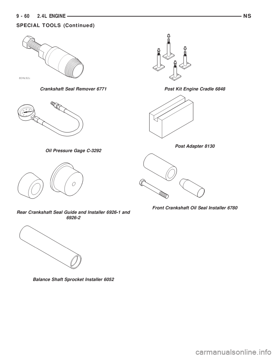
Crankshaft Seal Remover 6771
Oil Pressure Gage C-3292
Rear Crankshaft Seal Guide and Installer 6926-1 and
6926-2
Balance Shaft Sprocket Installer 6052
Post Kit Engine Cradle 6848
Post Adapter 8130
Front Crankshaft Oil Seal Installer 6780
9 - 60 2.4L ENGINENS
SPECIAL TOOLS (Continued)
Page 1111 of 1938
3.0L ENGINE
INDEX
page page
DESCRIPTION AND OPERATION
ENGINE COMPONENTS.................. 61
ENGINE IDENTIFICATION NUMBER......... 61
ENGINE LUBRICATION................... 61
DIAGNOSIS AND TESTING
CHECKING ENGINE OIL PRESSURE......... 62
SERVICE PROCEDURES
AUTO LASH ADJUSTER................... 62
CHECKING CRANKSHAFT END PLAY........ 65
FITTING CONNECTING ROD BEARINGS...... 63
FITTING MAIN BEARING.................. 63
VALVE SERVICE RECONDITION............ 66
REMOVAL AND INSTALLATION
CAMSHAFT SEAL....................... 72
CAMSHAFT............................ 71
CRANKSHAFT.......................... 81
CYLINDER HEAD COVER................. 70
CYLINDER HEAD........................ 73
ENGINE ASSEMBLY...................... 69
ENGINE MOUNTS....................... 68
FRONT CRANKSHAFT OIL SEAL............ 83OIL FILTER AND ADAPTOR................ 84
OILPAN ............................... 77
OIL PUMP............................. 84
PISTON AND CONNECTING ROD........... 78
REAR CRANKSHAFT SEAL................ 83
ROCKER ARMS......................... 72
TIMING BELT........................... 75
DISASSEMBLY AND ASSEMBLY
ROCKER ARMS AND SHAFTS.............. 85
CLEANING AND INSPECTION
CYLINDER BORE........................ 87
CYLINDER HEAD........................ 86
OIL PUMP............................. 87
TIMING BELT........................... 86
ADJUSTMENTS
ENGINE MOUNTS....................... 88
SPECIFICATIONS
3.0L ENGINE........................... 89
TORQUE CHART 3.0L.................... 90
SPECIAL TOOLS
3.0L ENGINE........................... 91
DESCRIPTION AND OPERATION
ENGINE IDENTIFICATION NUMBER
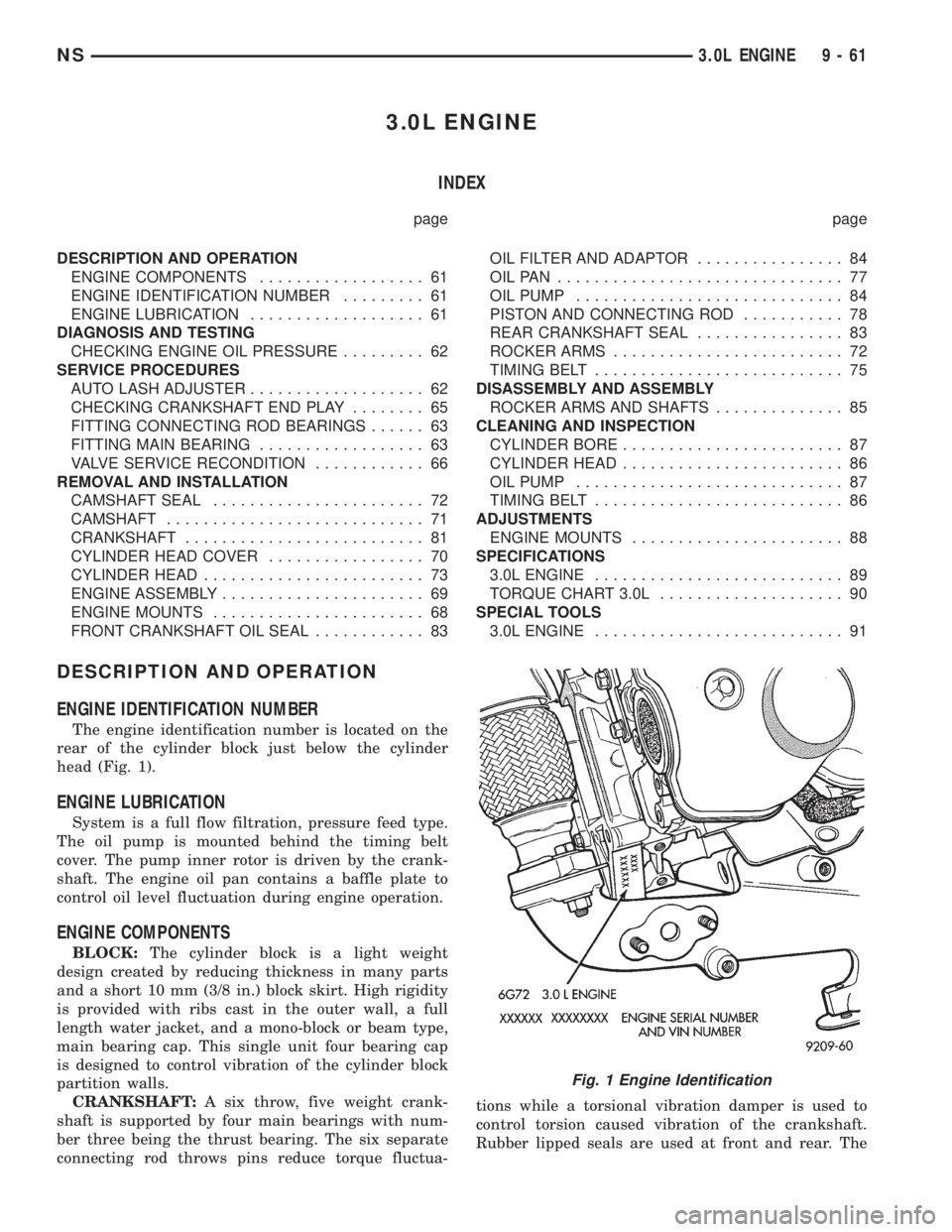
The engine identification number is located on the
rear of the cylinder block just below the cylinder
head (Fig. 1).
ENGINE LUBRICATION
System is a full flow filtration, pressure feed type.
The oil pump is mounted behind the timing belt
cover. The pump inner rotor is driven by the crank-
shaft. The engine oil pan contains a baffle plate to
control oil level fluctuation during engine operation.
ENGINE COMPONENTS
BLOCK:The cylinder block is a light weight
design created by reducing thickness in many parts
and a short 10 mm (3/8 in.) block skirt. High rigidity
is provided with ribs cast in the outer wall, a full
length water jacket, and a mono-block or beam type,
main bearing cap. This single unit four bearing cap
is designed to control vibration of the cylinder block
partition walls.
CRANKSHAFT:A six throw, five weight crank-
shaft is supported by four main bearings with num-
ber three being the thrust bearing. The six separate
connecting rod throws pins reduce torque fluctua-tions while a torsional vibration damper is used to
control torsion caused vibration of the crankshaft.
Rubber lipped seals are used at front and rear. The
Fig. 1 Engine Identification
NS3.0L ENGINE 9 - 61
Page 1112 of 1938
front seal is retained in the oil pump case and the
rear is retained in a block-mounted housing.
PISTONS:Are aluminum alloy with a steel strut,
short height, and thin wall so as to be autothermic
and light weight. The piston head with valve
recesses, in combination with the cylinder head,
forms a compact spherical head with clearance for
total valve lift with pistons at top dead center. The
piston skirt, top and second ring lands are finished to
a tapered roughness for oil retention and high resis-
tance to scuffing. Piston pins, pressed into place, join
the pistons to the connecting rods.
CYLINDER HEAD:The alloy cylinder heads fea-
ture cross-flow type intake and exhaust ports. Valve
guides and inserts are hardened cast iron. Valves of
heat resistance steel are arranged in a V with each
camshaft on center. To improve combustion speed the
chambers are a compact spherical design with a
squish area of approximately 30 percent of the piston
top area. The cylinder heads are common to either
cylinder bank by reversing the direction of installa-
tion.
CAMSHAFTS:Two overhead camshafts provide
valve actuation, one front (radiator side of cylinder
bank) and one rear. The front camshaft is provided
with a distributor drive and is longer. Both cam-
shafts are supported by four bearing journals, thrust
for the front camshaft is taken at journal two and
the rear at journal three. Front and rear camshaft
driving sprockets are interchangeable. The sprockets
and the engine water pump are driven by a single
notched timing belt.
ROCKER ARM SHAFTS:The shafts are retained
by the camshaft bearing journal caps. Four shafts are
used, one for each intake and exhaust rocker arm
assembly on each cylinder head. The hollow shafts
provide a duct for lubricating oil flow from the cylin-
der head to the valve mechanisms.
ROCKER ARMS:Are of light weight die-cast with
roller type follower operating against the cam shaft.
The valve actuating end of the rocker arms are
machined to retain hydraulic lash adjusters, elimi-
nating valve lash adjustment.
VALVES:Are made of heat resistant steel, valve
springs are especially designed to be short. The valve
spring wire cross-section is oval shaped and provides
the same spring tension as longer springs. Valve
spring retainers, locks and seals are conventional.
INTAKE MANIFOLD:The aluminum alloy mani-
fold is a cross type with long runners to improve
inertia. The runners, attaching below at the cylinder
head, also attach above and support an air plenum.
The air plenum chamber absorbs air pulsations cre-
ated during the suction phase of each cylinder.
EXHAUST MANIFOLDS:Both manifolds are a
log style made of ductile cast iron. Exhaust gasses,collected from the front cylinder bank, leave the front
manifold through an end outlet and are fed through
an upper crossover tube to the rear manifold. The
collected exhaust from both manifolds are combined,
and exit to the exhaust pipe through an articulated
joint.
DIAGNOSIS AND TESTING
CHECKING ENGINE OIL PRESSURE
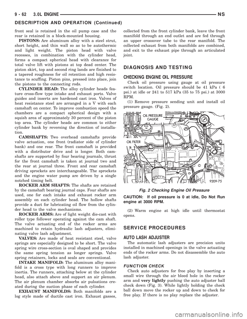
Check oil pressure using gauge at oil pressure
switch location. Oil pressure should be 41 kPa ( 6
psi.) at idle or 241 to 517 kPa (35 to 75 psi.) at 3000
RPM.
(1) Remove pressure sending unit and install oil
pressure gauge. (Fig. 2).
CAUTION: If oil pressure is 0 at idle, Do Not Run
engine at 3000 RPM.
(2) Warm engine at high idle until thermostat
opens.
SERVICE PROCEDURES
AUTO LASH ADJUSTER
The automatic lash adjusters are precision units
installed in machined openings in the valve actuating
ends of the rocker arms. Do not disassemble the auto
lash adjuster.
FUNCTION CHECK
Check auto adjusters for free play by inserting a
small wire through the air bleed hole in the rocker
arm andvery lightlypushing the auto adjuster ball
check down (Fig. 3). While lightly holding the check
ball down move the rocker up and down to check for
free play. If there is no play replace the adjuster.
Fig. 2 Checking Engine Oil Pressure
9 - 62 3.0L ENGINENS
DESCRIPTION AND OPERATION (Continued)
Page 1139 of 1938
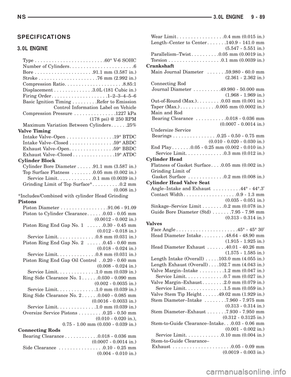
SPECIFICATIONS
3.0L ENGINE
Type.........................60É V-6 SOHC
Number of Cylinders.......................6
Bore.....................91.1 mm (3.587 in.)
Stroke.....................76mm(2.992 in.)
Compression Ratio.....................8.85:1
Displacement..............3.0L (181 Cubic in.)
Firing Order....................1±2±3±4±5±6
Basic Ignition Timing.........Refer to Emission
Control Information Label on Vehicle
Compression Pressure...............1227 kPa
(178 psi) @ 250 RPM
Maximum Variation Between Cylinders......25%
Valve Timing
Intake Valve±Open.................19É BTDC
Intake Valve±Closed................59É ABDC
Exhaust Valve±Open................59É BBDC
Exhaust Valve±Closed...............19É ATDC
Cylinder Block
Cylinder Bore Diameter......91.1 mm (3.587 in.)
Top Surface Flatness........0.05 mm (0.002 in.)
Service Limit.............0.1 mm (0.0039 in.)
Grinding Limit of Top Surface*..........0.2 mm
(0.008 in.)
*Includes/Combined with cylinder Head Grinding
Pistons
Piston Diameter.................91.06 - 91.09
Piston to Cylinder Clearance......0.03 - 0.05 mm
(0.0012 - 0.002 in.)
Piston Ring End Gap No. 1......0.30 - 0.45 mm
(0.012 - 0.018 in.)
Service Limit..............0.8 mm (0.031 in.)
Piston Ring End Gap No. 2......0.45 - 0.60 mm
(0.018 - 0.024 in.)
Service Limit..............0.8 mm (0.031 in.)
Piston Ring End Gap Oil Control . .0.20 - 0.60 mm
(0.008 - 0.024 in.)
Service Limit..............1.0 mm (0.039 in.)
Ring Side Clearance No. 1......0.030 - 0.090 mm
(0.002 - 0.0035 in.)
Service Limit..............1.0 mm (0.039 in.)
Ring Side Clearance No. 2......0.040 - 0.085 mm
(0.0016 - 0.0033 in.)
Service Limit..............1.0 mm (0.039 in.)
Oversize Service Pistons.........0.25 - 0.50 mm
(0.010 - 0.020 in.),
0.75 - 1.00 mm (0.030 - 0.039 in.)
Connecting Rods
Bearing Clearance............0.018 - 0.036 mm
(0.0007 - 0.0014 in.)
Side Clearance................0.10 - 0.25 mm
(0.004 - 0.010 in.)Wear Limit.................0.4 mm (0.015 in.)
Length±Center to Center.......140.9 - 141.0 mm
(5.547 - 5.551 in.)
Parallelism±Twist..........0.05 mm (0.0019 in.)
Torsion...................0.1 mm (0.0039 in.)
Crankshaft
Main Journal Diameter.......59.980 - 60.0 mm
(2.361 - 2.362 in.)
Connecting Rod
Journal Diameter..........49.980 - 50.000 mm
(1.968 - 1.969 in.)
Out-of-Round (Max.).........0.03 mm (0.001 in.)
Taper (Max.).............0.005 mm (0.0002 in.)
Main and Rod
Bearing Clearance...........0.018 - 0.036 mm
(0.0007 - 0.0014 in.)
Undersize Service
Bearings................0.25 - 0.50 - 0.75 mm
(0.010 - 0.020 - 0.030 in.)
End Play.......0.05 - 0.25 mm (0.002 - 0.010 in.)
Service Limit..............0.3 mm (0.012 in.)
Cylinder Head
Flatness of Gasket Surface. . . .0.05 mm (0.002 in.)
Grinding Limit of
Gasket Surface.............0.2 mm (0.008 in.)
Cylinder Head Valve Seat
Angle±Intake and Exhaust..........44É - 44É.3'
Contact Width...................0.9 - 1.3 mm
(0.035 - 0.051 in.)
Sinkage±Service Limit........0.2 mm (0.078 in.)
Guide Bore Diameter (Std).......7.95 - 7.98 mm
(0.313 - 0.314 in.)
Valves
Face Angle......................45É - 45É 30'
Head Diameter Intake.........48.64 - 48.90 mm
(1.915 - 1.925 in.)
Head Diameter Exhaust.......40.01 - 40.26 mm
(1.575 - 1.585 in.)
Length Intake (Overall).....103.0 mm (4.055 in.)
Length Exhaust (Overall). . . .102.7 mm (4.043 in.)
Valve Margin±Intake.........1.2 mm (0.047 in.)
Service Limit..............0.7 mm (0.027 in.)
Valve Margin±Exhaust........2.0 mm (0.079 in.)
Service Limit..............1.5 mm (0.059 in.)
Valve Stem Tip Height......49.02 mm (1.929 in.)
Stem Diameter±Intake........7.960 - 7.975 mm
(0.313 - 0.314 in.)
Stem Diameter±Exhaust.......7.930 - 7.950 mm
(0.312 - 0.3125 in.)
Stem-to-Guide Clearance±Intake . . .0.03 - 0.06 mm
(0.001 - 0.002 in.)
Service Limit.............0.10 mm (0.004 in.)
Stem-to-Guide Clearance±
Exhaust.....................0.05 - 0.09 mm
(0.0019 - 0.003 in.)
NS3.0L ENGINE 9 - 89
Page 1140 of 1938
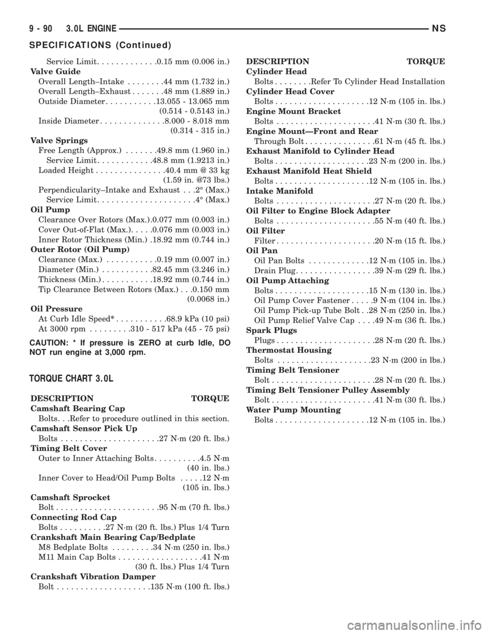
Service Limit.............0.15 mm (0.006 in.)
Valve Guide
Overall Length±Intake........44mm(1.732 in.)
Overall Length±Exhaust.......48mm(1.889 in.)
Outside Diameter...........13.055 - 13.065 mm
(0.514 - 0.5143 in.)
Inside Diameter..............8.000 - 8.018 mm
(0.314 - 315 in.)
Valve Springs
Free Length (Approx.).......49.8 mm (1.960 in.)
Service Limit............48.8 mm (1.9213 in.)
Loaded Height...............40.4 mm @ 33 kg
(1.59 in. @73 lbs.)
Perpendicularity±Intake and Exhaust . . .2É (Max.)
Service Limit.....................4É(Max.)
Oil Pump
Clearance Over Rotors (Max.) .0.077 mm (0.003 in.)
Cover Out-of-Flat (Max.).....0.076 mm (0.003 in.)
Inner Rotor Thickness (Min.) .18.92 mm (0.744 in.)
Outer Rotor (Oil Pump)
Clearance (Max.)...........0.19 mm (0.007 in.)
Diameter (Min.)...........82.45 mm (3.246 in.)
Thickness (Min.)...........18.92 mm (0.744 in.)
Tip Clearance Between Rotors (Max.) . . .0.150 mm
(0.0068 in.)
Oil Pressure
At Curb Idle Speed*...........68.9 kPa (10 psi)
At 3000 rpm.........310 - 517 kPa (45 - 75 psi)
CAUTION: * If pressure is ZERO at curb Idle, DO
NOT run engine at 3,000 rpm.
TORQUE CHART 3.0L
DESCRIPTION TORQUE
Camshaft Bearing Cap
Bolts. . .Refer to procedure outlined in this section.
Camshaft Sensor Pick Up
Bolts.....................27N´m(20ft.lbs.)
Timing Belt Cover
Outer to Inner Attaching Bolts..........4.5 N´m
(40 in. lbs.)
Inner Cover to Head/Oil Pump Bolts.....12N´m
(105 in. lbs.)
Camshaft Sprocket
Bolt......................95N´m(70ft.lbs.)
Connecting Rod Cap
Bolts..........27N´m(20ft.lbs.) Plus 1/4 Turn
Crankshaft Main Bearing Cap/Bedplate
M8 Bedplate Bolts.........34N´m(250 in. lbs.)
M11 Main Cap Bolts..................41N´m
(30 ft. lbs.) Plus 1/4 Turn
Crankshaft Vibration Damper
Bolt....................135 N´m (100 ft. lbs.)DESCRIPTION TORQUE
Cylinder Head
Bolts........Refer To Cylinder Head Installation
Cylinder Head Cover
Bolts....................12N´m(105 in. lbs.)
Engine Mount Bracket
Bolts.....................41N´m(30ft.lbs.)
Engine MountÐFront and Rear
Through Bolt...............61N´m(45ft.lbs.)
Exhaust Manifold to Cylinder Head
Bolts....................23N´m(200 in. lbs.)
Exhaust Manifold Heat Shield
Bolts....................12N´m(105 in. lbs.)
Intake Manifold
Bolts.....................27N´m(20ft.lbs.)
Oil Filter to Engine Block Adapter
Bolts.....................55N´m(40ft.lbs.)
Oil Filter
Filter.....................20N´m(15ft.lbs.)
Oil Pan
Oil Pan Bolts.............12N´m(105 in. lbs.)
Drain Plug.................39N´m(29ft.lbs.)
Oil Pump Attaching
Bolts....................15N´m(130 in. lbs.)
Oil Pump Cover Fastener.....9N´m(104 in. lbs.)
Oil Pump Pick-up Tube Bolt . .28 N´m (250 in. lbs.)
Oil Pump Relief Valve Cap. . . .49 N´m (36 ft. lbs.)
Spark Plugs
Plugs.....................28N´m(20ft.lbs.)
Thermostat Housing
Bolts....................23N´m(200 in lbs.)
Timing Belt Tensioner
Bolt......................28N´m(20ft.lbs.)
Timing Belt Tensioner Pulley Assembly
Bolt......................41N´m(30ft.lbs.)
Water Pump Mounting
Bolts....................12N´m(105 in. lbs.)
9 - 90 3.0L ENGINENS
SPECIFICATIONS (Continued)
Page 1143 of 1938
3.3/3.8L ENGINE
INDEX
page page
DESCRIPTION AND OPERATION
ENGINE COMPONENTS.................. 93
ENGINE IDENTIFICATION................. 93
ENGINE LUBRICATION SYSTEM............ 93
DIAGNOSIS AND TESTING
CHECKING ENGINE OIL PRESSURE......... 96
HYDRAULIC TAPPETS.................... 94
SERVICE PROCEDURES
CRANKSHAFT END PLAY................. 99
FITTING CONNECTING ROD BEARINGS...... 97
FITTING MAIN BEARINGS................. 98
FITTING PISTONS AND RINGS............. 97
MEASURING TIMING CHAIN FOR STRETCH . . . 96
VALVE SERVICE RECONDITION........... 100
VALVE TIMING.......................... 96
REMOVAL AND INSTALLATION
CAMSHAFT BEARINGS.................. 114
CAMSHAFT........................... 113
CRANKSHAFT DAMPER................. 106
CRANKSHAFT OIL SEALÐFRONT.......... 117
CRANKSHAFT OIL SEALÐREAR........... 118
CRANKSHAFT......................... 116
CYLINDER HEAD COVER................ 107
CYLINDER HEAD....................... 108
ENGINE ASSEMBLY..................... 104
ENGINE MOUNTS...................... 102
ENGINE OIL GALLERY PLUGS............. 119OILFILTER ............................ 119
OILPAN .............................. 114
PISTON AND CONNECTING ROD.......... 115
ROCKER ARMS AND SHAFT ASSEMBLY..... 106
TAPPET REMOVAL...................... 110
TIMING CHAIN COVER................... 111
TIMING CHAIN......................... 112
VALVE STEM SEALS OR SPRINGS,
CYLINDER HEAD NOT REMOVED........ 106
VALVES AND VALVE SPRINGS............ 109
WIPER UNIT.......................... 102
DISASSEMBLY AND ASSEMBLY
HYDRAULIC TAPPETS................... 120
OIL PUMP............................ 119
CLEANING AND INSPECTION
CYLINDER HEAD....................... 120
ENGINE BLOCK AND BORE............... 121
OILPAN .............................. 121
OIL PUMP............................ 121
ADJUSTMENTS
ENGINE MOUNTS...................... 123
SPECIFICATIONS
3.3/3.8L ENGINE....................... 123
TORQUE CHART....................... 125
SPECIAL TOOLS
3.3/3.8L ENGINE....................... 127
DESCRIPTION AND OPERATION
ENGINE IDENTIFICATION
The engine identification number is located on the
rear of the cylinder block just below the cylinder
head (Fig. 1).
ENGINE LUBRICATION SYSTEM
The lubrication system is a full flow filtration pres-
sure feed type. Oil from the oil pan is pumped by a
internal gear type oil pump directly coupled to the
crankshaft. The pressure is regulated by a relief
valve located in the chain case cover. The oil is
pumped through an oil filter and feeds a main oil
galley. This oil gallery feeds oil under pressure to the
main and rod bearings, camshaft bearings. Passages
in the cylinder block feed oil to the hydraulic lifters
and rocker shaft brackets which feeds the rocker arm
pivots (Fig. 2).
ENGINE COMPONENTS
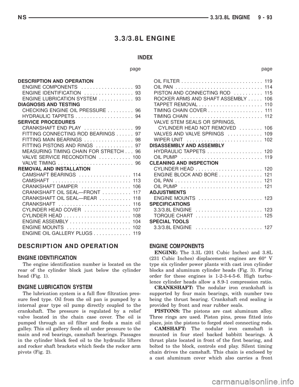
ENGINE:The 3.3L (201 Cubic Inches) and 3.8L
(231 Cubic Inches) displacement engines are 60É V
type six cylinder power plants with cast iron cylinder
blocks and aluminum cylinder heads (Fig. 3). Firing
order for these engines is 1-2-3-4-5-6. High turbu-
lence cylinder heads allow a 8.9-1 compression ratio.
CRANKSHAFT:The nodular iron crankshaft is
supported by four main bearings, with number two
being the thrust bearing. Crankshaft end sealing is
provided by front and rear rubber seals.
PISTONS:The pistons are cast aluminum alloy.
Three rings are used. Piston pins, press fitted into
place, join the pistons to forged steel connecting rods.
CAMSHAFT:The nodular iron camshaft is
mounted in four steel backed babbitt bearings. A
thrust plate located in front of the first bearing, and
bolted to the block, controls end play. Silent timing
chain drives the camshaft. This chain is enclosed by
a cast aluminum cover which also carries a front
NS3.3/3.8L ENGINE 9 - 93
Page 1145 of 1938
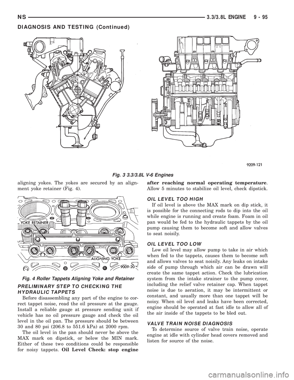
aligning yokes. The yokes are secured by an align-
ment yoke retainer (Fig. 4).
PRELIMINARY STEP TO CHECKING THE
HYDRAULIC TAPPETS
Before disassembling any part of the engine to cor-
rect tappet noise, read the oil pressure at the gauge.
Install a reliable gauge at pressure sending unit if
vehicle has no oil pressure gauge and check the oil
level in the oil pan. The pressure should be between
30 and 80 psi (206.8 to 551.6 kPa) at 2000 rpm.
The oil level in the pan should never be above the
MAX mark on dipstick, or below the MIN mark.
Either of these two conditions could be responsible
for noisy tappets.Oil Level Check: stop engineafter reaching normal operating temperature.
Allow 5 minutes to stabilize oil level, check dipstick.
OIL LEVEL TOO HIGH
If oil level is above the MAX mark on dip stick, it
is possible for the connecting rods to dip into the oil
while engine is running and create foam. Foam in oil
pan would be fed to the hydraulic tappets by the oil
pump causing them to become soft and allow valves
to seat noisily.
OIL LEVEL TOO LOW
Low oil level may allow pump to take in air which
when fed to the tappets, causes them to become soft
and allows valves to seat noisily. Any leaks on intake
side of pump through which air can be drawn will
create the same tappet action. Check the lubrication
system from the intake strainer to the pump cover,
including the relief valve retainer cap. When tappet
noise is due to aeration, it may be intermittent or
constant, and usually more than one tappet will be
noisy. When oil level and leaks have been corrected,
engine should be operated at fast idle to allow all of
the air inside of the tappets to be bled out.
VALVE TRAIN NOISE DIAGNOSIS
To determine source of valve train noise, operate
engine at idle with cylinder head covers removed and
listen for source of the noise.
Fig. 3 3.3/3.8L V-6 Engines
Fig. 4 Roller Tappets Aligning Yoke and Retainer
NS3.3/3.8L ENGINE 9 - 95
DIAGNOSIS AND TESTING (Continued)