1996 CHRYSLER VOYAGER oil pressure
[x] Cancel search: oil pressurePage 1238 of 1938
(36) Operate the engine with the radiator cap off.
Inspect for leaks and continue operating the engine
until the thermostat opens. Add coolant, if required.
VALVES AND VALVE SPRINGSÐHEAD OFF
This procedure is done with the engine cylinder
head removed from the block.
REMOVAL
(1) Remove the engine cylinder head from the cyl-
inder block. Refer to cylinder head removal in this
section.
(2) Use Valve Spring Compressor Tool and com-
press each valve spring.
(3) Remove the valve locks, retainers, and springs.
(4) Use an Arkansas smooth stone or a jewelers
file to remove any burrs on the top of the valve stem,
especially around the groove for the locks.
(5) Remove the valves, and place them in a rack in
the same order as removed.
INSTALLATION
(1) Fit each valve to its respective valve guide.
NOTE: If valves and valve seats have been refaced
refer to Service Procedures in this section. Follow
The Valve Stand Down procedure.
(2) Install lower, washer and spring.
(3) Install upper spring collar, and compress valve
spring with spring compressor tool. Install split cone
retainers.
HYDRAULIC TAPPETS
REMOVAL
(1) Remove coolant pressure bottle.
(2) Remove cylinder head cover. Refer to cylinder
head cover removal in this section.
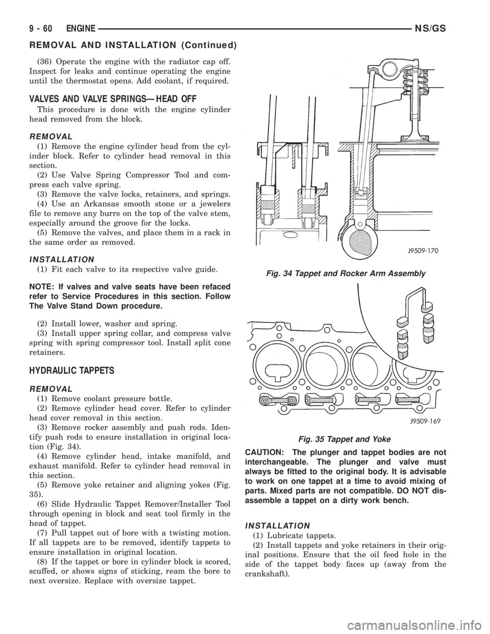
(3) Remove rocker assembly and push rods. Iden-
tify push rods to ensure installation in original loca-
tion (Fig. 34).
(4) Remove cylinder head, intake manifold, and
exhaust manifold. Refer to cylinder head removal in
this section.
(5) Remove yoke retainer and aligning yokes (Fig.
35).
(6) Slide Hydraulic Tappet Remover/Installer Tool
through opening in block and seat tool firmly in the
head of tappet.
(7) Pull tappet out of bore with a twisting motion.
If all tappets are to be removed, identify tappets to
ensure installation in original location.
(8) If the tappet or bore in cylinder block is scored,
scuffed, or shows signs of sticking, ream the bore to
next oversize. Replace with oversize tappet.CAUTION: The plunger and tappet bodies are not
interchangeable. The plunger and valve must
always be fitted to the original body. It is advisable
to work on one tappet at a time to avoid mixing of
parts. Mixed parts are not compatible. DO NOT dis-
assemble a tappet on a dirty work bench.
INSTALLATION
(1) Lubricate tappets.
(2) Install tappets and yoke retainers in their orig-
inal positions. Ensure that the oil feed hole in the
side of the tappet body faces up (away from the
crankshaft).
Fig. 34 Tappet and Rocker Arm Assembly
Fig. 35 Tappet and Yoke
9 - 60 ENGINENS/GS
REMOVAL AND INSTALLATION (Continued)
Page 1245 of 1938
(3) Drain oil.
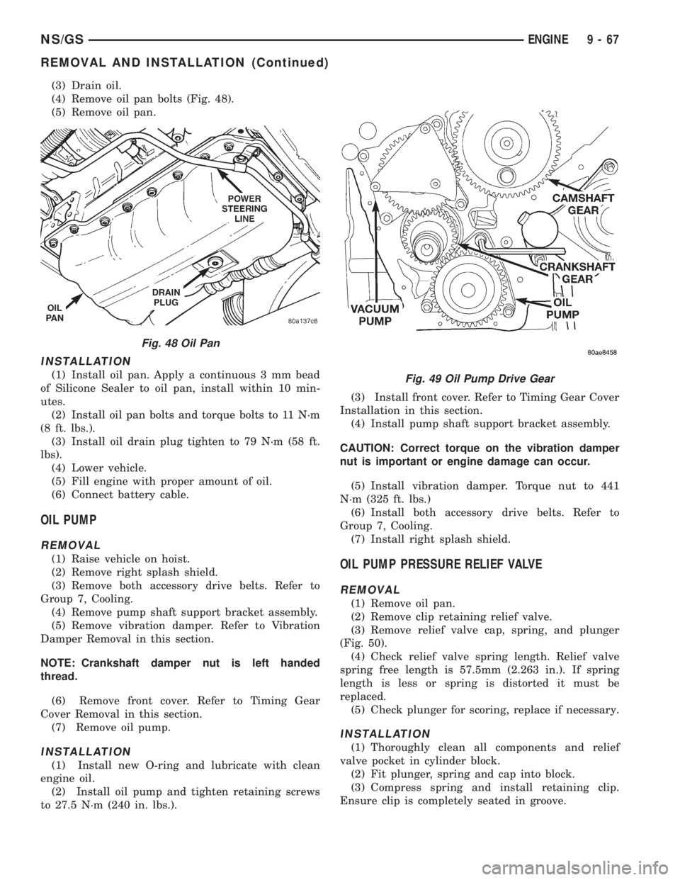
(4) Remove oil pan bolts (Fig. 48).
(5) Remove oil pan.
INSTALLATION
(1) Install oil pan. Apply a continuous 3 mm bead
of Silicone Sealer to oil pan, install within 10 min-
utes.
(2) Install oil pan bolts and torque bolts to 11 N´m
(8 ft. lbs.).
(3) Install oil drain plug tighten to 79 N´m (58 ft.
lbs).
(4) Lower vehicle.
(5) Fill engine with proper amount of oil.
(6) Connect battery cable.
OIL PUMP
REMOVAL
(1) Raise vehicle on hoist.
(2) Remove right splash shield.
(3) Remove both accessory drive belts. Refer to
Group 7, Cooling.
(4) Remove pump shaft support bracket assembly.
(5) Remove vibration damper. Refer to Vibration
Damper Removal in this section.
NOTE: Crankshaft damper nut is left handed
thread.
(6) Remove front cover. Refer to Timing Gear
Cover Removal in this section.
(7) Remove oil pump.
INSTALLATION
(1) Install new O-ring and lubricate with clean
engine oil.
(2) Install oil pump and tighten retaining screws
to 27.5 N´m (240 in. lbs.).(3) Install front cover. Refer to Timing Gear Cover
Installation in this section.
(4) Install pump shaft support bracket assembly.
CAUTION: Correct torque on the vibration damper
nut is important or engine damage can occur.
(5) Install vibration damper. Torque nut to 441
N´m (325 ft. lbs.)
(6) Install both accessory drive belts. Refer to
Group 7, Cooling.
(7) Install right splash shield.
OIL PUMP PRESSURE RELIEF VALVE
REMOVAL
(1) Remove oil pan.
(2) Remove clip retaining relief valve.
(3) Remove relief valve cap, spring, and plunger
(Fig. 50).
(4) Check relief valve spring length. Relief valve
spring free length is 57.5mm (2.263 in.). If spring
length is less or spring is distorted it must be
replaced.
(5) Check plunger for scoring, replace if necessary.
INSTALLATION
(1) Thoroughly clean all components and relief
valve pocket in cylinder block.
(2) Fit plunger, spring and cap into block.
(3) Compress spring and install retaining clip.
Ensure clip is completely seated in groove.
Fig. 48 Oil Pan
Fig. 49 Oil Pump Drive Gear
NS/GSENGINE 9 - 67
REMOVAL AND INSTALLATION (Continued)
Page 1246 of 1938
OIL FILTER ADAPTER AND OIL COOLER
REMOVAL
(1) Remove oil filter.
(2) Remove oil cooler adapter bolt.
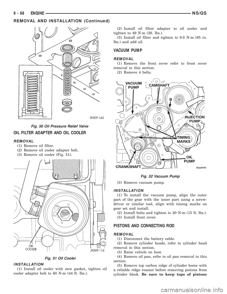
(3) Remove oil cooler (Fig. 51).
INSTALLATION
(1) Install oil cooler with new gasket, tighten oil
cooler adapter bolt to 60 N´m (44 ft. lbs.).(2) Install oil filter adapter to oil cooler and
tighten to 49 N´m (36. lbs.).
(3) Install oil filter and tighten to 9.8 N´m (85 in.
lbs.) and add oil.
VACUUM PUMP
REMOVAL
(1) Remove the front cover refer to front cover
removal in this section.
(2) Remove 4 bolts.
(3) Remove vacuum pump.
INSTALLATION
(1) To install the vacuum pump, align the outer
part of the gear with the inner part using a screw-
driver or similar tool, align with timing marks on
gear set and install.
(2) Install bolts and tighten to 20 N´m (15 ft. lbs.).
(3) Install front cover.
PISTONS AND CONNECTING ROD
REMOVAL
(1) Disconnect the battery cable.
(2) Remove cylinder heads, refer to cylinder head
removal in this section.
(3) Raise vehicle on host.
(4) Remove oil pan, refer to oil pan removal in this
section.
(5) Remove top carbon ridge of cylinder bores with
a reliable ridge reamer before removing pistons from
cylinder block.Be sure to keep tops of pistons
Fig. 50 Oil Pressure Relief Valve
Fig. 51 Oil Cooler
Fig. 52 Vacuum Pump
9 - 68 ENGINENS/GS
REMOVAL AND INSTALLATION (Continued)
Page 1258 of 1938
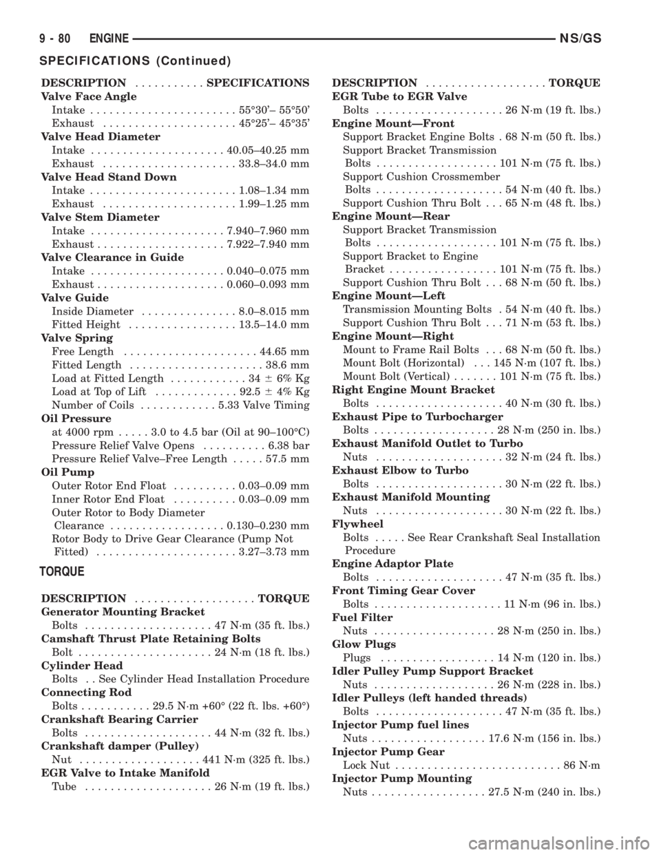
DESCRIPTION...........SPECIFICATIONS
Valve Face Angle
Intake.......................55É30'± 55É50'
Exhaust.....................45É25'± 45É35'
Valve Head Diameter
Intake.....................40.05±40.25 mm
Exhaust.....................33.8±34.0 mm
Valve Head Stand Down
Intake.......................1.08±1.34 mm
Exhaust.....................1.99±1.25 mm
Valve Stem Diameter
Intake.....................7.940±7.960 mm
Exhaust....................7.922±7.940 mm
Valve Clearance in Guide
Intake.....................0.040±0.075 mm
Exhaust....................0.060±0.093 mm
Valve Guide
Inside Diameter...............8.0±8.015 mm
Fitted Height.................13.5±14.0 mm
Valve Spring
Free Length.....................44.65 mm
Fitted Length.....................38.6 mm
Load at Fitted Length............3466% Kg
Load at Top of Lift.............92.564% Kg
Number of Coils............5.33 Valve Timing
Oil Pressure
at 4000 rpm.....3.0to4.5bar(Oil at 90±100ÉC)
Pressure Relief Valve Opens..........6.38 bar
Pressure Relief Valve±Free Length.....57.5 mm
Oil Pump
Outer Rotor End Float..........0.03±0.09 mm
Inner Rotor End Float..........0.03±0.09 mm
Outer Rotor to Body Diameter
Clearance..................0.130±0.230 mm
Rotor Body to Drive Gear Clearance (Pump Not
Fitted)......................3.27±3.73 mm
TORQUE
DESCRIPTION...................TORQUE
Generator Mounting Bracket
Bolts....................47N´m(35ft.lbs.)
Camshaft Thrust Plate Retaining Bolts
Bolt.....................24N´m(18ft.lbs.)
Cylinder Head
Bolts . . See Cylinder Head Installation Procedure
Connecting Rod
Bolts...........29.5 N´m +60É (22 ft. lbs. +60É)
Crankshaft Bearing Carrier
Bolts....................44N´m(32ft.lbs.)
Crankshaft damper (Pulley)
Nut ...................441N´m(325 ft. lbs.)
EGR Valve to Intake Manifold
Tube ....................26N´m(19ft.lbs.)DESCRIPTION...................TORQUE
EGR Tube to EGR Valve
Bolts....................26N´m(19ft.lbs.)
Engine MountÐFront
Support Bracket Engine Bolts . 68 N´m (50 ft. lbs.)
Support Bracket Transmission
Bolts...................101N´m(75ft.lbs.)
Support Cushion Crossmember
Bolts....................54N´m(40ft.lbs.)
Support Cushion Thru Bolt . . . 65 N´m (48 ft. lbs.)
Engine MountÐRear
Support Bracket Transmission
Bolts...................101N´m(75ft.lbs.)
Support Bracket to Engine
Bracket.................101N´m(75ft.lbs.)
Support Cushion Thru Bolt . . . 68 N´m (50 ft. lbs.)
Engine MountÐLeft
Transmission Mounting Bolts . 54 N´m (40 ft. lbs.)
Support Cushion Thru Bolt . . . 71 N´m (53 ft. lbs.)
Engine MountÐRight
Mount to Frame Rail Bolts . . . 68 N´m (50 ft. lbs.)
Mount Bolt (Horizontal) . . . 145 N´m (107 ft. lbs.)
Mount Bolt (Vertical).......101N´m(75ft.lbs.)
Right Engine Mount Bracket
Bolts....................40N´m(30ft.lbs.)
Exhaust Pipe to Turbocharger
Bolts...................28N´m(250 in. lbs.)
Exhaust Manifold Outlet to Turbo
Nuts....................32N´m(24ft.lbs.)
Exhaust Elbow to Turbo
Bolts....................30N´m(22ft.lbs.)
Exhaust Manifold Mounting
Nuts....................30N´m(22ft.lbs.)
Flywheel
Bolts.....SeeRear Crankshaft Seal Installation
Procedure
Engine Adaptor Plate
Bolts....................47N´m(35ft.lbs.)
Front Timing Gear Cover
Bolts....................11N´m(96in.lbs.)
Fuel Filter
Nuts...................28N´m(250 in. lbs.)
Glow Plugs
Plugs..................14N´m(120 in. lbs.)
Idler Pulley Pump Support Bracket
Nuts...................26N´m(228 in. lbs.)
Idler Pulleys (left handed threads)
Bolts....................47N´m(35ft.lbs.)
Injector Pump fuel lines
Nuts..................17.6 N´m (156 in. lbs.)
Injector Pump Gear
Lock Nut..........................86N´m
Injector Pump Mounting
Nuts..................27.5 N´m (240 in. lbs.)
9 - 80 ENGINENS/GS
SPECIFICATIONS (Continued)
Page 1259 of 1938
DESCRIPTION...................TORQUE
Injector
Tighten to................65N´m(48ft.lbs.)
Intake Manifold Mounting
Nuts...................30N´m(264 in. lbs.)
Main Bearing Oil Delivery Union
Bolts....................54N´m(40ft.lbs.)
Oil Feed Line To Rocker Arms
Bolts.................12.7 N´m (108 in. lbs.)
Oil Feed Line to Block
Bolts.................12.7 N´m (108 in. lbs.)
Oil Feel Line to Vacuum Pump
Bolts.................16.7 N´m (145 in. lbs.)
Oil Filter
Tighten to...............9.8N´m(85in.lbs.)
Oil Filter Adaptor
Fastener.................49N´m(36ft.lbs.)
Oil Filter Base
Fastener.................49N´m(36ft.lbs.)
Oil Pan Mounting
Bolts...................12N´m(108 in. lbs.)
Oil Pickup Tube
Bolts..................11.3N´m(100 in. lbs.)
Oil Pump Mounting
Bolts.................27.5 N´m (240 in. lbs.)
Oil Pan Drain
Plug.....................54N´m(40ft.lbs.)
Power Steering Pressure Hose
Fastener................28N´m(240 in. lbs.)
Power Steering Pulley
Nut ...................170N´m(125 ft. lbs.)
Rear Crankshaft Bearing Carrier
Bolts..................10.8 N´m (95 in. lbs.)
Rocker Arm Cover
Bolts.................14.7 N´m (132 in. lbs.)
Rocker Arm Mounting
Nuts..................29.4 N´m (264 in. lbs.)
Power Steering Pump Mounting
Nuts..................24.5 N´m (216 in. lbs.)
Turbocharger Mounting
Nuts...................32N´m(288 in. lbs.)
Turbocharger Oil Delivery
Bolt..................27.5 N´m (240 in. lbs.)
Turbocharger Oil Drain
Bolts..................10.8 N´m (95 in. lbs.)
Vacuum Pump Mounting
Bolts..................10.8 N´m (95 in. lbs.)
Water Manifold Mounting
Bolts..................11.8N´m(108 in. lbs.)
Water Pump Pulley
Bolts.................27.5 N´m (240 in. lbs.)SPECIAL TOOLS
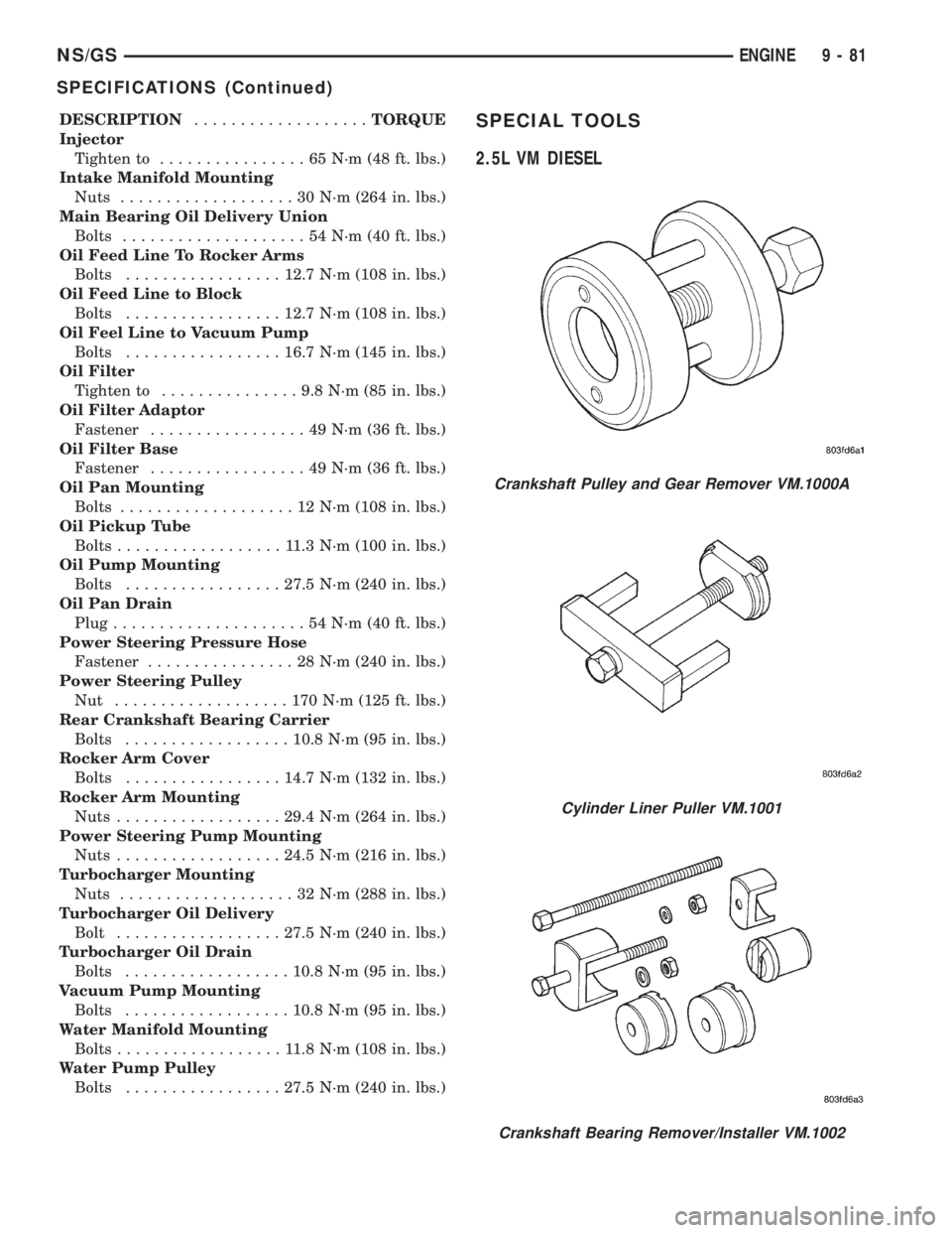
2.5L VM DIESEL
Crankshaft Pulley and Gear Remover VM.1000A
Cylinder Liner Puller VM.1001
Crankshaft Bearing Remover/Installer VM.1002
NS/GSENGINE 9 - 81
SPECIFICATIONS (Continued)
Page 1266 of 1938
REMOVAL AND INSTALLATION
EXHAUST PIPES, MUFFLERS AND TAILPIPES
REMOVAL
(1) Raise vehicle on hoist and apply penetrating
oil to clamp bolts and nuts of component being
removed.
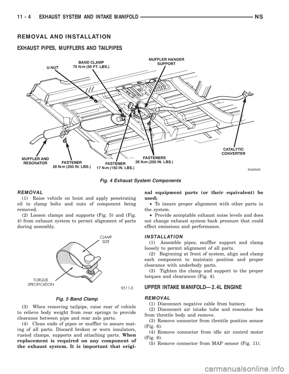
(2) Loosen clamps and supports (Fig. 5) and (Fig.
4) from exhaust system to permit alignment of parts
during assembly.
(3) When removing tailpipe, raise rear of vehicle
to relieve body weight from rear springs to provide
clearance between pipe and rear axle parts.
(4) Clean ends of pipes or muffler to assure mat-
ing of all parts. Discard broken or worn insulators,
rusted clamps, supports and attaching parts.When
replacement is required on any component of
the exhaust system. It is important that origi-nal equipment parts (or their equivalent) be
used;
²To insure proper alignment with other parts in
the system.
²Provide acceptable exhaust noise levels and does
not change exhaust system back pressure that could
effect emissions and performance.
INSTALLATION
(1) Assemble pipes, muffler support and clamp
loosely to permit alignment of all parts.
(2) Beginning at front of system, align and clamp
each component to maintain position and proper
clearance with underbody parts.
(3) Tighten the clamp and support to the proper
torques and clearances (Fig. 4).
UPPER INTAKE MANIFOLDÐ2.4L ENGINE
REMOVAL
(1) Disconnect negative cable from battery.
(2) Disconnect air intake tube and resonator box
from throttle body and remove.
(3) Remove connector from throttle position sensor
(Fig. 6).
(4) Remove connector from idle air control motor
(Fig. 6).
(5) Remove connector from MAP sensor (Fig. 11).
Fig. 4 Exhaust System Components
Fig. 5 Band Clamp
11 - 4 EXHAUST SYSTEM AND INTAKE MANIFOLDNS
Page 1270 of 1938
(2) Tighten intake manifold fasteners in the fol-
lowing sequence (Fig. 16). Torque to 23 N´m (200 in.
lbs.). Repeat this procedure until all bolts are at
specified torque.
(3) Install intake manifold center support bracket
bolts (Y bracket):
²Fastener to block 54 N´m (40 ft. lbs.)
²Fastener to intake 28 N´m (250 in. lbs.)
(4) Install fuel hose quick connector fitting to
chassis tubes.Refer to Fuel Hoses, Clamps and
Quick Connect Fittings in Group 14, Fuel Deliv-
ery.Push the fitting onto the chassis tube until it
clicks into place. Pull on the fitting to ensure com-
plete insertion.
(5) Reverse removal procedures 2 through 12 for
installation.
CAUTION: When using the ASD Fuel System Test,
the ASD relay and fuel pump relay remain energized
for 7 minutes or until the test is stopped, or until
the ignition switch is turned to the Off position.
(6) With the ignition key in ON position, access
the DRB scan tool ASD Fuel System Test to pressur-
ize the fuel system. Check for leaks.
EXHAUST MANIFOLDÐ2.4L ENGINE
REMOVAL
(1) Raise vehicle and disconnect exhaust pipe from
the exhaust manifold at the flex-joint.
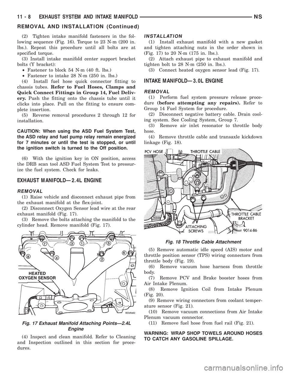
(2) Disconnect Oxygen Sensor lead wire at the rear
exhaust manifold (Fig. 17).
(3) Remove the bolts attaching the manifold to the
cylinder head. Remove manifold (Fig. 17).
(4) Inspect and clean manifold. Refer to Cleaning
and Inspection outlined in this section for proce-
dures.
INSTALLATION
(1) Install exhaust manifold with a new gasket
and tighten attaching nuts in the order shown in
(Fig. 17) to 20 N´m (175 in. lbs.).
(2) Attach exhaust pipe to exhaust manifold and
tighten bolt to 28 N´m (250 in. lbs.).
(3) Connect heated oxygen sensor lead (Fig. 17).
INTAKE MANIFOLDÐ3.0L ENGINE
REMOVAL
(1) Perform fuel system pressure release proce-
dure(before attempting any repairs).Refer to
Group 14 Fuel System for procedure.
(2) Disconnect negative battery cable. Drain cool-
ing system. See Cooling System, Group 7.
(3) Remove air inlet resonator to throttle body
hose.
(4) Remove throttle cable and transaxle kickdown
linkage (Fig. 18).
(5) Remove automatic idle speed (AIS) motor and
throttle position sensor (TPS) wiring connectors from
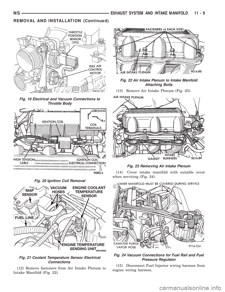
throttle body (Fig. 19).
(6) Remove vacuum hose harness from throttle
body.
(7) Remove PCV and Brake booster hoses from
Air Intake Plenum.
(8) Remove Ignition Coil from Intake Plenum
(Fig. 20).
(9) Remove wiring connectors from coolant temper-
ature sensor (Fig. 21).
(10) Remove vacuum connections from Air Intake
Plenum vacuum connector.
(11) Remove fuel hose from fuel rail (Fig. 21).
WARNING: WRAP SHOP TOWELS AROUND HOSES
TO CATCH ANY GASOLINE SPILLAGE.
Fig. 17 Exhaust Manifold Attaching PointsÐ2.4L
Engine
Fig. 18 Throttle Cable Attachment
11 - 8 EXHAUST SYSTEM AND INTAKE MANIFOLDNS
REMOVAL AND INSTALLATION (Continued)
Page 1271 of 1938
(12) Remove fasteners from Air Intake Plenum to
Intake Manifold (Fig. 22).(13) Remove Air Intake Plenum (Fig. 23).
(14) Cover intake manifold with suitable cover
when servicing (Fig. 24).
(15) Disconnect Fuel Injector wiring harness from
engine wiring harness.
Fig. 19 Electrical and Vacuum Connections to
Throttle Body
Fig. 20 Ignition Coil Removal
Fig. 21 Coolant Temperature Sensor Electrical
Connections
Fig. 22 Air Intake Plenum to Intake Manifold
Attaching Bolts
Fig. 23 Removing Air Intake Plenum
Fig. 24 Vacuum Connections for Fuel Rail and Fuel
Pressure Regulator
NSEXHAUST SYSTEM AND INTAKE MANIFOLD 11 - 9
REMOVAL AND INSTALLATION (Continued)