1996 CHRYSLER VOYAGER oil pressure
[x] Cancel search: oil pressurePage 1411 of 1938
FUEL INJECTION SYSTEMÐ2.5L DIESEL ENGINE
INDEX
page page
GENERAL INFORMATION
INTRODUCTION....................... 43
DESCRIPTION AND OPERATION
AIR CONDITIONING (A/C) CONTROLSÐ
PCM INPUTS........................ 47
AIR CONDITIONING RELAYÐPCM OUTPUT . . 48
BATTERY VOLTAGEÐPCM INPUT.......... 45
BOOST PRESSURE SENSOR............. 45
BRAKE SWITCHÐPCM INPUT............. 47
DATA LINK CONNECTORÐ
PCM INPUT AND OUTPUT.............. 47
DIESEL PCM RELAYÐPCM INPUT......... 48
ENGINE COOLANT GAUGEÐPCM OUTPUT . . 48
ENGINE COOLANT TEMPERATURE SENSORÐ
PCM INPUT......................... 46
ENGINE OIL PRESSURE GAUGEÐ
PCM OUTPUT........................ 48
ENGINE SPEED SENSORÐPCM INPUT..... 46
EXHAUST GAS RECIRCULATION (EGR)
SOLENOIDÐPCM OUTPUT............. 50
FIVE VOLT POWERÐPCM OUTPUT........ 48
FUEL INJECTOR SENSORÐGROUND...... 46
FUEL TIMING SOLENOIDÐPCM OUTPUT.... 48
GLOW PLUG LAMPÐPCM OUTPUT........ 48
GLOW PLUG RELAYÐPCM OUTPUT....... 49
GLOW PLUGS......................... 49
IGNITION CIRCUIT SENSEÐPCM INPUT.... 45
NEEDLE MOVEMENT OR INSTRUMENTED
FIRST INJECTORÐPCM INPUT.......... 45
POWER GROUND...................... 45
POWERTRAIN CONTROL MODULE (PCM) . . . 44
SENSOR RETURNÐPCM INPUT (ANALOG
GROUND)........................... 45SIGNAL GROUNDÐPCM INPUT........... 45
SPEED CONTROLÐPCM INPUTS.......... 48
SPEED CONTROLÐPCM OUTPUTS........ 48
START SIGNALÐPCM INPUT............. 45
TACHOMETERÐPCM OUTPUT............ 49
VEHICLE SPEED SENSORÐPCM INPUT.... 47
VEHICLE THEFT ALARM................. 45
DIAGNOSIS AND TESTING
BOOST PRESSURE SENSOR............. 53
DIAGNOSTIC TROUBLE CODES........... 53
DIESEL DIAGNOSTICS.................. 50
DIESEL PCM RELAY TEST............... 50
ENGINE COOLANT TEMPERATURE
SENSOR TEST....................... 50
ENGINE SPEED SENSOR TEST........... 50
GLOW PLUG RELAY TEST............... 51
GLOW PLUG TEST..................... 51
RELAYSÐOPERATION/TESTING........... 52
VEHICLE SPEED SENSOR TEST........... 53
REMOVAL AND INSTALLATION
A/C CLUTCH RELAY.................... 53
DIESEL PCM RELAY.................... 53
ENGINE COOLANT TEMPERATURE
SENSOR............................ 54
ENGINE SPEED SENSOR................ 53
GLOW PLUG RELAY.................... 55
GLOW PLUGS......................... 54
POWERTRAIN CONTROL MODULE (PCM) . . . 55
VEHICLE SPEED SENSOR............... 55
SPECIFICATIONS
GLOW PLUG CURRENT DRAW............ 56
TORQUE CHARTÐ2.5L DIESEL............ 57
GENERAL INFORMATION
INTRODUCTION
This section will cover components either regulated
or controlled by the Powertrain Control Module
(PCM). The fuel heater relay, fuel heater and fuel
gauge are not operated by the PCM. These compo-
nents are controlled by the ignition (key) switch. All
other fuel system electrical components necessary to
operate the engine are controlled or regulated by the
PCM. Refer to the following PCM description for
more information.
Certain fuel system component failures may cause
a no start, or prevent the engine from running. It is
important to know that the PCM has a featurewhere, if possible, it will ignore the failed sensor, set
a code related to the sensor, and operate the engine
in a ªLimp Homeº mode. When the PCM is operating
in a ªLimp Homeº mode, the Diesel Glow Plug lamp
on the instrument panel will be constantly illumi-
nated, and the engine will most likely have a notice-
able loss of performance. An example of this would be
an Accelerator Pedal Position Sensor failure, and in
that situation, the engine would run at a constant
1100 RPM, regardless of the actual position of the
pedal. This is the most extreme of the three ªLimp
Homeº modes.
In addition to indicating that the glow plugs are
hot enough to start combustion, the Glow Plug Lamp
is also used in the diagnosis of the PCM, and when
NS/GSFUEL SYSTEMÐ2.5L DIESEL ENGINE/2.0L GAS ENGINE 14 - 43
Page 1416 of 1938
The speed sensor generates 8 pulses per sensor
revolution. These signals, in conjunction with a
closed throttle signal from the throttle position sen-
sor, indicate a closed throttle deceleration to the
PCM. When the vehicle is stopped at idle, a closed
throttle signal is received by the PCM (but a speed
sensor signal is not received).
In addition to determining distance and vehicle
speed, the output from the sensor is used to control
speed control operation.
SPEED CONTROLÐPCM INPUTS
The speed control system provides five separate
inputs to the PCM; On/Off, Set, Resume/Accel, Cancel,
and Decel.. The On/Off input informs the PCM that
the speed control system has been activated. The Set
input informs the PCM that a fixed vehicle speed has
been selected. The Resume input indicates to the PCM
that the previous fixed speed is requested.
Speed control operation will start at 50 km/h±142
km/h (35±85 mph). The upper range of operation is
not restricted by vehicle speed. Inputs that affect
speed control operation are vehicle speed sensor and
throttle position sensor.
Refer to Group 8H for further speed control infor-
mation.
DIESEL PCM RELAYÐPCM INPUT
A 12 volt signal at this input indicates to the PCM
that the Diesel relay has been activated. The Diesel
relay is located in the PDC. The PDC is located next
to the battery in the engine compartment. For the
location of the relay within the PDC, refer to label on
PDC cover.
This input is used only to sense that the Diesel
relay is energized. If the PCM does not see 12 volts +
at this input when the Diesel relay should be acti-
vated, it will set a Diagnostic Trouble Code (DTC).
FIVE VOLT POWERÐPCM OUTPUT
This circuit supplies approximately 5 volts to
power the Accelerator Pedal Postion Sensor, Mass Air
Flow Sensor, and A/C Pressure Sensor.
ENGINE COOLANT GAUGEÐPCM OUTPUT
Refer to the Instrument Panel and Gauges group
for additional information.
ENGINE OIL PRESSURE GAUGEÐPCM OUTPUT
Refer to the Instrument Panel and Gauges group
for additional information.
GLOW PLUG LAMPÐPCM OUTPUT
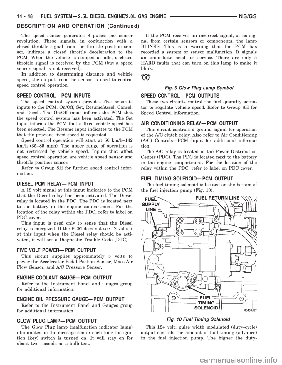
The Glow Plug lamp (malfunction indicator lamp)
illuminates on the message center each time the igni-
tion (key) switch is turned on. It will stay on for
about two seconds as a bulb test.If the PCM receives an incorrect signal, or no sig-
nal from certain sensors or components, the lamp
BLINKS. This is a warning that the PCM has
recorded a system or sensor malfunction. It signals
an immediate need for service. There are only 5
HARD faults that can turn on this lamp to make it
blink.
SPEED CONTROLÐPCM OUTPUTS
These two circuits control the fuel quantity actua-
tor to regulate vehicle speed. Refer to Group 8H for
Speed Control information.
AIR CONDITIONING RELAYÐPCM OUTPUT
This circuit controls a ground signal for operation
of the A/C clutch relay. Also refer to Air Conditioning
(A/C) ControlsÐPCM Input for additional informa-
tion.
The A/C relay is located in the Power Distribution
Center (PDC). The PDC is located next to the battery
in the engine compartment. For the location of the
relay within the PDC, refer to label on PDC cover.
FUEL TIMING SOLENOIDÐPCM OUTPUT
The fuel timing solenoid is located on the bottom of
the fuel injection pump (Fig. 10).
This 12+ volt, pulse width modulated (duty±cycle)
output controls the amount of fuel timing (advance)
in the fuel injection pump. The higher the duty-
Fig. 9 Glow Plug Lamp Symbol
Fig. 10 Fuel Timing Solenoid
14 - 48 FUEL SYSTEMÐ2.5L DIESEL ENGINE/2.0L GAS ENGINENS/GS
DESCRIPTION AND OPERATION (Continued)
Page 1427 of 1938
STEERING
CONTENTS
page page
GENERAL INFORMATION................... 1
POWER STEERING GEAR.................. 26POWER STEERING PUMP.................. 9
STEERING COLUMN...................... 36
GENERAL INFORMATION
INDEX
page page
GENERAL INFORMATION
STEERING SYSTEM AND COMPONENT
DESCRIPTION......................... 1DIAGNOSIS AND TESTING
STEERING SYSTEM DIAGNOSIS CHARTS..... 2
GENERAL INFORMATION
STEERING SYSTEM AND COMPONENT
DESCRIPTION
The power steering system consists of these four
major components. Power Steering Pump, Power
Steering Gear, Pressure Hose, and Return Line.
Turning of the steering wheel is converted into linear
travel through the meshing of the helical pinion
teeth with the rack teeth. Power assist steering is
provided by an open center, rotary type control valve.
It is used to direct oil from the pump to either side of
the integral steering rack piston.
Road feel is controlled by the diameter of a torsion
bar which initially steers the vehicle. As requiredsteering effort increases, as in a turn, the torsion bar
twists, causing relative rotary motion between the
rotary valve body and the valve spool. This move-
ment directs oil behind the integral rack piston,
which, in turn, builds up hydraulic pressure and
assists in the turning effort.
Drive tangs on the power steering gear pinion
shaft, mate loosely with the shaft of the steering
gear. This is to allow manual steering control to be
maintained, if the drive belt on the power steering
pump should break. However, under these conditions,
steering effort will significantly increase.
NSSTEERING 19 - 1
Page 1429 of 1938
CONDITION POSSIBLE CAUSES CORRECTION
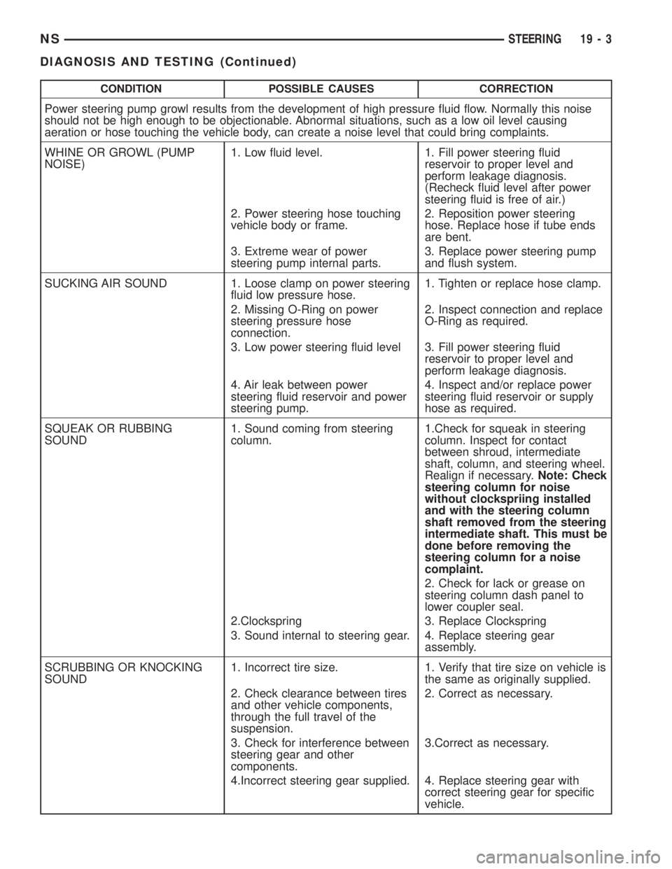
Power steering pump growl results from the development of high pressure fluid flow. Normally this noise
should not be high enough to be objectionable. Abnormal situations, such as a low oil level causing
aeration or hose touching the vehicle body, can create a noise level that could bring complaints.
WHINE OR GROWL (PUMP
NOISE)1. Low fluid level. 1. Fill power steering fluid
reservoir to proper level and
perform leakage diagnosis.
(Recheck fluid level after power
steering fluid is free of air.)
2. Power steering hose touching
vehicle body or frame.2. Reposition power steering
hose. Replace hose if tube ends
are bent.
3. Extreme wear of power
steering pump internal parts.3. Replace power steering pump
and flush system.
SUCKING AIR SOUND 1. Loose clamp on power steering
fluid low pressure hose.1. Tighten or replace hose clamp.
2. Missing O-Ring on power
steering pressure hose
connection.2. Inspect connection and replace
O-Ring as required.
3. Low power steering fluid level 3. Fill power steering fluid
reservoir to proper level and
perform leakage diagnosis.
4. Air leak between power
steering fluid reservoir and power
steering pump.4. Inspect and/or replace power
steering fluid reservoir or supply
hose as required.
SQUEAK OR RUBBING
SOUND1. Sound coming from steering
column.1.Check for squeak in steering
column. Inspect for contact
between shroud, intermediate
shaft, column, and steering wheel.
Realign if necessary.Note: Check
steering column for noise
without clockspriing installed
and with the steering column
shaft removed from the steering
intermediate shaft. This must be
done before removing the
steering column for a noise
complaint.
2. Check for lack or grease on
steering column dash panel to
lower coupler seal.
2.Clockspring 3. Replace Clockspring
3. Sound internal to steering gear. 4. Replace steering gear
assembly.
SCRUBBING OR KNOCKING
SOUND1. Incorrect tire size. 1. Verify that tire size on vehicle is
the same as originally supplied.
2. Check clearance between tires
and other vehicle components,
through the full travel of the
suspension.2. Correct as necessary.
3. Check for interference between
steering gear and other
components.3.Correct as necessary.
4.Incorrect steering gear supplied. 4. Replace steering gear with
correct steering gear for specific
vehicle.
NSSTEERING 19 - 3
DIAGNOSIS AND TESTING (Continued)
Page 1439 of 1938
(18) Remove the 3 previously loosened bolts
attaching the front bracket to the power steering
pump and separate the power steering pump from
the front bracket prior to removing the pump from
the vehicle.
(19) The power steering pump is removed from the
vehicle by pulling it out through the exhaust tunnel
area in the floor pan of the vehicle.
INSTALL
(1) Install power steering pump back in vehicle
using the reverse order of its removal through the
exhaust tunnel are of the vehicle.
(2) Install the power steering pump on its cast
mounting bracket and loosely install nut to hold
pump in place (Fig. 9).
(3) Install the front bracket on the power steering
pump and loosely install the 3 mounting bolts (Fig.
10). Then install the nut and bolt attaching the front
bracket to the cast bracket (Fig. 10).
(4) Tighten the 3 power steering pump mounting
bolts (Fig. 10) to a torque of 54 N´m (40 ft. lbs.).
NOTE: Before installing power steering fluid pres-
sure hose on power steering pump, inspect the
O-ring on the pressure hose for damage and
replace if necessary.
(5) Install the power steering fluid pressure line
onto the output fitting of the power steering pump
(Fig. 8). Tighten the pressure line to pump fitting
tube nut to a torque of 31 N´m (275 in. lbs.).
(6) Install the power steering fluid, low pressure
return hose on the power steering pump low pressure
fitting (Fig. 8).Be sure hose clamps are properly
reinstalled.
(7) Install the power steering fluid supply hose
from the power steering fluid reservoir, on the power
steering pump fluid fitting (Fig. 7).Be sure hose is
clear of accessory drive belts all hose clamps
are properly reinstalled.
(8) Install the power steering pump drive belt on
pulley. See Cooling, Group 7 for detailed installation
procedure.
(9) Install the accessory drive splash shield (Fig.
6).
(10) Install the power steering fluid return hose on
the steel tube at the front suspension cradle (Fig. 5).
(11) Install a screw type hose clamp on the power
steering hose to steel tube connection.Be sure hose
clamps are properly reinstalled.Tighten the screw
clamp to a torque of 2 N´m (18 in. lbs.).
CAUTION: The protective heat shield sleeves must
cover the entire rubber hose and hose to tube con-
nection portion of both the power steering fluid
pressure and return hoses (Fig. 5). This is requiredto prevent the overheating of the power steering
hoses.
(12) When used, properly position the protective
heat sleeves on the power steering hoses (Fig. 5).
Then, tie strap the heat sleeves to the power steering
hoses to keep them in their proper position.
(13) Install the exhaust pipe on the exhaust man-
ifold. Install all exhaust system hangers/isolators on
the exhaust system brackets.
(14) Connect the oxygen sensor wiring harness to
the vehicle wiring harness. Install wiring harness
grommet in the floor pan of the vehicle.
(15) Lower vehicle.
(16) Adjust the power steering pump drive belt.
See Cooling, Group 7 for detailed adjustment proce-
dure.
(17) Tighten the top nut and bottom bolt on the
power steering pump front mounting bracket (Fig. 3)
to a torque of 54 N´m (40 ft. lbs.).
CAUTION: Do not use automatic transmission fluid
in power steering system. Only use MoparT, Power
Steering Fluid, or equivalent.
(18) Fill the remote power steering pump fluid res-
ervoir to correct fluid level.
(19) Install cap on power steering fluid reservoir.
(20) Connect the negative battery cable on the
negative battery post.
(21) Start engine and turn steering wheel several
times from stop to stop to bleed air from fluid in sys-
tem. Stop engine, check fluid level, and inspect sys-
tem for leaks. See Checking Fluid Level.
3.0 LITER POWER STEERING PUMP
REMOVE
WARNING: POWER STEERING OIL, ENGINE COM-
PONENTS AND THE EXHAUST SYSTEM MAY BE
EXTREMELY HOT IF ENGINE HAS BEEN RUNNING.
DO NOT START ENGINE WITH ANY LOOSE OR DIS-
CONNECTED HOSES. DO NOT ALLOW HOSES TO
TOUCH HOT EXHAUST MANIFOLD OR CATALYST.
(1) Remove the (-) negative battery cable from the
battery and isolate cable.
(2) Remove cap from power steering fluid reser-
voir.
(3) Using a siphon pump, remove as much power
steering fluid as possible from the power steering
fluid reservoir.
NSSTEERING 19 - 13
REMOVAL AND INSTALLATION (Continued)
Page 1445 of 1938
cation and Maintenance section of this service man-
ual, for the required lifting procedure to be used for
this vehicle.
(5) Remove at power steering pump, the power
steering fluid hose coming from the power steering
fluid reservoir. Let the power steering fluid drain out
of the reservoir and hose.
(6) Lower vehicle.
(7) Remove hose clamp attaching the power steer-
ing fluid supply hose to the power steering fluid res-
ervoir (Fig. 24).
(8) Remove the power steering fluid supply hose
from the vehicle. Hose is removed from the top of the
engine compartment.
INSTALL
CAUTION: On V-6 engine applications, the power
steering fluid reservoir to power steering hose must
be routed tightly against the strut tower and parallel
to the dash panel. It must also be routed under the
wiring harness and below the drip tube. This rout-
ing will prevent the power steering fluid supply
hose from coming in contact with the accessory
drive belt.
(1) Install and correctly route the power steering
fluid supply hose from remote fluid reservoir down to
power steering pump.
(2) Install the fluid supply hose onto the power
steering fluid reservoir (Fig. 24). Install the hose
clamp on the fluid supply hose.Be sure hose clamp
is installed past bead on fluid reservoir fitting.
(3) Raise vehicle on jack stands or centered on a
frame contact type hoist. See Hoisting in the Lubri-
cation and Maintenance section of this service man-
ual, for the required lifting procedure to be used for
this vehicle.
(4) Install power steering fluid supply hose on
power steering pump. Install the hose clamp on the
fluid supply hose.Be sure hose clamp is installed
past bead on pump fitting.
(5) Lower vehicle.
(6) Install routing clip on power steering fluid sup-
ply hose. Be sure routing clip is installed in a posi-
tion to correctly align with stud in strut tower.
(7) Install routing clip for power steering fluid sup-
ply hose on stud in strut tower (Fig. 25).
(8) Fill the remote fluid reservoir to the proper
level and let the fluid settle for at least two (2) min-
utes.
(9) Start the engine and let run for a few seconds.
Then turn the engine off.
(10) Add fluid if necessary. Repeat the above pro-
cedure until the fluid level remains constant after
running the engine.
(11) Raise the front wheels off the ground.(12) Start the engine. Slowly turn the steering
wheel right and left, lightly contacting the wheel
stops.
(13) Add power steering fluid if necessary.
(14) Lower the vehicle and turn the steering wheel
slowly from lock to lock.
(15) Stop the engine. Check the fluid level and
refill as required.
(16) If the fluid is extremely foamy, allow the vehi-
cle to stand a few minutes and repeat the above pro-
cedure.
POWER STEERING FLUID PRESSURE HOSE
Service all power steering hoses with vehicle raised
on hoist. Cap all open ends of hoses, power steering
pump fittings and steering gear ports to prevent
entry of foreign material into the components.
WARNING: POWER STEERING OIL, ENGINE
PARTS AND THE EXHAUST SYSTEM MAY BE
EXTREMELY HOT IF ENGINE HAS BEEN RUNNING.
DO NOT START ENGINE WITH ANY LOOSE OR DIS-
CONNECTED HOSES. DO NOT ALLOW HOSES TO
TOUCH HOT EXHAUST MANIFOLD OR CATALYST.
For part reference and part location for the vehicle
that is being serviced, refer to the following figure
numbers. These show the hose bracket locations,
hose routings and fitting locations by the engine
application of the vehicle. Use these figure numbers
when referring to the removal or installation proce-
dures for the power steering hoses listed below.
REMOVE
(1) Remove cap from power steering fluid reser-
voir.
(2) Using a siphon pump, remove as much power
steering fluid as possible from the power steering
fluid reservoir.
(3) Raise vehicle See Hoisting, Group 0. Put oil
drain pan under vehicle to catch power steering fluid.
(4) Raise the heat sleeve on the power steering
fluid return hose (Fig. 26) to expose the return hose
to steel tube connection. Remove the hose clamp from
the power steering fluid return hose (Fig. 26).
Remove power steering fluid return hose from steel
tube and allow power steering fluid to drain from
pump.
NSSTEERING 19 - 19
REMOVAL AND INSTALLATION (Continued)
Page 1447 of 1938
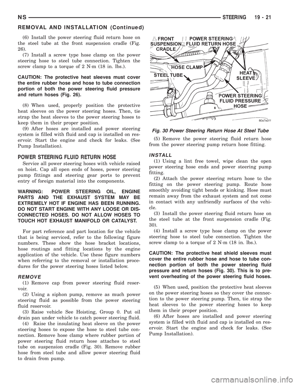
(6) Install the power steering fluid return hose on
the steel tube at the front suspension cradle (Fig.
26).
(7) Install a screw type hose clamp on the power
steering hose to steel tube connection. Tighten the
screw clamp to a torque of 2 N´m (18 in. lbs.).
CAUTION: The protective heat sleeves must cover
the entire rubber hose and hose to tube connection
portion of both the power steering fluid pressure
and return hoses (Fig. 26).
(8) When used, properly position the protective
heat sleeves on the power steering hoses. Then, tie
strap the heat sleeves to the power steering hoses to
keep them in their proper position.
(9) After hoses are installed and power steering
system is filled with fluid and cap is installed on res-
ervoir. Start the engine and check for leaks. (See
Pump Installation).
POWER STEERING FLUID RETURN HOSE
Service all power steering hoses with vehicle raised
on hoist. Cap all open ends of hoses, power steering
pump fittings and steering gear ports to prevent
entry of foreign material into the components.
WARNING: POWER STEERING OIL, ENGINE
PARTS AND THE EXHAUST SYSTEM MAY BE
EXTREMELY HOT IF ENGINE HAS BEEN RUNNING.
DO NOT START ENGINE WITH ANY LOOSE OR DIS-
CONNECTED HOSES. DO NOT ALLOW HOSES TO
TOUCH HOT EXHAUST MANIFOLD OR CATALYST.
For part reference and part location for the vehicle
that is being serviced, refer to the following figure
numbers. These show the hose bracket locations,
hose routings and fitting locations by the engine
application of the vehicle. Use these figure numbers
when referring to the removal or installation proce-
dures for the power steering hoses listed below.
REMOVE
(1) Remove cap from power steering fluid reser-
voir.
(2) Using a siphon pump, remove as much power
steering fluid as possible from the power steering
fluid reservoir.
(3) Raise vehicle See Hoisting, Group 0. Put oil
drain pan under vehicle to catch power steering fluid.
(4) Raise the insulating heat sleeve on the power
steering hoses to expose the hose to steel tube con-
nection. Remove hose clamp where rubber portion of
power steering fluid return hose attaches to steel
tube on suspension cradle (Fig. 30). Remove rubber
hose from steel tube and allow power steering fluid
to drain from pump.(5) Remove the power steering fluid return hose
from the power steering pump return hose fitting.
INSTALL
(1) Using a lint free towel, wipe clean the open
power steering hose ends and power steering pump
fitting.
(2) Attach the power steering return hose to the
fitting on the power steering pump. Route hose
smoothly avoiding tight bends or kinking. Hose must
remain away from the exhaust system and not come
in contact with any unfriendly surfaces of the vehi-
cle.
(3) Install the power steering fluid return hose on
the steel tube at the front suspension cradle (Fig.
30).
(4) Install a screw type hose clamp on the power
steering hose to steel tube connection. Tighten the
screw clamp to a torque of 2 N´m (18 in. lbs.).
CAUTION: The protective heat shield sleeves must
cover the entire rubber hose and hose to tube con-
nection portion of both the power steering fluid
pressure and return hoses (Fig. 30). This is to pre-
vent overheating of the power steering fluid hoses.
(5) When used, position the protective heat sleeves
on the power steering hoses so they cover the connec-
tion to the power steering pump. Then, tie strap the
heat sleeves to the power steering hoses to keep
them in their proper position.
(6) After hoses are installed and power steering
system is filled with fluid and cap is installed on res-
ervoir. Start the engine and check for leaks. (See
Pump Installation).
Fig. 30 Power Steering Return Hose At Steel Tube
NSSTEERING 19 - 21
REMOVAL AND INSTALLATION (Continued)
Page 1449 of 1938
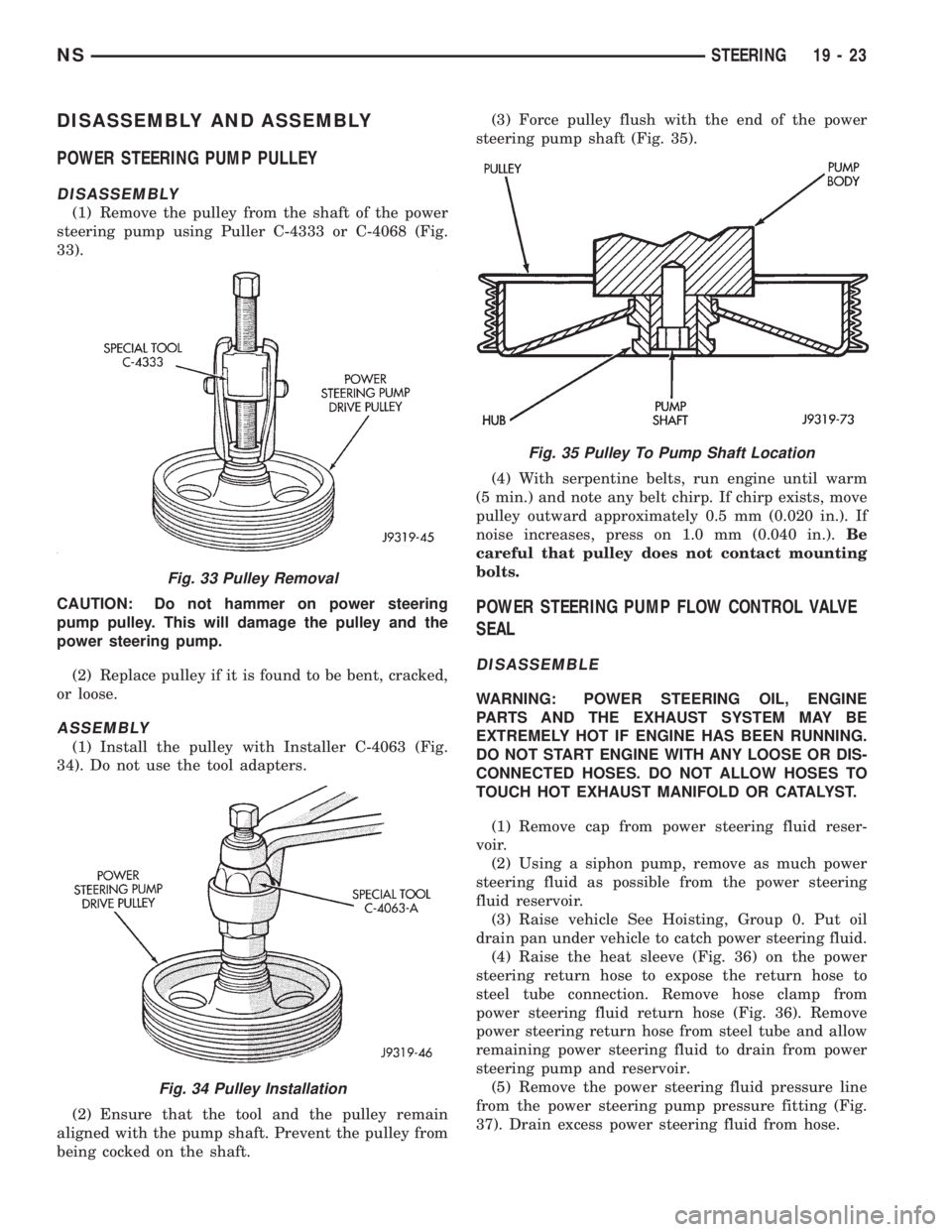
DISASSEMBLY AND ASSEMBLY
POWER STEERING PUMP PULLEY
DISASSEMBLY
(1) Remove the pulley from the shaft of the power
steering pump using Puller C-4333 or C-4068 (Fig.
33).
CAUTION: Do not hammer on power steering
pump pulley. This will damage the pulley and the
power steering pump.
(2) Replace pulley if it is found to be bent, cracked,
or loose.
ASSEMBLY
(1) Install the pulley with Installer C-4063 (Fig.
34). Do not use the tool adapters.
(2) Ensure that the tool and the pulley remain
aligned with the pump shaft. Prevent the pulley from
being cocked on the shaft.(3) Force pulley flush with the end of the power
steering pump shaft (Fig. 35).
(4) With serpentine belts, run engine until warm
(5 min.) and note any belt chirp. If chirp exists, move
pulley outward approximately 0.5 mm (0.020 in.). If
noise increases, press on 1.0 mm (0.040 in.).Be
careful that pulley does not contact mounting
bolts.
POWER STEERING PUMP FLOW CONTROL VALVE
SEAL
DISASSEMBLE
WARNING: POWER STEERING OIL, ENGINE
PARTS AND THE EXHAUST SYSTEM MAY BE
EXTREMELY HOT IF ENGINE HAS BEEN RUNNING.
DO NOT START ENGINE WITH ANY LOOSE OR DIS-
CONNECTED HOSES. DO NOT ALLOW HOSES TO
TOUCH HOT EXHAUST MANIFOLD OR CATALYST.
(1) Remove cap from power steering fluid reser-
voir.
(2) Using a siphon pump, remove as much power
steering fluid as possible from the power steering
fluid reservoir.
(3) Raise vehicle See Hoisting, Group 0. Put oil
drain pan under vehicle to catch power steering fluid.
(4) Raise the heat sleeve (Fig. 36) on the power
steering return hose to expose the return hose to
steel tube connection. Remove hose clamp from
power steering fluid return hose (Fig. 36). Remove
power steering return hose from steel tube and allow
remaining power steering fluid to drain from power
steering pump and reservoir.
(5) Remove the power steering fluid pressure line
from the power steering pump pressure fitting (Fig.
37). Drain excess power steering fluid from hose.
Fig. 33 Pulley Removal
Fig. 34 Pulley Installation
Fig. 35 Pulley To Pump Shaft Location
NSSTEERING 19 - 23