Page 998 of 1938

Component/
GroundColor Location Fig.
Left Rear
Reading LampGY At Lamp 17
Left Rear
Sliding Door
ContactBK LT B-Pillar 14
Left Rear
Sliding Door
Lock MotorBK At Motor N/S
Left Rear
SpeakerBK At Speaker 21
Left Rear Vent
MotorNAT At Motor 21
Left Rear Wheel
Speed SensorGY Center Rear of
Floor Pan16
Left Repeater
LampGY At Lamp N/S
Left Speed
Control SwitchLeft Side of
Steering Wheel
Pad11
Left Stop/Turn
Signal RelayBK LT Quarter
PanelN/S
Left Visor/Vanity
LampBK At Lamp 17
License Lamp GY At Lamps 23
Liftgate Ajar
SwitchBK At Latch 23
Liftgate
Arm/Disarm
SwitchGY At Key Cylinder 23
Liftgate Lock
MotorBK At Motor 23
LJ01 BK LT Quarter
Panel21
Low Note Horn BK LT Frame Rail 4
Low Washer
Fluid Level
SensorBK Bottom of
Reservior4
MAP Sensor
2.4LBK On Intake N/S
MAP Sensor
3.3L, 3.8LBK Near Throttle
Body9
Memort
Seat/Mirror
ModuleBK RT Front of
Floor Pan16
Memory Set
SwitchBL At Switch 19Component/
GroundColor Location Fig.
Message Center BL Rear of
Message
Center11
Mode Door
ActuatorBK LT Side of
HVAC15
Multi Function
SwitchBK Rear of Switch 11
Name Brand
Speaker RelayLT/GY LT of Steering
ColumnN/S
Output Shaft
Speed SensorGY Front of
Transmission7, 9
Overhead
ConsoleRD Front of
Console17
P18 GY RT of Steering
Column12
P30 BK RT Side of
HVAC10
P34 GY RT of Steering
Column12
P50 NAT Right Side of
HVAC Taped to
Harness10
Park Brake
SwitchNAT Top of Park
BrakeN/S
Park/Neutral
Positon SwitchBK Front of
TransmissionN/S
Passenger
AirbagYL Rear of Airbag 11
PDC C1 NAT Bottom of PDC 2
PDC C2 OR Bottom of PDC 2
PDC C3 DK/
GNBottom of PDC 2
PDC C4 BK Bottom of PDC 2
PDC C5 LT/GY Bottom of PDC 2
PDC C6 LT/GN Bottom of PDC 3
PDC C7 LT/GY Bottom of PDC 3
PDC C8 BL Bottom of PDC 3
Power Folding
Mirror SwitchBK At Switch N/S
Power Mirror
SwitchBK Rear of Switch 11
Power Steering
Pressure SwitchBK RT Side of
Engine
CompartmentN/S
8W - 90 - 34 8W - 90 CONNECTOR/GROUND LOCATIONSNS/GS
DESCRIPTION AND OPERATION (Continued)
Page 1283 of 1938

FRAME
INDEX
page page
REMOVAL AND INSTALLATION
FRONT CROSSMEMBER MOUNT BUSHINGS . . . 5
FRONT CROSSMEMBER................... 3SPECIFICATIONS
FRAME AND BODY OPENING DIMENSIONS.... 5
REMOVAL AND INSTALLATION
FRONT CROSSMEMBER
The front suspension crossmember must be
installed in the design location to achieve proper
front end suspension alignment. If the crossmember
is removed without applying reference marks on the
frame rails, align the crossmember according to the
dimensions provided in this group.
NOTE: If the caged nuts in the frame rails become
damaged and cannot be reused, a replacement nut
can be obtained through a MoparTParts supplier.
REMOVAL
(1) Disconnect battery negative cable.
(2) Remove steering column lower cover from
instrument panel. Refer to Group 8E, Instrument
Panel and Systems.
(3) Remove knee blocker reinforcement. Refer to
Group 8E, Instrument Panel and Systems.
(4) Position steering so front wheels are straight
ahead.
CAUTION: Do not rotate steering wheel after disen-
gaging lower coupling from steering gear, damage
to airbag clock spring can result.
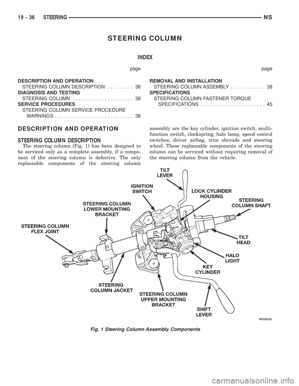
(5) Remove clinch bolt holding steering column
coupling to steering gear shaft (Fig. 1).
(6) Remove steering column coupling from tele-
scoping steering gear shaft.
(7) Hoist and support vehicle on safety stands.
(8) Position a drain pan under power steering
pump and oil return hose coupling.
(9) Using a hose pinch-off pliers (C-4390), pinch
power steering oil return hose off between the cross-
member coupling and the pump.
(10) Loosen hose clamp at the crossmember cou-
pling.
(11) Disconnect return hose from metal tube.
(12) While holding pressure relief valve nut on
back of power steering pump, Remove flare nut hold-
ing high pressure hose to back of pump.(13) Separate high pressure hose from pump.
(14) Allow power steering fluid to drain into pan.
(15) Remove bolts holding anti-lock brake sensor
leads to crossmember.
(16) Position anti-lock brake leads out of the way.
(17) Disconnect stabilizer bar links from ends of
stabilizer bar. Refer to Group 2, Suspension.
(18) Disconnect lower ball joints from lower control
arms. Refer to Group 2, Suspension.
(19) Remove bolt holding rear engine mount to
crossmember (Fig. 2).
(20) Using paint or grease pencil, mark outline of
crossmember on frame rails to aid installation.
(21) Support crossmember on suitable lifting
device (Fig. 4).
(22) Remove bolts holding crossmember to front
frame rails (Fig. 3).
(23) Remove crossmember from vehicle (Fig. 4).
Fig. 1 Steering Coupling Boot
NSFRAME AND BUMPERS 13 - 3
Page 1462 of 1938

STEERING COLUMN
INDEX
page page
DESCRIPTION AND OPERATION
STEERING COLUMN DESCRIPTION......... 36
DIAGNOSIS AND TESTING
STEERING COLUMN..................... 38
SERVICE PROCEDURES
STEERING COLUMN SERVICE PROCEDURE
WARNINGS........................... 38REMOVAL AND INSTALLATION
STEERING COLUMN ASSEMBLY............ 38
SPECIFICATIONS
STEERING COLUMN FASTENER TORQUE
SPECIFICATIONS...................... 45
DESCRIPTION AND OPERATION
STEERING COLUMN DESCRIPTION
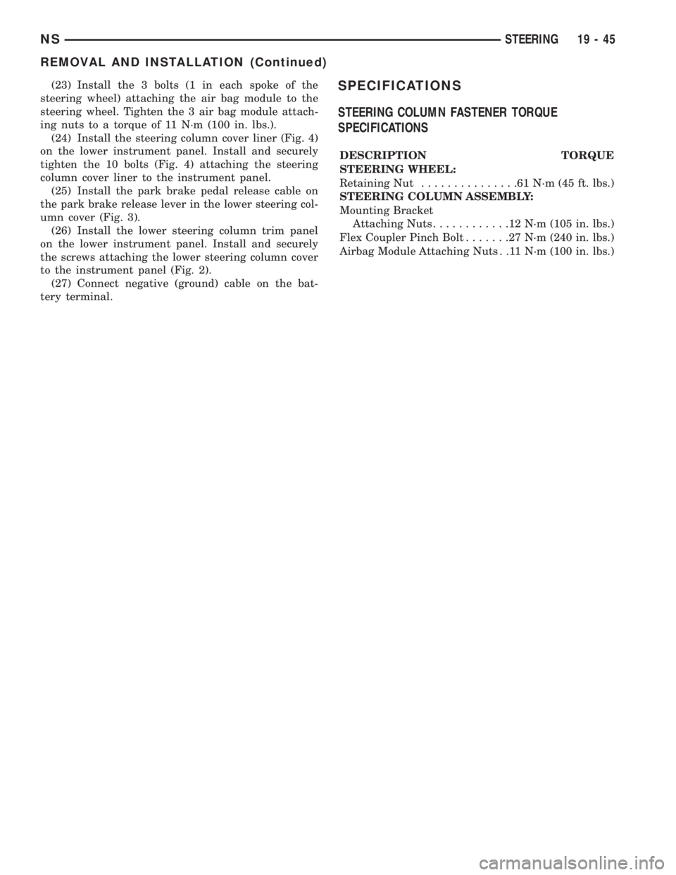
The steering column (Fig. 1) has been designed to
be serviced only as a complete assembly, if a compo-
nent of the steering column is defective. The only
replaceable components of the steering columnassembly are the key cylinder, ignition switch, multi-
function switch, clockspring, halo lamp, speed control
switches, driver airbag, trim shrouds and steering
wheel. These replaceable components of the steering
column can be serviced without requiring removal of
the steering column from the vehicle.
Fig. 1 Steering Column Assembly Components
19 - 36 STEERINGNS
Page 1471 of 1938

(23) Install the 3 bolts (1 in each spoke of the
steering wheel) attaching the air bag module to the
steering wheel. Tighten the 3 air bag module attach-
ing nuts to a torque of 11 N´m (100 in. lbs.).
(24) Install the steering column cover liner (Fig. 4)
on the lower instrument panel. Install and securely
tighten the 10 bolts (Fig. 4) attaching the steering
column cover liner to the instrument panel.
(25) Install the park brake pedal release cable on
the park brake release lever in the lower steering col-
umn cover (Fig. 3).
(26) Install the lower steering column trim panel
on the lower instrument panel. Install and securely
the screws attaching the lower steering column cover
to the instrument panel (Fig. 2).
(27) Connect negative (ground) cable on the bat-
tery terminal.SPECIFICATIONS
STEERING COLUMN FASTENER TORQUE
SPECIFICATIONS
DESCRIPTION TORQUE
STEERING WHEEL:
Retaining Nut...............61N´m(45ft.lbs.)
STEERING COLUMN ASSEMBLY:
Mounting Bracket
Attaching Nuts............12N´m(105 in. lbs.)
Flex Coupler Pinch Bolt.......27N´m(240 in. lbs.)
Airbag Module Attaching Nuts . .11 N´m (100 in. lbs.)
NSSTEERING 19 - 45
REMOVAL AND INSTALLATION (Continued)
Page 1806 of 1938

(2) If equipped, remove pop-rivets holding molding
edge to wheelhouse lip.
(3) Pull stick-on molding from painted surface.
(4) Remove adhesive tape residue from painted
surface of vehicle. Use a 3M Scotch-BriteyMolding
Adhesive and Stripe Removal Disc, or equivalent, to
clean adhesive residue from painted surfaces. These
products are available from automotive paint suppli-
ers. Refer to instructions supplied with the specific
product for proper usage.
INSTALLATION
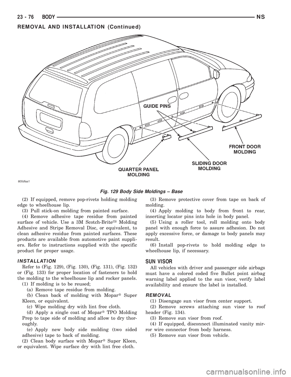
Refer to (Fig. 129), (Fig. 130), (Fig. 131), (Fig. 132)
or (Fig. 133) for proper location of fasteners to hold
the molding to the wheelhouse lip and rocker panels.
(1) If molding is to be reused;
(a) Remove tape residue from molding.
(b) Clean back of molding with MopartSuper
Kleen, or equivalent.
(c) Wipe molding dry with lint free cloth.
(d) Apply a single coat of MopartTPO Molding
Prep to tape side of molding and allow to dry thor-
oughly.
(e) Apply new body side molding (two sided
adhesive) tape to back of molding.
(2) Clean body surface with MopartSuper Kleen,
or equivalent. Wipe surface dry with lint free cloth.(3) Remove protective cover from tape on back of
molding.
(4) Apply molding to body from front to rear,
inserting locator pins into hole in body panel.
(5) Using a roller tool, roll molding onto body
panel with enough force to assure adhesion. Do not
apply excessive force, or damage to body panels may
result.
(6) Install pop-rivets to hold molding edge to
wheelhouse lip, if necessary.
SUN VISOR
All vehicles with driver and passenger side airbags
must have a colored coded five Bullet point airbag
warning label applied to the sun visor, verify label
availability and ensure the label is installed.
REMOVAL
(1) Disengage sun visor from center support.
(2) Remove screws attaching sun visor to roof
header (Fig. 134).
(3) Remove sun visor from roof.
(4) If equipped, disconnect illuminated vanity mir-
ror wire connector from body harness.
(5) Remove sun visor from vehicle.
Fig. 129 Body Side Moldings ± Base
23 - 76 BODYNS
REMOVAL AND INSTALLATION (Continued)