1996 CHRYSLER VOYAGER power steering
[x] Cancel search: power steeringPage 970 of 1938

Component/
GroundColor Location Fig.
Right Door
Arm/Disarm
SwitchBK At Switch 17
Right Door
Courtesy LampBK At Lamp 17
Right Door
SpeakerBK At Speaker 17
Right Flasher
RelayBK LT Quarter
PanelN/S
Right Front Fog
LampBK At Lamp 4
Right Front
Door Ajar
SwitchBK RT B-Pillar 12
Right Front
Door Lock
MotorBK At Motor 17
Right Front
Panel SpeakerBK At Speaker 11
Right Front
Park/Turn
Signal LampBK At Lamp 4
Right Front
Wheel Speed
SensorBK Right Fender
Side Shield4
Right Front
Window MotorRD At Motor 19
Right Headlamp BK At Lamp 4
Right Headlamp
Leveling MotorBK At Motor N/S
Right Liftgate
Flood LampBK At Lamp 23
Right Mid
Reading LampGY At Lamp 17
Right Power
Door Lock
SwitchBK At Switch 19
Right Power
Mirror C1RD At Mirror 11
Right Power
Mirror C2BL At Mirror 11
Right Power
Window SwitchBK At Switch 19
Right Rear
Lamp AssemblyBK At Lamp 22
Right Rear Door
Ajar SwitchBK RT C-Pillar 22Component/
GroundColor Location Fig.
Right Rear Pillar
SpeakerBK At Speaker 22
Right Rear
Reading LampGY At Lamp 17
Right Rear
Sliding Door
ContactBK RT B-Pillar 14
Right Rear
Sliding Door
Lock MotorBK At Motor N/S
Right Rear
SpeakerBK At Speaker 22
Right Rear Vent
MotorNAT At Motor 22
Right Rear
Wheel Speed
SensorBK Center Rear of
Floor Pan16
Right Repeater
LampGY At Lamp N/S
Right Speed
Control SwitchRight Side of
Steering Wheel
Pad11
Right Stop/Turn
Signal RelayBK LT Quarter
PanelN/S
Right Visor/
Vanity LampBK At Lamp 17
S02 BK Under Seat N/S
Seat Belt Switch BK LT B-Pillar N/S
Sentry Key
Immobilizer
ModuleBK Near Steering
at Module11
Stop Lamp
SwitchGY Top of Brake
Pedal13
T05 BK LT Quarter
PanelN/S
T08 BK LT Quarter
PanelN/S
Throttle Position
SensorNAT On Throttle
Body5, 6, 7,
8, 9
Trailer Tow
ConnectorBK LT Quarter
PanelN/S
Transmission
Control ModuleBK RT Fender Side
Shield3
Transmission
Range SensorBK Top of
Transmission7, 9
8W - 90 - 6 8W - 90 CONNECTOR/GROUND LOCATIONSNS/GS
DESCRIPTION AND OPERATION (Continued)
Page 998 of 1938

Component/
GroundColor Location Fig.
Left Rear
Reading LampGY At Lamp 17
Left Rear
Sliding Door
ContactBK LT B-Pillar 14
Left Rear
Sliding Door
Lock MotorBK At Motor N/S
Left Rear
SpeakerBK At Speaker 21
Left Rear Vent
MotorNAT At Motor 21
Left Rear Wheel
Speed SensorGY Center Rear of
Floor Pan16
Left Repeater
LampGY At Lamp N/S
Left Speed
Control SwitchLeft Side of
Steering Wheel
Pad11
Left Stop/Turn
Signal RelayBK LT Quarter
PanelN/S
Left Visor/Vanity
LampBK At Lamp 17
License Lamp GY At Lamps 23
Liftgate Ajar
SwitchBK At Latch 23
Liftgate
Arm/Disarm
SwitchGY At Key Cylinder 23
Liftgate Lock
MotorBK At Motor 23
LJ01 BK LT Quarter
Panel21
Low Note Horn BK LT Frame Rail 4
Low Washer
Fluid Level
SensorBK Bottom of
Reservior4
MAP Sensor
2.4LBK On Intake N/S
MAP Sensor
3.3L, 3.8LBK Near Throttle
Body9
Memort
Seat/Mirror
ModuleBK RT Front of
Floor Pan16
Memory Set
SwitchBL At Switch 19Component/
GroundColor Location Fig.
Message Center BL Rear of
Message
Center11
Mode Door
ActuatorBK LT Side of
HVAC15
Multi Function
SwitchBK Rear of Switch 11
Name Brand
Speaker RelayLT/GY LT of Steering
ColumnN/S
Output Shaft
Speed SensorGY Front of
Transmission7, 9
Overhead
ConsoleRD Front of
Console17
P18 GY RT of Steering
Column12
P30 BK RT Side of
HVAC10
P34 GY RT of Steering
Column12
P50 NAT Right Side of
HVAC Taped to
Harness10
Park Brake
SwitchNAT Top of Park
BrakeN/S
Park/Neutral
Positon SwitchBK Front of
TransmissionN/S
Passenger
AirbagYL Rear of Airbag 11
PDC C1 NAT Bottom of PDC 2
PDC C2 OR Bottom of PDC 2
PDC C3 DK/
GNBottom of PDC 2
PDC C4 BK Bottom of PDC 2
PDC C5 LT/GY Bottom of PDC 2
PDC C6 LT/GN Bottom of PDC 3
PDC C7 LT/GY Bottom of PDC 3
PDC C8 BL Bottom of PDC 3
Power Folding
Mirror SwitchBK At Switch N/S
Power Mirror
SwitchBK Rear of Switch 11
Power Steering
Pressure SwitchBK RT Side of
Engine
CompartmentN/S
8W - 90 - 34 8W - 90 CONNECTOR/GROUND LOCATIONSNS/GS
DESCRIPTION AND OPERATION (Continued)
Page 1039 of 1938
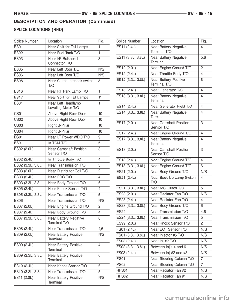
SPLICE LOCATIONS (RHD)
Splice Number Location Fig.
BS01 Near Split for Tail Lamps 11
BS02 Near Fuel Tank T/O 11
BS03 Near I/P Bulkhead
Connector T/O8
BS05 Near Left Door T/O N/S
BS06 Near Left Door T/O N/S
BS08 Near Clutch Interlock switch
T/O8
BS16 Near RT Park Lamp T/O 1
BS17 Near Split for Tail Lamps 11
BS31 Near Left Headlamp
Leveling Motor T/O1
CS01 Above Right Rear Door 10
CS02 Above Right Rear Door 10
CS03 Right B-Pillar 10
CS04 Right B-Pillar 10
DS01 Near LT Power WDO T/O 9
ES01 In TCM T/O 6
ES02 (2.0L) Near Camshaft Position
Sensor T/O3
ES02 (2.4L) In Throttle Body T/O 4
ES02 (3.3L, 3.8L) Near Transmission T/O 5
ES03 (2.0L) Near Distributor Coil T/O 2
ES03 (2.4L) Near PDC T/O 4
ES03 (3.3L, 3.8L) Near Body Ground T/O 6
ES05 (2.4L) Near Knock Sensor T/O 4
ES05 (3.3L, 3.8L) Near Transmission T/O 5
ES06 Near Transmission T/O N/S
ES07 (2.0L) Near Engine Ground T/O 2
ES07 (2.4L) Near Body Ground T/O 4
ES07 (3.3L, 3.8L) Near Battery Negative
Terminal T/O6
ES08 (2.4L) Near Transmission T/O 4,6
ES09 (2.0L) Near Battery Positive
TerminalN/S
ES09 (2.4L) Near Battery Positive
Terminal4
ES09 (3.3L, 3.8L) Near Battery Positive
Terminal6
ES10 (2.4L) Near Knock Sensor T/O 6
ES10 (3.3L, 3.8L) Near Transmission T/O 5
ES11 (2.0L) Near Battery Positive
TerminalN/SSplice Number Location Fig.
ES11 (2.4L) Near Battery Negative
Terminal T/O4
ES11 (3.3L, 3.8L) Near Battery Negative
Terminal5,6
ES12 (2.0L) Near Engine Ground T/O 2
ES12 (2.4L) Near Throttle Body T/O 4
ES12 (3.3L, 3.8L) Near Battery Positive
Terminal T/O6
ES13 (2.4L) Near Generator T/O 4
ES13 (3.3L, 3.8L) Near Battery Negative
Terminal4
ES14 (2.4L) Near Generator Field T/O 4
ES14 (3.3L, 3.8L) Near Battery Negative
Terminal4
ES17 (2.0L) Near Camshaft Position
Sensor T/O3
ES17 (2.4L) Near Engine Ground T/O 4
ES17 (3.3L, 3,8L) Near Battery Negative
Terminal4
ES18 (2.0L) Near Camshaft Position
Sensor T/O3
ES18 (2.4L) Near Engine Ground T/O 4
ES18 (3.3L, 3.8L) Near Engine Ground T/O 6
ES21 (2.0L) Near Body Ground T/O N/S
ES21 (2.4L) Near Back Up Lamp Switch
T/O4
ES21 (3.3L, 3.8L) Near A/C Clutch T/O 5
ES23 (2.0L) Near Radiator Fan T/O N/S
ES23 (2.4L) Near Radiator Fan T/O 4
ES23 (3.3L, 3.8L) Near Body Ground T/O 6
ES24 Near Transmission T/O 4,6
ES24 (3.3L, 3.8L) Near Transmission T/O 5
ES99 (2.0L) Near Knock Sensor T/O 2
FS01 (2.4L) Near ECT Sensor T/O N/S
FS01 (3.3L, 3.8L) Near Injector #5 T/O N/S
FS02 (2.4L) Near Inj #2 T/O N/S
FS02 (3.3L, 3.8L) Between Inj's 4 and 6 N/S
FS03 (2.4L) Between Inj #2 and #3 N/S
PS01 Near Steering Column T/O 7
PS02 Near Steering Column T/O 7
RFS01 Near Radiator Fan #2 N/S
RFS02 Near Radiator Fan #1 N/S
NS/GS8W - 95 SPLICE LOCATIONS 8W - 95 - 15
DESCRIPTION AND OPERATION (Continued)
Page 1076 of 1938
ENGINE ASSEMBLY
REMOVAL
(1) Perform fuel pressure release procedure. Refer
to Group 14, Fuel System for procedure. Remove fuel
line to fuel rail.
(2) Disconnect battery.
(3) Remove Air cleaner and hoses.
(4) Drain cooling system. Refer to Group 7, Cooling
System for procedure.
(5) Remove upper radiator hose and remove radia-
tor fans. Refer to Group 7, Cooling System for proce-
dure.
(6) Remove lower radiator hose.
(7) Disconnect automatic transmission cooler lines
and plug, if equipped.
(8) Disconnect transmission shift linkage.
(9) Disconnect throttle body linkage.
(10) Disconnect engine wiring harness.
(11) Disconnect heater hoses.
(12) Discharge Air Conditioning System. Refer to
Group 24, Air Conditioning for procedure.
(13) Hoist vehicle and remove right inner splash
shield. Remove wheels and tires.
(14) Loosen power steering belt for pump removal.
Refer to Group 7, Cooling System for procedure.
(15) Remove axle shafts. Refer to Group 2, Suspen-
sion and Driveshafts for procedure.
(16) Disconnect exhaust pipe from manifold.
(17) Remove front and rear engine mount brackets
from the body.
(18) Remove bending braces and front engine
mount bracket. Remove transmission inspection
cover.
(19) Mark flexplate to torque converter and
remove torque converter bolts.
(20) Install front engine mount bracket.
(21) Lower vehicle.
(22) Remove power steering pump. Set pump
aside.
(23) Remove A/C lines at compressor and cap.
(24) Remove ground straps to body.
(25) Raise vehicle enough to allow engine dolly
Special Tool 6135, cradle Special Tool 6710 with
Posts Special Tool 6848 and Adaptor Special Tool
8130 to be installed under vehicle (Fig. 27).
(26) Loosen cradle posts to allow movement for
proper positioning. Locate two rear posts (right side
of engine) into the holes on the engine bedplate.
Locate the two front posts (left side of engine) on the
front engine bracket and A/C compressor bracket
(Fig. 27). Lower vehicle and position cradle mounts
until the engine is resting on mounts. Tighten
mounts to cradle frame. This will keep mounts from
moving when removing or installing engine and
transmission.(27) Lower vehicle so the weight ofONLY THE
ENGINE AND TRANSMISSIONare on the cradle.
(28) Remove engine and transmission mount bolts.
(29) Raise vehicle slowly. It may be necessary to
move the engine/transmission assembly on the cradle
to allow for removal around the body.
INSTALLATION
(1) Position engine and transmission assembly
under vehicle and slowly lower the vehicle over the
engine and transmission.
(2) Align engine and transmission mounts to
attaching points. Install mounting bolts at the right
engine and left transmission mounts. Refer to proce-
dures outlined in this section.
(3) Slowly raise vehicle enough to remove the
engine dolly and cradle Special Tools 6135 and 6710.
(4) Install axle shafts. Refer to Group 2, Suspen-
sion and Driveshafts for procedure.
(5) Install transmission and engine braces and
splash shields.
(6) Connect exhaust system to manifold. Refer to
Group 11, Exhaust System and Intake Manifold for
procedure and torque specifications.
(7) Install power steering pump. Refer to Cooling
System Group 7, Accessory Drive Section for belt ten-
sion adjustment.
(8) Install A/C compressor hoses. Refer to Group
24, Heater and Air Conditioning for procedure.
(9) Install accessory drive belts. Refer to Group 7,
Cooling System Accessory Drive Section for belt ten-
sion adjustment.
(10) Install front and rear engine mounts. Refer to
this section for procedure.
(11) Install inner splash shield. Install wheels and
tires.
(12) Connect automatic transmission cooler lines,
and shift linkage. Refer to Group 21, Transmission
for procedures.
(13) Connect fuel line and heater hoses.
(14) Install ground straps. Connect engine and
throttle body connections and harnesses. Refer to
Group 8, Electrical for procedure.
(15) Connect throttle body linkage. Refer to Group
14, Fuel System for procedure.
(16) Install radiator fans. Install radiator hoses.
Fill cooling system. Refer to Group 7, Cooling System
for filling procedure.
(17) Connect battery.
(18) Install air cleaner and hoses.
(19) Install oil filter. Fill engine crankcase with
proper oil to correct level.
(20) Start engine and run until operating temper-
ature is reached.
(21) Adjust transmission linkage, if necessary.
9 - 26 2.4L ENGINENS
REMOVAL AND INSTALLATION (Continued)
Page 1084 of 1938
CYLINDER HEAD
REMOVAL
(1) Perform fuel system pressure release proce-
durebefore attempting any repairs.Refer to
Group 14, Fuel System for procedure.
(2) Disconnect negative battery cable. Drain cool-
ing system. Refer to Group 7, Cooling System for pro-
cedure.
(3) Remove air cleaner and disconnect all vacuum
lines, electrical wiring and fuel lines from throttle
body.
(4) Remove throttle linkage. Refer to Group 14,
Fuel System for procedures
(5) Remove accessory drive belts. Refer to Group
7, Cooling System for procedure.
(6) Remove power brake vacuum hose from intake
manifold.
(7) Raise vehicle and remove exhaust pipe from
manifold.(8) Remove power steering pump assembly and
set aside.
(9) Disconnect coil pack wiring connector and
remove coil pack and plug wires from engine.
(10) Remove cam sensor and fuel injectors wiring
connectors.
(11) Remove timing belt and camshaft sprocket.
Refer to procedure outlined in this section.
(12) Remove timing belt idler pulley and rear tim-
ing belt cover.
(13) Remove cylinder head cover using procedure
outlined in this section.
(14) Remove camshafts and cam followers. Refer to
procedures outlined in this section for procedures.
(15) Remove cylinder head bolts and remove cyl-
inder head from engine block.
(16) Inspect and clean cylinder head. Refer to
Cleaning and Inspection outlined in this section for
procedures.
INSTALLATION
NOTE: The Cylinder head bolts should be exam-
ined BEFORE reuse. If the threads are necked
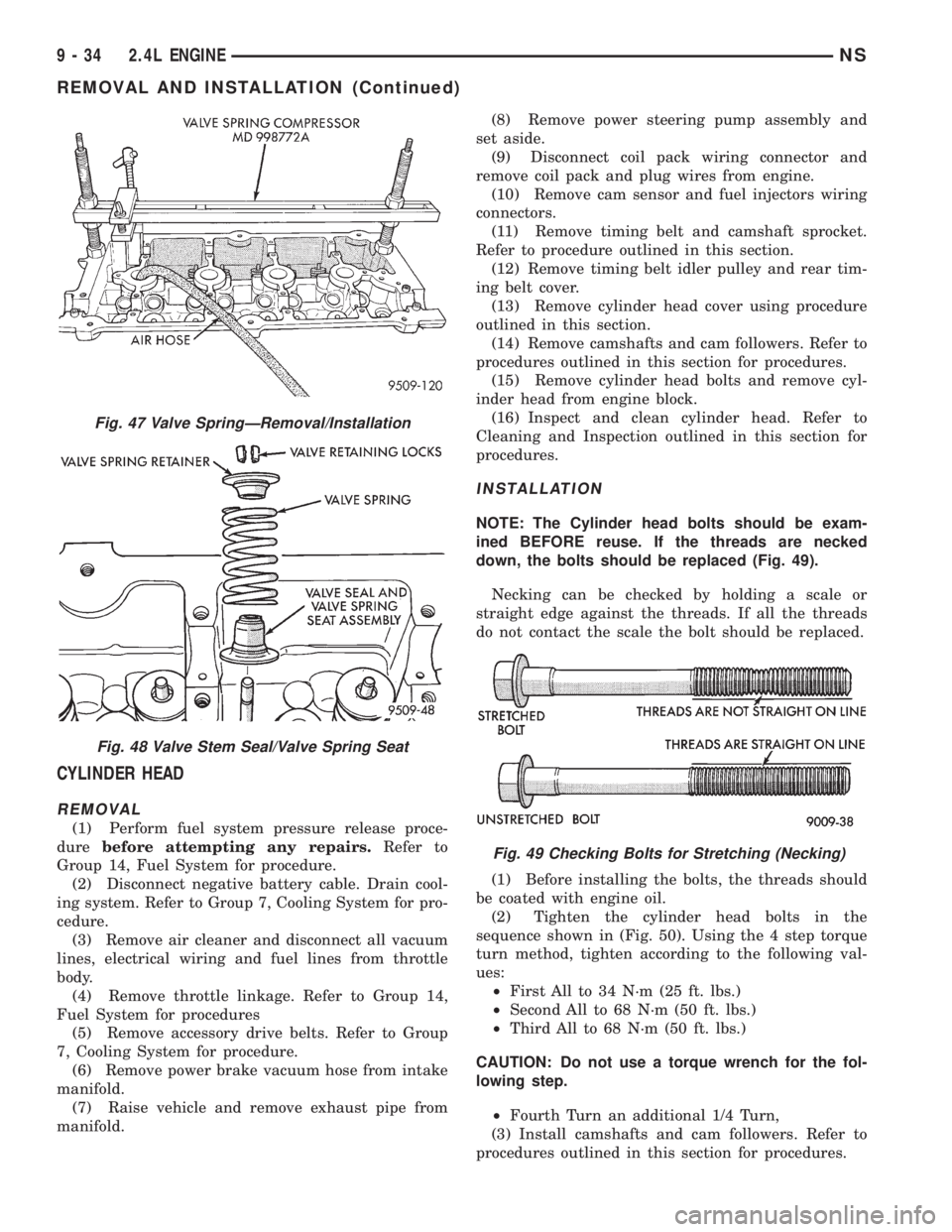
down, the bolts should be replaced (Fig. 49).
Necking can be checked by holding a scale or
straight edge against the threads. If all the threads
do not contact the scale the bolt should be replaced.
(1) Before installing the bolts, the threads should
be coated with engine oil.
(2) Tighten the cylinder head bolts in the
sequence shown in (Fig. 50). Using the 4 step torque
turn method, tighten according to the following val-
ues:
²First All to 34 N´m (25 ft. lbs.)
²Second All to 68 N´m (50 ft. lbs.)
²Third All to 68 N´m (50 ft. lbs.)
CAUTION: Do not use a torque wrench for the fol-
lowing step.
²Fourth Turn an additional 1/4 Turn,
(3) Install camshafts and cam followers. Refer to
procedures outlined in this section for procedures.
Fig. 47 Valve SpringÐRemoval/Installation
Fig. 48 Valve Stem Seal/Valve Spring Seat
Fig. 49 Checking Bolts for Stretching (Necking)
9 - 34 2.4L ENGINENS
REMOVAL AND INSTALLATION (Continued)
Page 1085 of 1938
(4) Install cylinder head cover using procedure out-
lined in this section.
(5) Install rear timing belt cover and timing belt
idler pulley.
(6) Install timing belt and camshaft sprocket.
Refer to procedure outlined in this section.
(7) Install cam sensor and fuel injectors wiring
connectors.
(8) Install coil pack and plug wires onto the
engine. Connect coil pack wiring connector.
(9) Install power steering pump assembly.
(10) Raise vehicle and install the exhaust pipe to
the manifold.
(11) Install power brake vacuum hose to the intake
manifold.
(12) Install accessory drive belts. Refer to Group 7,
Cooling System for procedure.
(13) Install throttle linkage. Refer to Group 14,
Fuel System for procedures.
(14) Install air cleaner and connect all vacuum
lines, electrical wiring and fuel lines to the throttle
body.
(15) Fill cooling system. Refer to Group 7, Cooling
System for procedure. Connect negative battery
cable.
VALVES AND VALVE SPRINGS
REMOVAL
(1) With cylinder head removed, compress valve
springs using a universal valve spring compressor.
(2) Remove valve retaining locks, valve spring
retainers, valve stem seals and valve springs.(3) Before removing valves,remove any burrs
from valve stem lock grooves to prevent dam-
age to the valve guides.Identify valves to insure
installation in original location.
(4) Inspect and clean the valves. Refer to Cleaning
and Inspection outlined in this section for procedure.
INSTALLATION
(1) Coat valve stems with clean engine oil and
insert in cylinder head.
(2) Install new valve stem seals on all valves
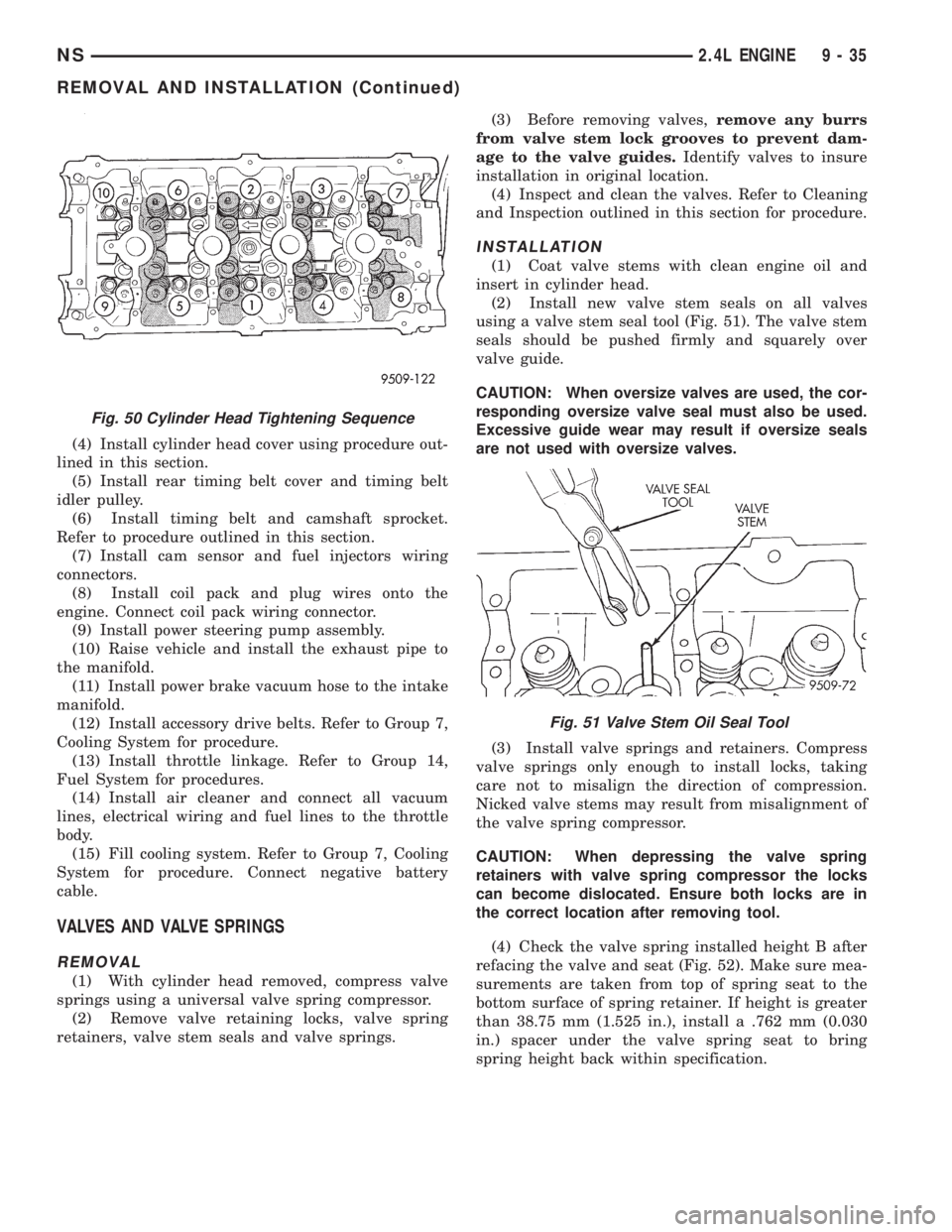
using a valve stem seal tool (Fig. 51). The valve stem
seals should be pushed firmly and squarely over
valve guide.
CAUTION: When oversize valves are used, the cor-
responding oversize valve seal must also be used.
Excessive guide wear may result if oversize seals
are not used with oversize valves.
(3) Install valve springs and retainers. Compress
valve springs only enough to install locks, taking
care not to misalign the direction of compression.
Nicked valve stems may result from misalignment of
the valve spring compressor.
CAUTION: When depressing the valve spring
retainers with valve spring compressor the locks
can become dislocated. Ensure both locks are in
the correct location after removing tool.
(4) Check the valve spring installed height B after
refacing the valve and seat (Fig. 52). Make sure mea-
surements are taken from top of spring seat to the
bottom surface of spring retainer. If height is greater
than 38.75 mm (1.525 in.), install a .762 mm (0.030
in.) spacer under the valve spring seat to bring
spring height back within specification.
Fig. 50 Cylinder Head Tightening Sequence
Fig. 51 Valve Stem Oil Seal Tool
NS2.4L ENGINE 9 - 35
REMOVAL AND INSTALLATION (Continued)
Page 1119 of 1938
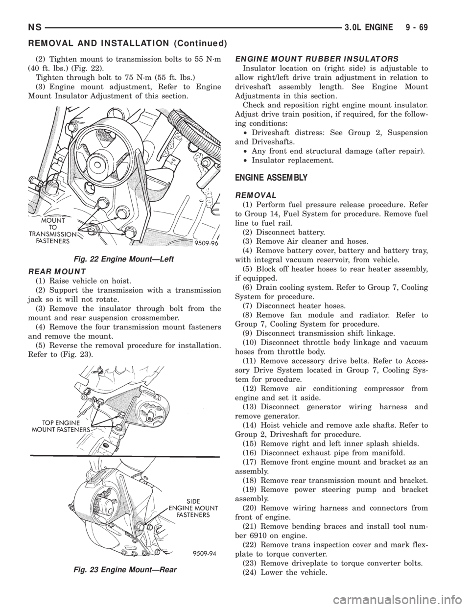
(2) Tighten mount to transmission bolts to 55 N´m
(40 ft. lbs.) (Fig. 22).
Tighten through bolt to 75 N´m (55 ft. lbs.)
(3) Engine mount adjustment, Refer to Engine
Mount Insulator Adjustment of this section.
REAR MOUNT
(1) Raise vehicle on hoist.
(2) Support the transmission with a transmission
jack so it will not rotate.
(3) Remove the insulator through bolt from the
mount and rear suspension crossmember.
(4) Remove the four transmission mount fasteners
and remove the mount.
(5) Reverse the removal procedure for installation.
Refer to (Fig. 23).
ENGINE MOUNT RUBBER INSULATORS
Insulator location on (right side) is adjustable to
allow right/left drive train adjustment in relation to
driveshaft assembly length. See Engine Mount
Adjustments in this section.
Check and reposition right engine mount insulator.
Adjust drive train position, if required, for the follow-
ing conditions:
²Driveshaft distress: See Group 2, Suspension
and Driveshafts.
²Any front end structural damage (after repair).
²Insulator replacement.
ENGINE ASSEMBLY
REMOVAL
(1) Perform fuel pressure release procedure. Refer
to Group 14, Fuel System for procedure. Remove fuel
line to fuel rail.
(2) Disconnect battery.
(3) Remove Air cleaner and hoses.
(4) Remove battery cover, battery and battery tray,
with integral vacuum reservoir, from vehicle.
(5) Block off heater hoses to rear heater assembly,
if equipped.
(6) Drain cooling system. Refer to Group 7, Cooling
System for procedure.
(7) Disconnect heater hoses.
(8) Remove fan module and radiator. Refer to
Group 7, Cooling System for procedure.
(9) Disconnect transmission shift linkage.
(10) Disconnect throttle body linkage and vacuum
hoses from throttle body.
(11) Remove accessory drive belts. Refer to Acces-
sory Drive System located in Group 7, Cooling Sys-
tem for procedure.
(12) Remove air conditioning compressor from
engine and set it aside.
(13) Disconnect generator wiring harness and
remove generator.
(14) Hoist vehicle and remove axle shafts. Refer to
Group 2, Driveshaft for procedure.
(15) Remove right and left inner splash shields.
(16) Disconnect exhaust pipe from manifold.
(17) Remove front engine mount and bracket as an
assembly.
(18) Remove rear transmission mount and bracket.
(19) Remove power steering pump and bracket
assembly.
(20) Remove wiring harness and connectors from
front of engine.
(21) Remove bending braces and install tool num-
ber 6910 on engine.
(22) Remove trans inspection cover and mark flex-
plate to torque converter.
(23) Remove driveplate to torque converter bolts.
(24) Lower the vehicle.
Fig. 22 Engine MountÐLeft
Fig. 23 Engine MountÐRear
NS3.0L ENGINE 9 - 69
REMOVAL AND INSTALLATION (Continued)
Page 1120 of 1938
(25) Remove ground straps to body.
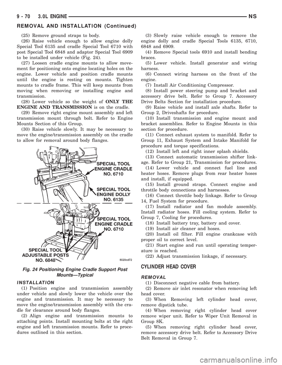
(26) Raise vehicle enough to allow engine dolly
Special Tool 6135 and cradle Special Tool 6710 with
post Special Tool 6848 and adaptor Special Tool 6909
to be installed under vehicle (Fig. 24).
(27) Loosen cradle engine mounts to allow move-
ment for positioning onto engine locating holes on the
engine. Lower vehicle and position cradle mounts
until the engine is resting on mounts. Tighten
mounts to cradle frame. This will keep mounts from
moving when removing or installing engine and
transmission.
(28) Lower vehicle so the weight ofONLY THE
ENGINE AND TRANSMISSIONis on the cradle.
(29) Remove right engine mount assembly and left
transmission mount through bolt. Refer to Engine
Mounts Section of this Group.
(30) Raise vehicle slowly. It may be necessary to
move the engine/transmission assembly on the cradle
to allow for removal around body flanges.
INSTALLATION
(1) Position engine and transmission assembly
under vehicle and slowly lower the vehicle over the
engine and transmission. It may be necessary to
move the engine/transmission assembly with the cra-
dle for clearance around body flanges.
(2) Align engine and transmission mounts to
attaching points. Install mounting bolts at the right
engine and left transmission mounts. Refer to proce-
dures outlined in this section.(3) Slowly raise vehicle enough to remove the
engine dolly and cradle Special Tools 6135, 6710,
6848 and 6909.
(4) Remove Special tools 6910 and install bending
braces.
(5) Lower vehicle. Install generator and wiring
harness.
(6) Connect wiring harness on the front of the
engine.
(7) Install Air Conditioning Compressor.
(8) Install power steering pump and bracket and
accessory drive belt. Refer to Group 7. Accessory
Drive Belts Section for installation procedure.
(9) Raise vehicle and install axle shafts. Refer to
Group 2, Driveshafts for procedure.
(10) Install transmission and engine mount and
bracket assemblies. Refer to Engine Mounts in this
section for procedure.
(11) Connect exhaust system to manifold. Refer to
Group 11, Exhaust System and Intake Manifold for
procedure and torque specifications.
(12) Install left and right inner splash shields.
(13) Connect automatic transmission shifter link-
age. Refer to Group 21, Transmission for procedures.
(14) Lower vehicle and connect fuel line and
heater hoses. Remove plugs from rear heater hoses
and install, if equipped.
(15) Install ground straps. Connect engine and
throttle body connections and harnesses.
(16) Connect throttle body linkage. Refer to Group
14, Fuel System for procedure.
(17) Install radiator and fan module assembly.
Install radiator hoses. Fill cooling system. Refer to
Group 7, Cooling for procedures.
(18) Install battery tray, battery and cover.
(19) Install air cleaner and hoses.
(20) Install oil filter. Fill engine crankcase with
proper oil to correct level.
(21) Start engine and run until operating temper-
ature is reached.
(22) Adjust transmission linkage, if necessary.
CYLINDER HEAD COVER
REMOVAL
(1) Disconnect negative cable from battery.
(2) Remove air inlet resonator when removing left
head cover.
(3) When Removing left cylinder head cover,
remove dipstick tube.
(4) When removing right cylinder head cover
remove wiper unit. Refer to Wiper Unit Removal in
Group 8K.
(5) When removing right cylinder head cover,
remove accessory drive belt. Refer to Accessory Drive
Belt Removal in Group 7.
Fig. 24 Positioning Engine Cradle Support Post
MountsÐTypical
9 - 70 3.0L ENGINENS
REMOVAL AND INSTALLATION (Continued)