1996 CHRYSLER VOYAGER ECO mode
[x] Cancel search: ECO modePage 1841 of 1938
CAUTION: The clutch pulley and the front plate
were mated at the factory by a burnishing opera-
tion. No attempt should be made to separately
replace either part. This will result in clutch slip-
page due to insufficient contact area.
INSTALLATION
(1) Align pin in back of field coil with hole in com-
pressor end housing, and position field coil into place.
Make sure that lead wires are properly routed, and
fasten with the wire clip screw.
(2) Install field coil retaining snap ring with snap
ring pliers. The bevel side of the snap ring facing
outward. Also both snap ring eyelets must be to the
right or left of the pin on compressor. Press snap ring
to make sure it is properly seated in the groove.
CAUTION: If snap ring is not fully seated it will
vibrate out, resulting in a clutch failure and severe
damage to the front face of the compressor.
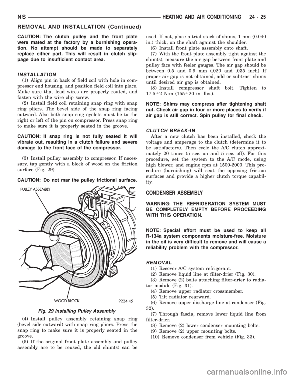
(3) Install pulley assembly to compressor. If neces-
sary, tap gently with a block of wood on the friction
surface (Fig. 29).
CAUTION: Do not mar the pulley frictional surface.
(4) Install pulley assembly retaining snap ring
(bevel side outward) with snap ring pliers. Press the
snap ring to make sure it is properly seated in the
groove.
(5) If the original front plate assembly and pulley
assembly are to be reused, the old shim(s) can beused. If not, place a trial stack of shims, 1 mm (0.040
in.) thick, on the shaft against the shoulder.
(6) Install front plate assembly onto shaft.
(7) With the front plate assembly tight against the
shim(s), measure the air gap between front plate and
pulley face with feeler gauges. The air gap should be
between 0.5 and 0.9 mm (.020 and .035 inch) If
proper air gap is not obtained, add or subtract shims
until desired air gap is obtained.
(8) Install compressor shaft bolt. Tighten to
17.562 N´m (155620 in. lbs.).
NOTE: Shims may compress after tightening shaft
nut. Check air gap in four or more places to verify if
air gap is still correct. Spin pulley for final check.
CLUTCH BREAK-IN
After a new clutch has been installed, check the
voltage and amperage to the clutch (determine it to
be satisfactory). Then cycle the A/C clutch approxi-
mately 20 times (5 sec. on and 5 sec. off). For this
procedure, set the system to the A/C mode, using
high blower, and engine rpm at 1500-2000. This pro-
cedure (burnishing) will seat the opposing friction
surfaces and provide a higher clutch torque capabil-
ity.
CONDENSER ASSEMBLY
WARNING: THE REFRIGERATION SYSTEM MUST
BE COMPLETELY EMPTY BEFORE PROCEEDING
WITH THIS OPERATION.
NOTE: Special effort must be used to keep all
R-134a system components moisture-free. Moisture
in the oil is very difficult to remove and will cause a
reliability problem with the compressor.
REMOVAL
(1) Recover A/C system refrigerant.
(2) Remove liquid line at filter-drier (Fig. 30).
(3) Remove (2) bolts attaching filter-drier to radia-
tor module (Fig. 31).
(4) Remove upper radiator crossmember.
(5) Tilt radiator rearward.
(6) Remove upper discharge line at condenser (Fig.
32).
(7) Through fascia, remove lower liquid line from
filter-drier.
(8) Remove (2) lower condenser mounting bolts.
(9) Remove (2) upper mounting bolts.
(10) Remove condenser from vehicle (Fig. 33).
Fig. 29 Installing Pulley Assembly
NSHEATING AND AIR CONDITIONING 24 - 25
REMOVAL AND INSTALLATION (Continued)
Page 1848 of 1938
CAUTION: When removing hoses from heater core
inlet or outlet nipples, do not use excessive force.
Heater core may become damaged and leak engine
coolant.
(3) Carefully rotate hose back and forth while tug-
ging slightly away from connector nipple. If the hose
will not come off, slice the hose at the connector nip-
ple and peel off heater hose. This method will require
heater hose replacement.
INSTALLATION
For installation, reverse the above procedures.
LIQUID LINE
REMOVAL
(1) Disconnect the battery negative cable.
(2) Recover A/C system refrigerant.
(3) Remove the accessory drive belt.
(4) Remove upper generator bracket.
(5) Remove ground wire at dash panel.
(6) Remove the nut retaining the refrigerant line
sealing plate to the expansion valve (Fig. 39).
(7) Remove the stud from the expansion valve (Fig.
40).
(8) Remove liquid line from expansion valve.
(9) Cover the openings to prevent contamination.
(10) Disconnect wire connector at pressure trans-
ducer.
(11) Remove liquid line mounting bracket at right
frame rail.
(12) Using access slot between radiator crossmem-
ber and grille, loosen liquid line mounting plate at
filter-drier. Remove liquid line from filter-drier. It
may be necessary to bend liquid line in half to
remove line. The replacement line is a two-piece
assembly.
(13) Remove the old O-rings.
INSTALLATION
For installation, reverse the above procedures.
²Install the stud to the evaporator sealing plate
and tighten 7 to 11 N´m (64 to 96 in. lbs.) torque.
²Install new O-rings.
²Install two-piece line in place of original part.
²A
ssemble line halves after it is installed on vehicle.²Evacuate and recharge A/C system.
MODE DOOR ACTUATOR
REMOVAL
(1) Remove the lower left side steering column
cover. Refer to Group 8E, Instrument Panel and Sys-
tems.
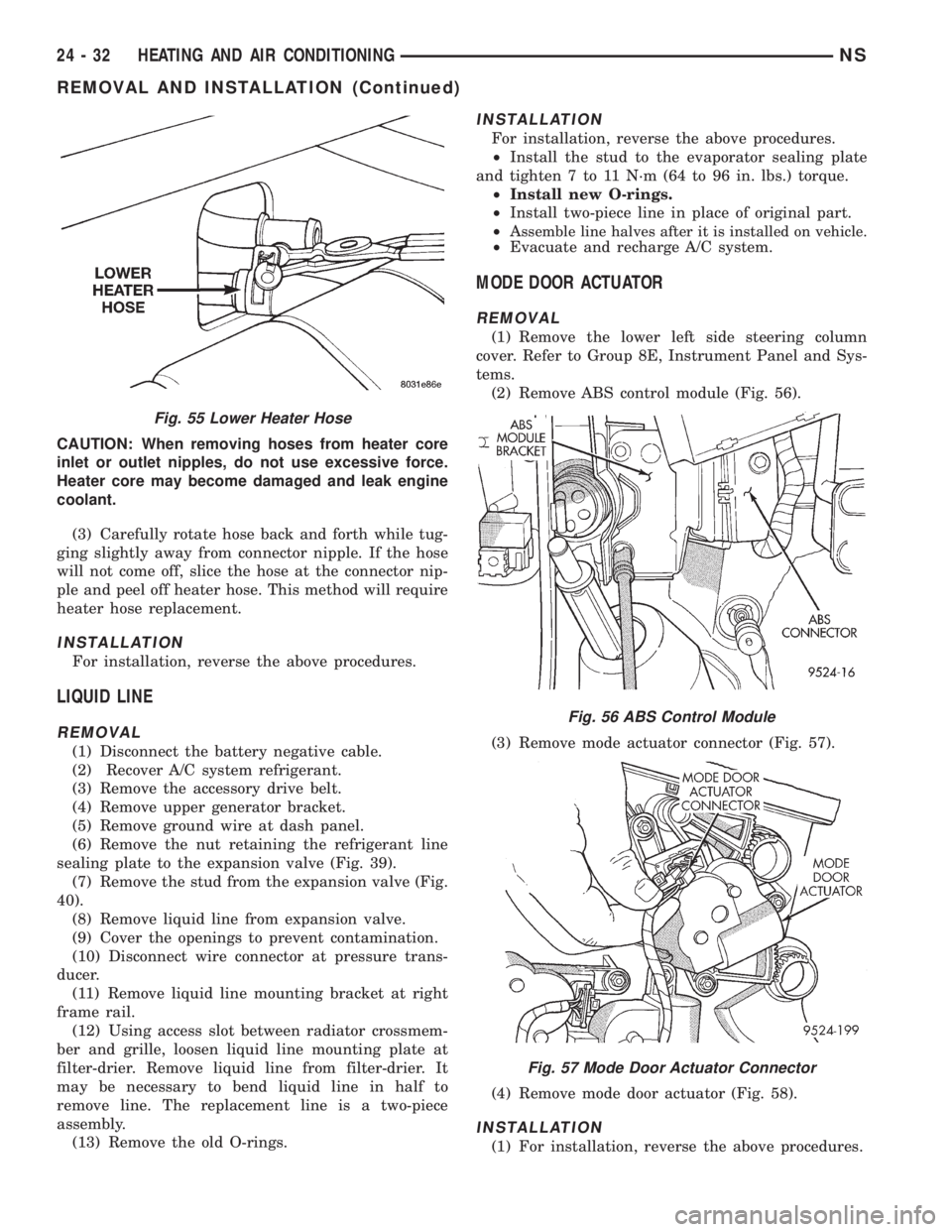
(2) Remove ABS control module (Fig. 56).
(3) Remove mode actuator connector (Fig. 57).
(4) Remove mode door actuator (Fig. 58).
INSTALLATION
(1) For installation, reverse the above procedures.
Fig. 55 Lower Heater Hose
Fig. 56 ABS Control Module
Fig. 57 Mode Door Actuator Connector
24 - 32 HEATING AND AIR CONDITIONINGNS
REMOVAL AND INSTALLATION (Continued)
Page 1849 of 1938
(2) Perform the HVAC control Calibration Diagnos-
tic and Cooldown test.
SIDE WINDOW DEMISTER DUCTS
LEFT SIDE
The LEFT side window demister duct is a two
piece design. The left side has a long duct that
attaches to an intermediate duct and then to the dis-
tribution housing. The duct is located on top of the
instrument panel. To service the duct, remove the I/P
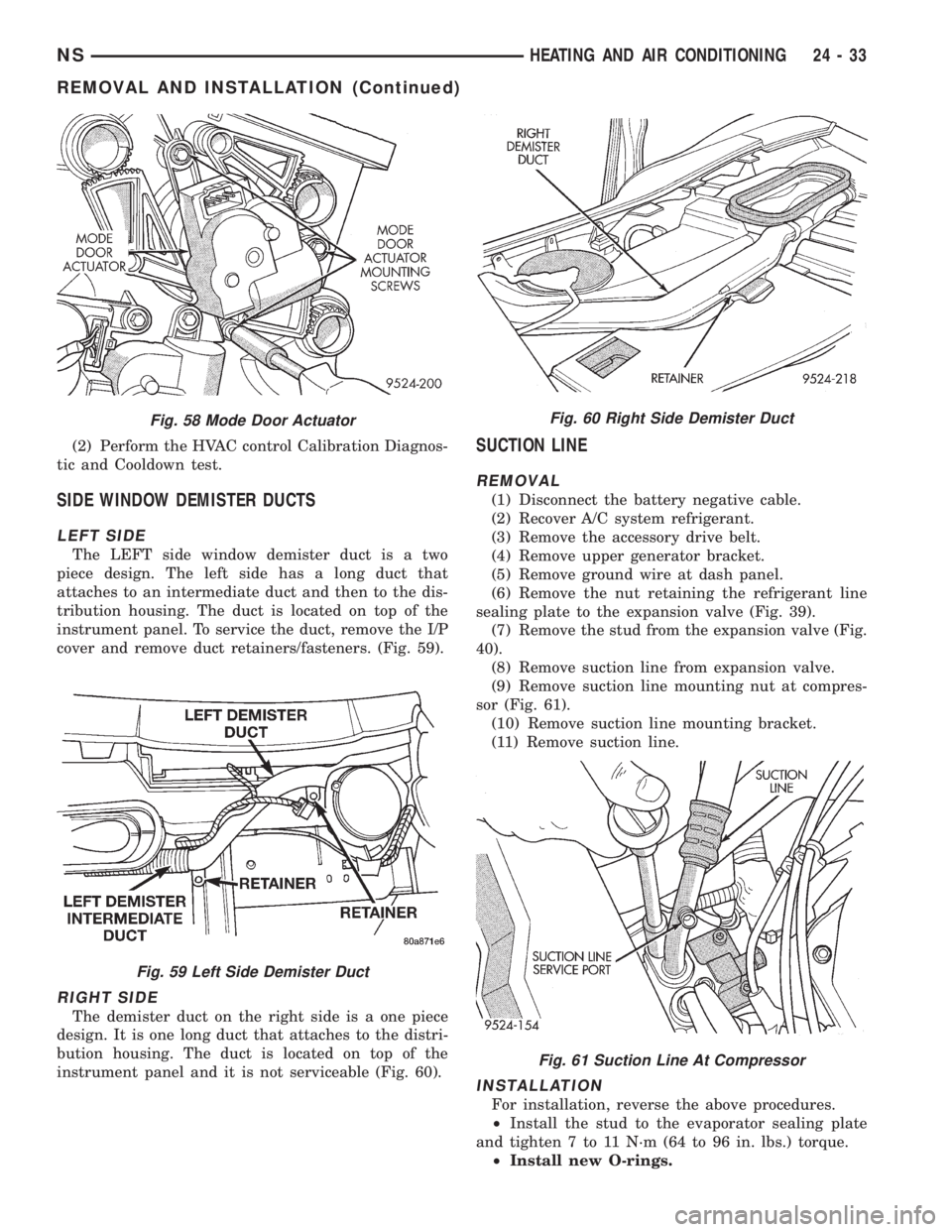
cover and remove duct retainers/fasteners. (Fig. 59).
RIGHT SIDE
The demister duct on the right side is a one piece
design. It is one long duct that attaches to the distri-
bution housing. The duct is located on top of the
instrument panel and it is not serviceable (Fig. 60).
SUCTION LINE
REMOVAL
(1) Disconnect the battery negative cable.
(2) Recover A/C system refrigerant.
(3) Remove the accessory drive belt.
(4) Remove upper generator bracket.
(5) Remove ground wire at dash panel.
(6) Remove the nut retaining the refrigerant line
sealing plate to the expansion valve (Fig. 39).
(7) Remove the stud from the expansion valve (Fig.
40).
(8) Remove suction line from expansion valve.
(9) Remove suction line mounting nut at compres-
sor (Fig. 61).
(10) Remove suction line mounting bracket.
(11) Remove suction line.
INSTALLATION
For installation, reverse the above procedures.
²Install the stud to the evaporator sealing plate
and tighten 7 to 11 N´m (64 to 96 in. lbs.) torque.
²Install new O-rings.
Fig. 58 Mode Door Actuator
Fig. 59 Left Side Demister Duct
Fig. 60 Right Side Demister Duct
Fig. 61 Suction Line At Compressor
NSHEATING AND AIR CONDITIONING 24 - 33
REMOVAL AND INSTALLATION (Continued)
Page 1865 of 1938

NOTE: If the heater core was emptied and was not
prefilled, it is necessary to thermal cycle the vehicle
TWICE. The heater core is positioned higher than
the radiator fill cap. Therefore the heater core will
not gravity fill to level. To thermal cycle the vehicle,
it must be operated till the thermostat opens, then
turned off and allowed to cool. In order to verify
that the auxiliary unit is filled completely, the follow-
ing procedure can be used:
²Vehicle at room temperature.
²Engine is brought up to operating temperature.
²Front unit is OFF, temperature slides are at full
HEAT position.
²Engine is at idle.
²With rear blower motor ON HIGH
²Discharge air temperature, measured at the
dual register located on the C-pillar base, is between
57ÉC to 62ÉC (135É and 145É F).
REAR HEATER LINES
REMOVAL
NOTE: Review Safety Precautions and Warnings
before proceeding with this operation.
(1) Partially drain engine cooling system. Refer to
Group 7, Engine Cooling.
(2) Loosen clamp at the front end of the hose
located at the right, outboard side of the underbody,
rearward of the front crossmember. (Fig. 2)
(3) Carefully rotate hose back and forth while tug-
ging slightly away from connector nipple. If the hose
will not come off, slice the hose at the connector nip-
ple and peel off heater hose. This method will require
heater hose replacement.
CAUTION: When removing hoses from outlet nip-
ples, do not use excessive force. Outlet nipples
may become damaged and leak engine coolant.
(4) Compress insert in rear heater hose quick con-
nection and pull downward on hose. (Fig. 4)(5) Remove (3) straps securing underbody lines.
(Fig. 1)
(6) Separate and remove rear heater lines from
vehicle.
INSTALLATION
For installation, reverse the above procedures.
MODE DOOR
REMOVAL
(1) Remove A/C unit.
(2) Place unit on bench.
(3) Remove heater core.
(4) Remove blower scroll.
(5) Remove evaporator cover.
(6) Remove A/C line to expansion valve mounting
nut.
(7) Carefully pull evaporator out of housing.
(8) Remove mode door actuator and gear exten-
sion.
(9) Remove Heater-A/C housing clips and screws.
(10) Separate housing halves.
(11) Remove mode door.
INSTALLATION
For installation, reverse the above procedures.
MODE DOOR ACTUATOR
REMOVAL
(1) Remove A/C unit.
(2) Place unit on bench.
(3) Remove mode door actuator connector.
(4) Remove mode door actuator mounting screws
and remove actuator.
INSTALLATION
For installation, reverse the above procedures.
NSHEATING AND AIR CONDITIONING 24 - 49
REMOVAL AND INSTALLATION (Continued)
Page 1867 of 1938
HEATING AND AIR CONDITIONING
CONTENTS
page page
GENERAL INFORMATION
INTRODUCTION........................ 1
SAFETY PRECAUTIONS AND WARNINGS.... 2
DESCRIPTION AND OPERATION
A/C PRESSURE TRANSDUCER............ 2
A/C SERVICE PORTS.................... 2
AIR DISTRIBUTION DUCTS............... 2
COMPRESSOR......................... 2
COMPRESSOR HIGH-PRESSURE RELIEF
VALVE .............................. 3
CONDENSATE DRAIN.................... 3
ENGINE COOLING SYSTEM REQUIREMENTS . 3
EVAPORATOR PROBE................... 3
HANDLING TUBING AND FITTINGS........ 3
HVAC CONTROL MODULE................ 3
SIDE DOOR HEATER A/C OUTLETS........ 4
SIDE WINDOW DEMISTER............... 4
SYSTEM AIRFLOW..................... 4
SYSTEM OIL LEVEL..................... 4
DIAGNOSIS AND TESTING
A/C PERFORMANCE TEST............... 11
A/C PRESSURE TRANSDUCER........... 11
ACTUATOR CALIBRATION/DIAGNOSTICS AND
COOLDOWN TEST..................... 5
BLOWER MOTOR AND WHEEL ASSEMBLY . 12
COMPRESSOR CLUTCH/COIL............ 12
COMPRESSOR NOISE DIAGNOSIS........ 12
EXPANSION VALVE.................... 14
HEATER PERFORMANCE TEST........... 14
HVAC CONTROL DIAGNOSTIC CONDITIONS . 9
SYSTEM CHARGE LEVEL TEST........... 15SERVICE PROCEDURES
CHARGING REFRIGERANT SYSTEM....... 17
EVACUATING REFRIGERANT SYSTEM..... 17
R-134a REFRIGERANT.................. 16
STICKING HVAC CONTROL MODULE PUSH
BUTTONS.......................... 18
SYSTEM LEAK CHECKING............... 19
THERMOCOUPLE PROBE............... 18
REMOVAL AND INSTALLATION
A/C PRESSURE TRANSDUCER........... 19
A/C SERVICE PORTS................... 19
BLEND-AIR DOOR ACTUATOR........... 20
BLOWER MOTOR AND WHEEL ASSEMBLY . 20
BLOWER MOTOR RESISTOR BLOCK...... 21
BLOWER MOTOR WHEEL............... 22
COMPRESSOR (2.5L TURBO DIESEL)..... 22
CONDENSER ASSEMBLY................ 23
DISCHARGE LINE..................... 23
EVAPORATOR PROBE.................. 24
EXPANSION VALVE.................... 25
FILTER-DRIER ASSEMBLY............... 26
HEATER A/C UNIT HOUSING............. 26
HEATER CORE........................ 26
HEATER HOSES....................... 28
LIQUID LINE......................... 28
MODE DOOR ACTUATOR................ 29
RECIRC DOOR ACTUATOR.............. 30
SIDE WINDOW DEMISTER DUCTS........ 29
SUCTION LINE........................ 29
DISASSEMBLY AND ASSEMBLY
HEATER A/C UNIT RECONDITION......... 30
GENERAL INFORMATION
INTRODUCTION
The Heater, or Heater and Air Conditioning sys-
tems share many of the same components. This
group will deal with both systems together when
component function is common, and separately when
they are not.
For proper operation of the instrument panel con-
trols, refer to the Owner's Manual provided with the
vehicle.All vehicles are equipped with a common Heater
A/C unit housing assembly. When the vehicle has
only a heater system, the evaporator and recirculat-
ing air door are omitted.
An optional zone control HVAC unit is available.
This unit has dual blend-air doors that can be regu-
lated independently of each other. The temperature
setting can be different from driver's side to passen-
ger side.
NS/GSHEATING AND AIR CONDITIONING 24 - 1
Page 1869 of 1938
pressor is driven off the back of the power steering
pump. A rubber flex coupling transfers the power from
the power steering pump to the compressor clutch.
COMPRESSOR HIGH-PRESSURE RELIEF VALVE
The High Pressure Relief Valve prevents damage
to the air conditioning system if excessive pressure
develops. Excessive pressure can be caused by con-
denser air flow blockage, refrigerant overcharge, or
air and moisture in the system.
The high pressure relief valve vents only a small
amount of refrigerant necessary to reduce system
pressure and then reseats itself. The majority of the
refrigerant is conserved in the system. The valve is
calibrated to vent at a pressure of 3450 to 4140 kPa
(500 to 600 psi). If a valve has vented a small
amount of refrigerant, it does not necessarily mean
the valve is defective.
The High Pressure Relief Valve is located on the
compressor manifold at the discharge passage.
NOTE: Special effort must be used to keep all
R-134a system components moisture-free. Moisture
in the oil is very difficult to remove and will cause a
reliability problem with the compressor.
CONDENSATE DRAIN
Condensation from the evaporator housing is
drained through the dash panel and on to the
ground. This drain must be kept open to prevent
water from collecting in the bottom of the housing.
If the drain is blocked condensate cannot drain,
causing water to back up and spill into the passenger
compartment. It is normal to see condensate drain-
age below the vehicle.
ENGINE COOLING SYSTEM REQUIREMENTS
To maintain ample temperature levels from the
heating-A/C system, the cooling system must be in
proper working order. Refer to Group 0, Lubrication
and Maintenance or Group 7, Cooling System of this
manual.
The use of a bug screen is not recommended. Any
obstructions forward of the condenser can reduce the
effectiveness of the air conditioning system.
EVAPORATOR PROBE
The Evaporator probe is located on the HVAC. The
probe prevents evaporator freeze-up by signaling the
Powertrain Control Module to cycle the compressor
ON and OFF. The probe monitors the temperature of
the refrigerant after expansion.
The evaporator probe is inserted into the evapora-
tor between the coils. The probe is a sealed unit and
cannot be adjusted or repaired. It must be replaced if
found defective.
HANDLING TUBING AND FITTINGS
Kinks in the refrigerant tubing or sharp bends in
the refrigerant hose lines will greatly reduce the
capacity of the entire system. High pressures are pro-
duced in the system when it is operating. Extreme
care must be exercised to make sure that all connec-
tions are pressure tight. Dirt and moisture can enter
the system when it is opened for repair or replace-
ment of lines or components. The refrigerant oil will
absorb moisture readily out of the air. This moisture
will convert into acids within a closed system.
CAUTION: The system must be completely empty
before opening any fitting or connection in the
refrigeration system. Open fittings with caution
even after the system has been emptied. If any
pressure is noticed as a fitting is loosened,
retighten fitting and evacuate the system again.
A good rule for the flexible hose lines is to keep
the radius of all bends at least 10 times the diame-
ter of the hose. Sharper bends will reduce the flow
of refrigerant. The flexible hose lines should be
routed so they are at least 3 inches (80 mm) from
the exhaust manifold. Inspect all flexible hose lines
to make sure they are in good condition and prop-
erly routed.
The use of correct wrenches when making con-
nections is very important. Improper wrenches or
improper use of wrenches can damage the fittings.
The internal parts of the A/C system will remain
stable as long as moisture-free refrigerant and
refrigerant oil is used. Abnormal amounts of dirt,
moisture or air can upset the chemical stability.
This may cause operational troubles or even seri-
ous damage if present in more than very small
quantities.
When opening a refrigeration system, have every-
thing you will need to repair the system ready. This
will minimize the amount of time the system must
be opened. Cap or plug all lines and fittings as
soon as they are opened. This will help prevent the
entrance of dirt and moisture. All new lines and
components should be capped or sealed until they
are ready to be used.
All tools, including the refrigerant dispensing
manifold, the manifold gauge set, and test hoses
should be kept clean and dry.
HVAC CONTROL MODULE
The HVAC control module regulates the operation
of the various actuator motors. The actuator motors
are used to move the mode, blend- air, and recirc.
doors (Fig. 2).
The control module is included in the A/C control
head located on the instrument panel. The control
head includes the blower speed switch, rear wiper
NS/GSHEATING AND AIR CONDITIONING 24 - 3
DESCRIPTION AND OPERATION (Continued)
Page 1871 of 1938
capacity of the system and consequently result in
higher discharge air temperatures.
NOTE: The oil used in the Denso 2.5L Turbo Diesel
and the Denso 2.0L gasoline engine compressors is
ND-8 PAG R134a refrigerant oil. Only refrigerant oil
of the same type should be used to service the sys-
tem. Do not use any other oil. The oil container
should be kept tightly capped until it is ready for
use. Tightly cap afterwards to prevent contamina-
tion from dirt and moisture. Refrigerant oil will
quickly absorb any moisture it comes in contact
with. Special effort must be used to keep all R-134a
system components moisture-free. Moisture in the
oil is very difficult to remove and will cause a reli-
ability problem with the compressor.
It will not be necessary to check oil level in the
compressor or to add oil unless there has been an oil
loss. Oil loss at a leak point will be evident by the
presence of a wet, shiny surface around the leak.
REFRIGERANT OIL LEVEL CHECK
When an air conditioning system is first assem-
bled, all components (except the compressor) are
refrigerant oil free. After the system has been
charged with R134a refrigerant and operated, the oil
in the compressor is dispersed through the lines and
components. The evaporator, condenser, and filter-
drier will retain a significant amount of oil, refer to
the Refrigerant Oil Capacities chart. When a compo-
nent is replaced, the specified amount of refrigerant
oil must be added. When the compressor is replaced,
the amount of oil that is retained in the rest of the
system must be drained from the replacement com-
pressor. When a line or component has ruptured and
oil has escaped, the compressor should be removed
and drained. The compressor is drained through the
suction port or by removing the sump bolt on top of
the compressor, refer to Compressor Removal and
Installation procedures. The filter-drier must be
replaced along with the ruptured part. The oil capac-
ity of the system, minus the amount of oil still in the
remaining components, can be measured and poured
into the suction port of the compressor.
Example: The evaporator retains 50 ml (1.7 oz.).
The condenser retains 30 ml (1 oz) of oil, and system
capacity may be 220 ml (7.40 oz) of oil.
220 ml minus 90 ml = 130 ml (4.40 oz.).
CAUTION: The refrigerant oil used in a R-134a A/C
system is unique. Use only oils which were designed
to work with R-134a refrigerant. The oil designated
for the Denso 2.5L Turbo Diesel and Denso 2.0L gas-
oline engine compressors is ND-8 PAG compressor
oil. For gasoline vehicles still using R-12 refrigerant,
use ND8 PAG compressor oil.
SERVICING REFRIGERANT OIL LEVEL
(1) Using a refrigerant recovery machine, remove
refrigerant from the A/C system.
(2) Remove refrigerant lines from A/C compressor.
(3) Remove compressor from vehicle.
(4) From suction port on top of compressor, drain
refrigerant oil from compressor.
(5) Add system capacity minus the capacity of
components that have not been replaced through suc-
tion port on compressor. Refer to the Refrigerant Oil
Capacity Chart.
(6) Install compressor, connect refrigerant lines,
evacuate, and charge refrigerant system.
DIAGNOSIS AND TESTING
ACTUATOR CALIBRATION/DIAGNOSTICS AND
COOLDOWN TEST
GENERAL INFORMATION
If the HVAC control module is replaced, the Cali-
bration Diagnostic and Cooldown tests will need to
be performed. Once this group of tests have success-
fully passed, they can be performed individually. The
engine must be running during the test to provide
hot coolant for the heater, A/C compressor operation
and to assure that the actuators are calibrated cor-
rectly. The HVAC control module is capable of trou-
bleshooting the system in approximately 120 seconds.
If a condition is detected, an error code is displayed.
The error code cannot be erased until the condition is
repaired and the diagnostic test is performed. Check
wire before replacing components, refer to Group 8W,
Wiring Diagrams.
CAUTION: Do not remove the actuators from the
Heater-A/C unit assembly with power applied.
Removal should only be done with the Ignition OFF.
The actuators have no mechanical stops to limit the
travel. If the actuator rotates and is not connected to
the unit assembly, it will become out of calibration.
ACTUATOR CALIBRATION
Mode, Blend and Zone (if equipped) door calibra-
tion compensates for mechanical variations in the
REFRIGERANT OIL CAPACITIES
REFRIGERANT OIL CAPACITIES
COMPONENT ML OZ
Compressor 135 ml 4.5 oz
Filter-Drier 30 ml 1.0 oz
Condenser 30 ml 1.0 oz
Evaporator 50 ml 1.7 oz
NS/GSHEATING AND AIR CONDITIONING 24 - 5
DESCRIPTION AND OPERATION (Continued)
Page 1872 of 1938
actuators, HVAC control module and its linkages. In-
vehicle calibration can be entered from the control's
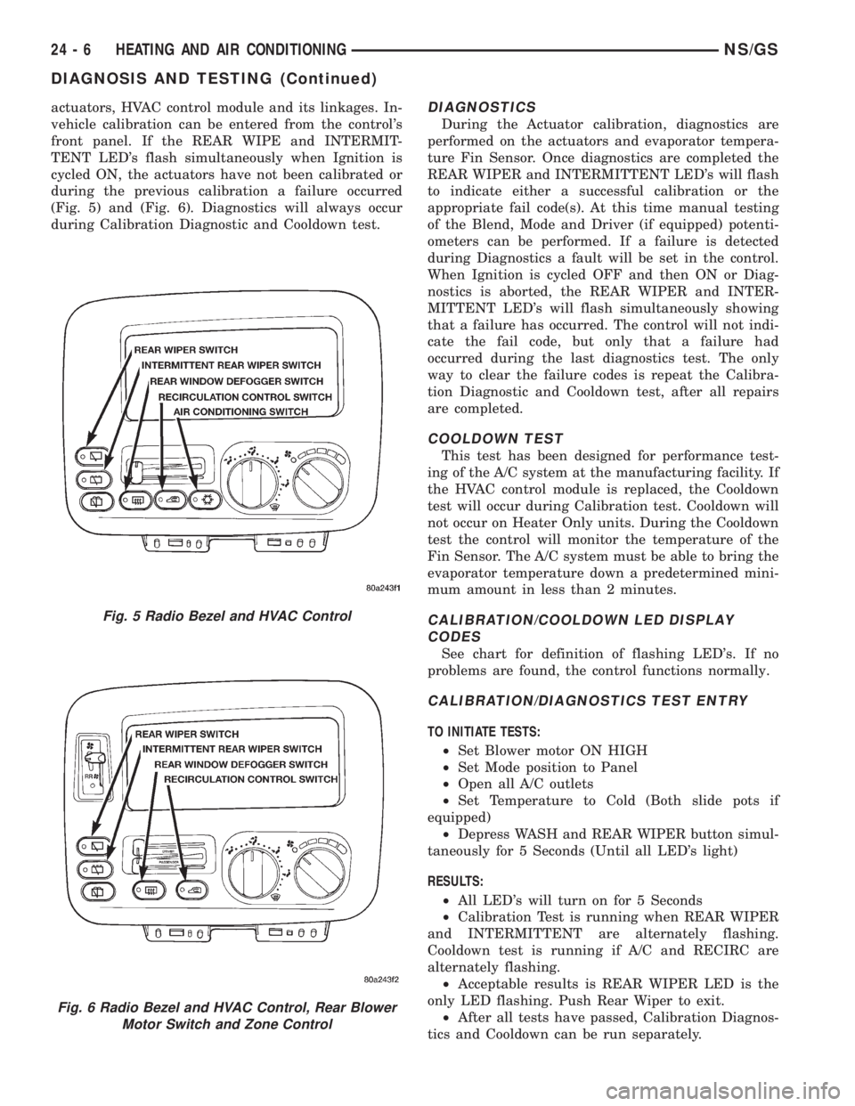
front panel. If the REAR WIPE and INTERMIT-
TENT LED's flash simultaneously when Ignition is
cycled ON, the actuators have not been calibrated or
during the previous calibration a failure occurred
(Fig. 5) and (Fig. 6). Diagnostics will always occur
during Calibration Diagnostic and Cooldown test.DIAGNOSTICS
During the Actuator calibration, diagnostics are
performed on the actuators and evaporator tempera-
ture Fin Sensor. Once diagnostics are completed the
REAR WIPER and INTERMITTENT LED's will flash
to indicate either a successful calibration or the
appropriate fail code(s). At this time manual testing
of the Blend, Mode and Driver (if equipped) potenti-
ometers can be performed. If a failure is detected
during Diagnostics a fault will be set in the control.
When Ignition is cycled OFF and then ON or Diag-
nostics is aborted, the REAR WIPER and INTER-
MITTENT LED's will flash simultaneously showing
that a failure has occurred. The control will not indi-
cate the fail code, but only that a failure had
occurred during the last diagnostics test. The only
way to clear the failure codes is repeat the Calibra-
tion Diagnostic and Cooldown test, after all repairs
are completed.
COOLDOWN TEST
This test has been designed for performance test-
ing of the A/C system at the manufacturing facility. If
the HVAC control module is replaced, the Cooldown
test will occur during Calibration test. Cooldown will
not occur on Heater Only units. During the Cooldown
test the control will monitor the temperature of the
Fin Sensor. The A/C system must be able to bring the
evaporator temperature down a predetermined mini-
mum amount in less than 2 minutes.
CALIBRATION/COOLDOWN LED DISPLAY
CODES
See chart for definition of flashing LED's. If no
problems are found, the control functions normally.
CALIBRATION/DIAGNOSTICS TEST ENTRY
TO INITIATE TESTS:
²Set Blower motor ON HIGH
²Set Mode position to Panel
²Open all A/C outlets
²Set Temperature to Cold (Both slide pots if
equipped)
²Depress WASH and REAR WIPER button simul-
taneously for 5 Seconds (Until all LED's light)
RESULTS:
²All LED's will turn on for 5 Seconds
²Calibration Test is running when REAR WIPER
and INTERMITTENT are alternately flashing.
Cooldown test is running if A/C and RECIRC are
alternately flashing.
²Acceptable results is REAR WIPER LED is the
only LED flashing. Push Rear Wiper to exit.
²After all tests have passed, Calibration Diagnos-
tics and Cooldown can be run separately.
Fig. 5 Radio Bezel and HVAC Control
Fig. 6 Radio Bezel and HVAC Control, Rear Blower
Motor Switch and Zone Control
24 - 6 HEATING AND AIR CONDITIONINGNS/GS
DIAGNOSIS AND TESTING (Continued)