1996 CHRYSLER VOYAGER oil level
[x] Cancel search: oil levelPage 1076 of 1938
ENGINE ASSEMBLY
REMOVAL
(1) Perform fuel pressure release procedure. Refer
to Group 14, Fuel System for procedure. Remove fuel
line to fuel rail.
(2) Disconnect battery.
(3) Remove Air cleaner and hoses.
(4) Drain cooling system. Refer to Group 7, Cooling
System for procedure.
(5) Remove upper radiator hose and remove radia-
tor fans. Refer to Group 7, Cooling System for proce-
dure.
(6) Remove lower radiator hose.
(7) Disconnect automatic transmission cooler lines
and plug, if equipped.
(8) Disconnect transmission shift linkage.
(9) Disconnect throttle body linkage.
(10) Disconnect engine wiring harness.
(11) Disconnect heater hoses.
(12) Discharge Air Conditioning System. Refer to
Group 24, Air Conditioning for procedure.
(13) Hoist vehicle and remove right inner splash
shield. Remove wheels and tires.
(14) Loosen power steering belt for pump removal.
Refer to Group 7, Cooling System for procedure.
(15) Remove axle shafts. Refer to Group 2, Suspen-
sion and Driveshafts for procedure.
(16) Disconnect exhaust pipe from manifold.
(17) Remove front and rear engine mount brackets
from the body.
(18) Remove bending braces and front engine
mount bracket. Remove transmission inspection
cover.
(19) Mark flexplate to torque converter and
remove torque converter bolts.
(20) Install front engine mount bracket.
(21) Lower vehicle.
(22) Remove power steering pump. Set pump
aside.
(23) Remove A/C lines at compressor and cap.
(24) Remove ground straps to body.
(25) Raise vehicle enough to allow engine dolly
Special Tool 6135, cradle Special Tool 6710 with
Posts Special Tool 6848 and Adaptor Special Tool
8130 to be installed under vehicle (Fig. 27).
(26) Loosen cradle posts to allow movement for
proper positioning. Locate two rear posts (right side
of engine) into the holes on the engine bedplate.
Locate the two front posts (left side of engine) on the
front engine bracket and A/C compressor bracket
(Fig. 27). Lower vehicle and position cradle mounts
until the engine is resting on mounts. Tighten
mounts to cradle frame. This will keep mounts from
moving when removing or installing engine and
transmission.(27) Lower vehicle so the weight ofONLY THE
ENGINE AND TRANSMISSIONare on the cradle.
(28) Remove engine and transmission mount bolts.
(29) Raise vehicle slowly. It may be necessary to
move the engine/transmission assembly on the cradle
to allow for removal around the body.
INSTALLATION
(1) Position engine and transmission assembly
under vehicle and slowly lower the vehicle over the
engine and transmission.
(2) Align engine and transmission mounts to
attaching points. Install mounting bolts at the right
engine and left transmission mounts. Refer to proce-
dures outlined in this section.
(3) Slowly raise vehicle enough to remove the
engine dolly and cradle Special Tools 6135 and 6710.
(4) Install axle shafts. Refer to Group 2, Suspen-
sion and Driveshafts for procedure.
(5) Install transmission and engine braces and
splash shields.
(6) Connect exhaust system to manifold. Refer to
Group 11, Exhaust System and Intake Manifold for
procedure and torque specifications.
(7) Install power steering pump. Refer to Cooling
System Group 7, Accessory Drive Section for belt ten-
sion adjustment.
(8) Install A/C compressor hoses. Refer to Group
24, Heater and Air Conditioning for procedure.
(9) Install accessory drive belts. Refer to Group 7,
Cooling System Accessory Drive Section for belt ten-
sion adjustment.
(10) Install front and rear engine mounts. Refer to
this section for procedure.
(11) Install inner splash shield. Install wheels and
tires.
(12) Connect automatic transmission cooler lines,
and shift linkage. Refer to Group 21, Transmission
for procedures.
(13) Connect fuel line and heater hoses.
(14) Install ground straps. Connect engine and
throttle body connections and harnesses. Refer to
Group 8, Electrical for procedure.
(15) Connect throttle body linkage. Refer to Group
14, Fuel System for procedure.
(16) Install radiator fans. Install radiator hoses.
Fill cooling system. Refer to Group 7, Cooling System
for filling procedure.
(17) Connect battery.
(18) Install air cleaner and hoses.
(19) Install oil filter. Fill engine crankcase with
proper oil to correct level.
(20) Start engine and run until operating temper-
ature is reached.
(21) Adjust transmission linkage, if necessary.
9 - 26 2.4L ENGINENS
REMOVAL AND INSTALLATION (Continued)
Page 1095 of 1938
OIL PAN
REMOVAL
(1) Raise vehicle on hoist and drain engine oil.
(2) Remove front engine mount bracket from
engine and insulator mount.
(3) Remove bolts attaching bending strut to engine
and transaxle.
(4) Remove bolts attaching collar and bending
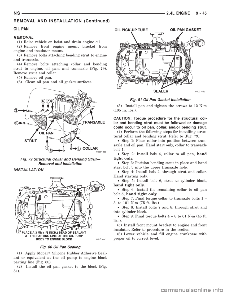
strut to engine, oil pan, and transaxle (Fig. 79).
Remove strut and collar.
(5) Remove oil pan.
(6) Clean oil pan and all gasket surfaces.
INSTALLATION
(1) Apply MopartSilicone Rubber Adhesive Seal-
ant or equivalent at the oil pump to engine block
parting line (Fig. 80).
(2) Install the oil pan gasket to the block (Fig.
81).(3) Install pan and tighten the screws to 12 N´m
(105 in. lbs.).
CAUTION: Torque procedure for the structural col-
lar and bending strut must be followed or damage
could occur to oil pan, collar, and/or bending strut.
(4) Perform the following steps for installing struc-
tural collar and bending strut. Refer to (Fig. 79):
²Step 1: Place collar into position between tran-
saxle and oil pan. Hand start only, collar to transaxle
bolt 1.
²Step 2: Install bolt 4, collar to oil pan,hand
tight only.
²Step 3: Position bending strut in place and hand
start bolt 3 into the upper transaxle hole.
²Step 4: Install bolt 2, through strut and collar.
Hand starting only.
²Step 5: Install bolt 6, strut to cylinder block,
hand tight only.
²Step 6: Install the remaining collar to oil pan
bolt 5,hand tight only.
²Step 7: Final torque collar to transaxle bolts 1 ±
3, to 101 N´m (75 ft. lbs.)
²Step 8: Install bolts 7 and 8, through strut and
into cylinder block.
²Step 9: Final torque bolts4±8to61N´m(45ft.
lbs.).
(5) Install front mount bracket to engine and front
insulator. Refer to procedure in the section.
(6) Lower vehicle and fill engine crankcase with
proper oil to correct level.
Fig. 79 Structural Collar and Bending StrutÐ
Removal and Installation
Fig. 80 Oil Pan Sealing
Fig. 81 Oil Pan Gasket Installation
NS2.4L ENGINE 9 - 45
REMOVAL AND INSTALLATION (Continued)
Page 1111 of 1938
3.0L ENGINE
INDEX
page page
DESCRIPTION AND OPERATION
ENGINE COMPONENTS.................. 61
ENGINE IDENTIFICATION NUMBER......... 61
ENGINE LUBRICATION................... 61
DIAGNOSIS AND TESTING
CHECKING ENGINE OIL PRESSURE......... 62
SERVICE PROCEDURES
AUTO LASH ADJUSTER................... 62
CHECKING CRANKSHAFT END PLAY........ 65
FITTING CONNECTING ROD BEARINGS...... 63
FITTING MAIN BEARING.................. 63
VALVE SERVICE RECONDITION............ 66
REMOVAL AND INSTALLATION
CAMSHAFT SEAL....................... 72
CAMSHAFT............................ 71
CRANKSHAFT.......................... 81
CYLINDER HEAD COVER................. 70
CYLINDER HEAD........................ 73
ENGINE ASSEMBLY...................... 69
ENGINE MOUNTS....................... 68
FRONT CRANKSHAFT OIL SEAL............ 83OIL FILTER AND ADAPTOR................ 84
OILPAN ............................... 77
OIL PUMP............................. 84
PISTON AND CONNECTING ROD........... 78
REAR CRANKSHAFT SEAL................ 83
ROCKER ARMS......................... 72
TIMING BELT........................... 75
DISASSEMBLY AND ASSEMBLY
ROCKER ARMS AND SHAFTS.............. 85
CLEANING AND INSPECTION
CYLINDER BORE........................ 87
CYLINDER HEAD........................ 86
OIL PUMP............................. 87
TIMING BELT........................... 86
ADJUSTMENTS
ENGINE MOUNTS....................... 88
SPECIFICATIONS
3.0L ENGINE........................... 89
TORQUE CHART 3.0L.................... 90
SPECIAL TOOLS
3.0L ENGINE........................... 91
DESCRIPTION AND OPERATION
ENGINE IDENTIFICATION NUMBER
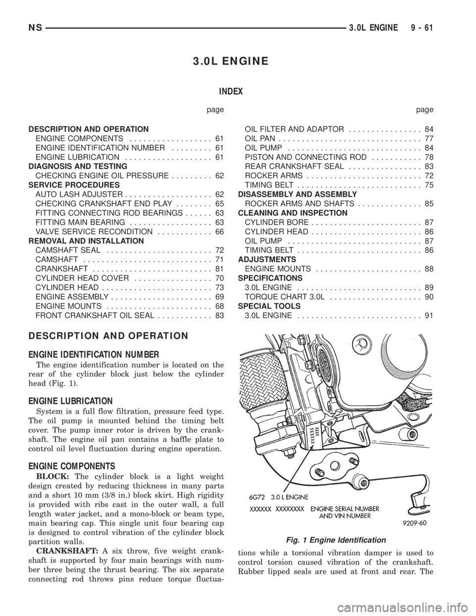
The engine identification number is located on the
rear of the cylinder block just below the cylinder
head (Fig. 1).
ENGINE LUBRICATION
System is a full flow filtration, pressure feed type.
The oil pump is mounted behind the timing belt
cover. The pump inner rotor is driven by the crank-
shaft. The engine oil pan contains a baffle plate to
control oil level fluctuation during engine operation.
ENGINE COMPONENTS
BLOCK:The cylinder block is a light weight
design created by reducing thickness in many parts
and a short 10 mm (3/8 in.) block skirt. High rigidity
is provided with ribs cast in the outer wall, a full
length water jacket, and a mono-block or beam type,
main bearing cap. This single unit four bearing cap
is designed to control vibration of the cylinder block
partition walls.
CRANKSHAFT:A six throw, five weight crank-
shaft is supported by four main bearings with num-
ber three being the thrust bearing. The six separate
connecting rod throws pins reduce torque fluctua-tions while a torsional vibration damper is used to
control torsion caused vibration of the crankshaft.
Rubber lipped seals are used at front and rear. The
Fig. 1 Engine Identification
NS3.0L ENGINE 9 - 61
Page 1120 of 1938
(25) Remove ground straps to body.
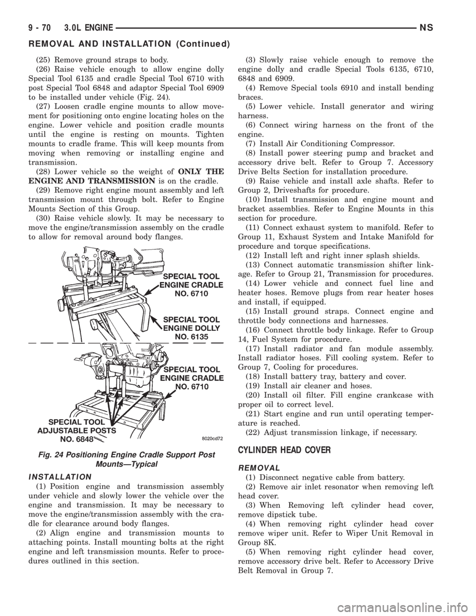
(26) Raise vehicle enough to allow engine dolly
Special Tool 6135 and cradle Special Tool 6710 with
post Special Tool 6848 and adaptor Special Tool 6909
to be installed under vehicle (Fig. 24).
(27) Loosen cradle engine mounts to allow move-
ment for positioning onto engine locating holes on the
engine. Lower vehicle and position cradle mounts
until the engine is resting on mounts. Tighten
mounts to cradle frame. This will keep mounts from
moving when removing or installing engine and
transmission.
(28) Lower vehicle so the weight ofONLY THE
ENGINE AND TRANSMISSIONis on the cradle.
(29) Remove right engine mount assembly and left
transmission mount through bolt. Refer to Engine
Mounts Section of this Group.
(30) Raise vehicle slowly. It may be necessary to
move the engine/transmission assembly on the cradle
to allow for removal around body flanges.
INSTALLATION
(1) Position engine and transmission assembly
under vehicle and slowly lower the vehicle over the
engine and transmission. It may be necessary to
move the engine/transmission assembly with the cra-
dle for clearance around body flanges.
(2) Align engine and transmission mounts to
attaching points. Install mounting bolts at the right
engine and left transmission mounts. Refer to proce-
dures outlined in this section.(3) Slowly raise vehicle enough to remove the
engine dolly and cradle Special Tools 6135, 6710,
6848 and 6909.
(4) Remove Special tools 6910 and install bending
braces.
(5) Lower vehicle. Install generator and wiring
harness.
(6) Connect wiring harness on the front of the
engine.
(7) Install Air Conditioning Compressor.
(8) Install power steering pump and bracket and
accessory drive belt. Refer to Group 7. Accessory
Drive Belts Section for installation procedure.
(9) Raise vehicle and install axle shafts. Refer to
Group 2, Driveshafts for procedure.
(10) Install transmission and engine mount and
bracket assemblies. Refer to Engine Mounts in this
section for procedure.
(11) Connect exhaust system to manifold. Refer to
Group 11, Exhaust System and Intake Manifold for
procedure and torque specifications.
(12) Install left and right inner splash shields.
(13) Connect automatic transmission shifter link-
age. Refer to Group 21, Transmission for procedures.
(14) Lower vehicle and connect fuel line and
heater hoses. Remove plugs from rear heater hoses
and install, if equipped.
(15) Install ground straps. Connect engine and
throttle body connections and harnesses.
(16) Connect throttle body linkage. Refer to Group
14, Fuel System for procedure.
(17) Install radiator and fan module assembly.
Install radiator hoses. Fill cooling system. Refer to
Group 7, Cooling for procedures.
(18) Install battery tray, battery and cover.
(19) Install air cleaner and hoses.
(20) Install oil filter. Fill engine crankcase with
proper oil to correct level.
(21) Start engine and run until operating temper-
ature is reached.
(22) Adjust transmission linkage, if necessary.
CYLINDER HEAD COVER
REMOVAL
(1) Disconnect negative cable from battery.
(2) Remove air inlet resonator when removing left
head cover.
(3) When Removing left cylinder head cover,
remove dipstick tube.
(4) When removing right cylinder head cover
remove wiper unit. Refer to Wiper Unit Removal in
Group 8K.
(5) When removing right cylinder head cover,
remove accessory drive belt. Refer to Accessory Drive
Belt Removal in Group 7.
Fig. 24 Positioning Engine Cradle Support Post
MountsÐTypical
9 - 70 3.0L ENGINENS
REMOVAL AND INSTALLATION (Continued)
Page 1137 of 1938
CAUTION: This is a combined total dimension of
stock removal from cylinder head if any and block
top surface.
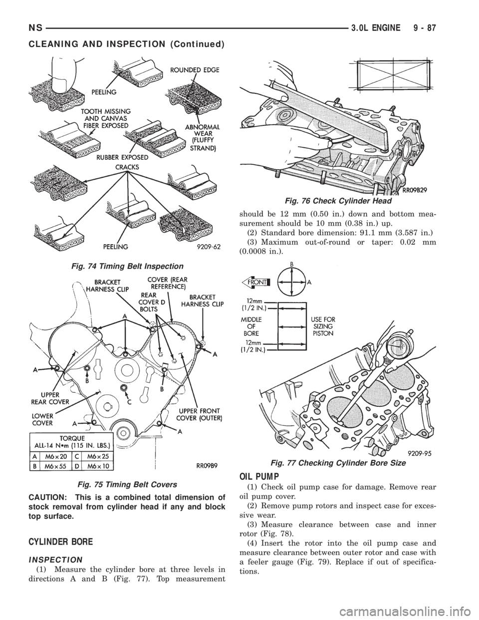
CYLINDER BORE
INSPECTION
(1) Measure the cylinder bore at three levels in
directions A and B (Fig. 77). Top measurementshould be 12 mm (0.50 in.) down and bottom mea-
surement should be 10 mm (0.38 in.) up.
(2) Standard bore dimension: 91.1 mm (3.587 in.)
(3) Maximum out-of-round or taper: 0.02 mm
(0.0008 in.).
OIL PUMP
(1) Check oil pump case for damage. Remove rear
oil pump cover.
(2) Remove pump rotors and inspect case for exces-
sive wear.
(3) Measure clearance between case and inner
rotor (Fig. 78).
(4) Insert the rotor into the oil pump case and
measure clearance between outer rotor and case with
a feeler gauge (Fig. 79). Replace if out of specifica-
tions.
Fig. 74 Timing Belt Inspection
Fig. 75 Timing Belt Covers
Fig. 76 Check Cylinder Head
Fig. 77 Checking Cylinder Bore Size
NS3.0L ENGINE 9 - 87
CLEANING AND INSPECTION (Continued)
Page 1144 of 1938
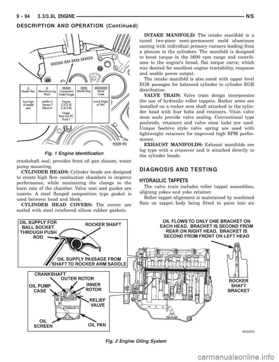
crankshaft seal, provides front oil pan closure, water
pump mounting.
CYLINDER HEADS:Cylinder heads are designed
to create high flow combustion chambers to improve
performance, while minimizing the change to the
burn rate of the chamber. Valve seat and guides are
inserts. A steel flanged composition type gasket is
used between head and block.
CYLINDER HEAD COVERS:The covers are
sealed with steel reinforced silicon rubber gaskets.INTAKE MANIFOLD:The intake manifold is a
tuned two-piece semi-permanent mold aluminum
casting with individual primary runners leading from
a plenum to the cylinders. The manifold is designed
to boost torque in the 3600 rpm range and contrib-
utes to the engine's broad, flat torque curve, which
was desired for excellent engine tractability, response
and usable power output.
The intake manifold is also cored with upper level
EGR passages for balanced cylinder to cylinder EGR
distribution.
VALVE TRAIN:Valve train design incorporates
the use of hydraulic roller tappets. Rocker arms are
installed on a rocker arm shaft attached to the cylin-
der head with four bolts and retainers. Viton valve
stem seals provide valve sealing. Conventional type
pushrods, retainers and valve stem locks are used.
Unique beehive style valve spring are used with
lightweight retainers for improved high RPM perfor-
mance.
EXHAUST MANIFOLDS:Exhaust manifolds are
log type with a crossover and is attached directly to
the cylinder heads.
DIAGNOSIS AND TESTING
HYDRAULIC TAPPETS
The valve train includes roller tappet assemblies,
aligning yokes and yoke retainer.
Roller tappet alignment is maintained by machined
flats on tappet body being fitted in pairs into six
Fig. 2 Engine Oiling System
Fig. 1 Engine Identification
9 - 94 3.3/3.8L ENGINENS
DESCRIPTION AND OPERATION (Continued)
Page 1145 of 1938
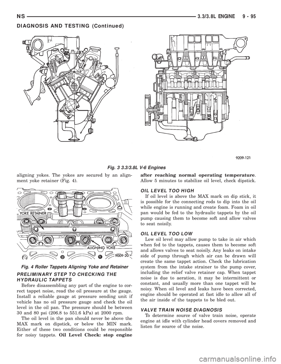
aligning yokes. The yokes are secured by an align-
ment yoke retainer (Fig. 4).
PRELIMINARY STEP TO CHECKING THE
HYDRAULIC TAPPETS
Before disassembling any part of the engine to cor-
rect tappet noise, read the oil pressure at the gauge.
Install a reliable gauge at pressure sending unit if
vehicle has no oil pressure gauge and check the oil
level in the oil pan. The pressure should be between
30 and 80 psi (206.8 to 551.6 kPa) at 2000 rpm.
The oil level in the pan should never be above the
MAX mark on dipstick, or below the MIN mark.
Either of these two conditions could be responsible
for noisy tappets.Oil Level Check: stop engineafter reaching normal operating temperature.
Allow 5 minutes to stabilize oil level, check dipstick.
OIL LEVEL TOO HIGH
If oil level is above the MAX mark on dip stick, it
is possible for the connecting rods to dip into the oil
while engine is running and create foam. Foam in oil
pan would be fed to the hydraulic tappets by the oil
pump causing them to become soft and allow valves
to seat noisily.
OIL LEVEL TOO LOW
Low oil level may allow pump to take in air which
when fed to the tappets, causes them to become soft
and allows valves to seat noisily. Any leaks on intake
side of pump through which air can be drawn will
create the same tappet action. Check the lubrication
system from the intake strainer to the pump cover,
including the relief valve retainer cap. When tappet
noise is due to aeration, it may be intermittent or
constant, and usually more than one tappet will be
noisy. When oil level and leaks have been corrected,
engine should be operated at fast idle to allow all of
the air inside of the tappets to be bled out.
VALVE TRAIN NOISE DIAGNOSIS
To determine source of valve train noise, operate
engine at idle with cylinder head covers removed and
listen for source of the noise.
Fig. 3 3.3/3.8L V-6 Engines
Fig. 4 Roller Tappets Aligning Yoke and Retainer
NS3.3/3.8L ENGINE 9 - 95
DIAGNOSIS AND TESTING (Continued)
Page 1155 of 1938
(20) Remove rear transmission mount and bracket.
(21) Remove power steering pump and bracket
assembly.
(22) Remove wiring harness and connectors from
front of engine.
(23) Remove bending braces and install tool num-
ber 6912 on engine.
(24) Remove transmission inspection cover and
mark flexplate to torque converter.
(25) Remove driveplate to torque converter bolts.
(26) Lower the vehicle.
(27) Remove ground straps to body.
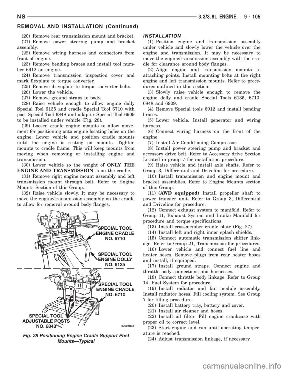
(28) Raise vehicle enough to allow engine dolly
Special Tool 6135 and cradle Special Tool 6710 with
post Special Tool 6848 and adaptor Special Tool 6909
to be installed under vehicle (Fig. 28).
(29) Loosen cradle engine mounts to allow move-
ment for positioning onto engine locating holes on the
engine. Lower vehicle and position cradle mounts
until the engine is resting on mounts. Tighten
mounts to cradle frame. This will keep mounts from
moving when removing or installing engine and
transmission.
(30) Lower vehicle so the weight ofONLY THE
ENGINE AND TRANSMISSIONis on the cradle.
(31) Remove right engine mount assembly and left
transmission mount through bolt. Refer to Engine
Mounts Section of this Group.
(32) Raise vehicle slowly. It may be necessary to
move the engine/transmission assembly on the cradle
to allow for removal around body flanges.INSTALLATION
(1) Position engine and transmission assembly
under vehicle and slowly lower the vehicle over the
engine and transmission. It may be necessary to
move the engine/transmission assembly with the cra-
dle for clearance around body flanges.
(2) Align engine and transmission mounts to
attaching points. Install mounting bolts at the right
engine and left transmission mounts. Refer to proce-
dures outlined in this section.
(3) Slowly raise vehicle enough to remove the
engine dolly and cradle Special Tools 6135, 6710,
6848 and 6909.
(4) Remove Special tools 6912 and install bending
braces.
(5) Lower vehicle. Install generator and wiring
harness.
(6) Connect wiring harness on the front of the
engine.
(7) Install Air Conditioning Compressor.
(8) Install power steering pump and bracket and
accessory drive belt. Refer to Accessory drive Section
Located in group 7 for installation procedure.
(9) Raise vehicle and install axle shafts. Refer to
Group 3, Differential and Driveline for procedure.
(10) Install transmission and engine mount and
bracket assemblies. Refer to Engine Mounts section
of this Group.
(11)(AWD equipped)Install propeller shaft to
power transfer unit. Refer to Group 3, Differential
and Driveline for procedure.
(12) Connect exhaust system to manifold. Refer to
Group 11, Exhaust System and Intake Manifold for
procedure and torque specifications.
(13) Install crossmember cradle plate (Fig. 27).
(14) Install left and right inner splash shields.
(15) Connect automatic transmission shifter link-
age. Refer to Group 21, Transmission for procedures.
(16) Lower vehicle and connect fuel line and
heater hoses. Remove plugs from rear heater hoses
and install, if equipped.
(17) Install ground straps. Connect engine and
throttle body connections and harnesses.
(18) Connect throttle body linkage. Refer to Group
14, Fuel System for procedure.
(19) Install radiator and fan module assembly.
Install radiator hoses. Fill cooling system. See Group
7 for filling procedure.
(20) Install battery tray, battery and cover.
(21) Install air cleaner and hoses.
(22) Install oil filter. Fill engine crankcase with
proper oil to correct level.
(23) Start engine and run until operating temper-
ature is reached.
(24) Adjust transmission linkage, if necessary.
Fig. 28 Positioning Engine Cradle Support Post
MountsÐTypical
NS3.3/3.8L ENGINE 9 - 105
REMOVAL AND INSTALLATION (Continued)