1996 CHRYSLER VOYAGER oil level
[x] Cancel search: oil levelPage 1162 of 1938
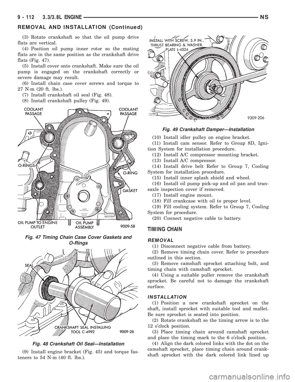
(3) Rotate crankshaft so that the oil pump drive
flats are vertical.
(4) Position oil pump inner rotor so the mating
flats are in the same position as the crankshaft drive
flats (Fig. 47).
(5) Install cover onto crankshaft. Make sure the oil
pump is engaged on the crankshaft correctly or
severe damage may result.
(6) Install chain case cover screws and torque to
27 N´m (20 ft. lbs.).
(7) Install crankshaft oil seal (Fig. 48).
(8) Install crankshaft pulley (Fig. 49).
(9) Install engine bracket (Fig. 45) and torque fas-
teners to 54 N´m (40 ft. lbs.).(10) Install idler pulley on engine bracket.
(11) Install cam sensor. Refer to Group 8D, Igni-
tion System for installation procedure.
(12) Install A/C compressor mounting bracket.
(13) Install A/C compressor.
(14) Install drive belt Refer to Group 7, Cooling
System for installation procedure.
(15) Install inner splash shield and wheel.
(16) Install oil pump pick-up and oil pan and tran-
saxle inspection cover if removed.
(17) Install engine mount.
(18) Fill crankcase with oil to proper level.
(19) Fill cooling system. Refer to Group 7, Cooling
System for procedure.
(20) Connect negative cable to battery.
TIMING CHAIN
REMOVAL
(1) Disconnect negative cable from battery.
(2) Remove timing chain cover. Refer to procedure
outlined in this section.
(3) Remove camshaft sprocket attaching bolt, and
timing chain with camshaft sprocket.
(4) Using a suitable puller remove the crankshaft
sprocket. Be careful not to damage the crankshaft
surface.
INSTALLATION
(1) Position a new crankshaft sprocket on the
shaft, install sprocket with suitable tool and mallet.
Be sure sprocket is seated into position.
(2) Rotate crankshaft so the timing arrow is to the
12 o'clock position.
(3) Place timing chain around camshaft sprocket
and place the timing mark to the 6 o'clock position.
(4) Align the dark colored links with the dot on the
camshaft sprocket, place timing chain around crank-
shaft sprocket with the dark colored link lined up
Fig. 47 Timing Chain Case Cover Gaskets and
O-Rings
Fig. 48 Crankshaft Oil SealÐInstallation
Fig. 49 Crankshaft DamperÐInstallation
9 - 112 3.3/3.8L ENGINENS
REMOVAL AND INSTALLATION (Continued)
Page 1164 of 1938
0.310 mm (0.012 in. Max.). If not within limits install
a new thrust plate.
(10) Each tappet reused must be installed in the
same position from which it was removed.When
camshaft is replaced, all of the tappets must be
replaced.
CAMSHAFT BEARINGS
REMOVAL
(1) With engine removed from vehicle and com-
pletely disassembled, drive out rear cam bearing core
hole plug.
(2) Install proper size adapters and horseshoe
washers (part of Tool C-3132-A) at back of each bear-
ing shell to be removed and drive out bearing shells
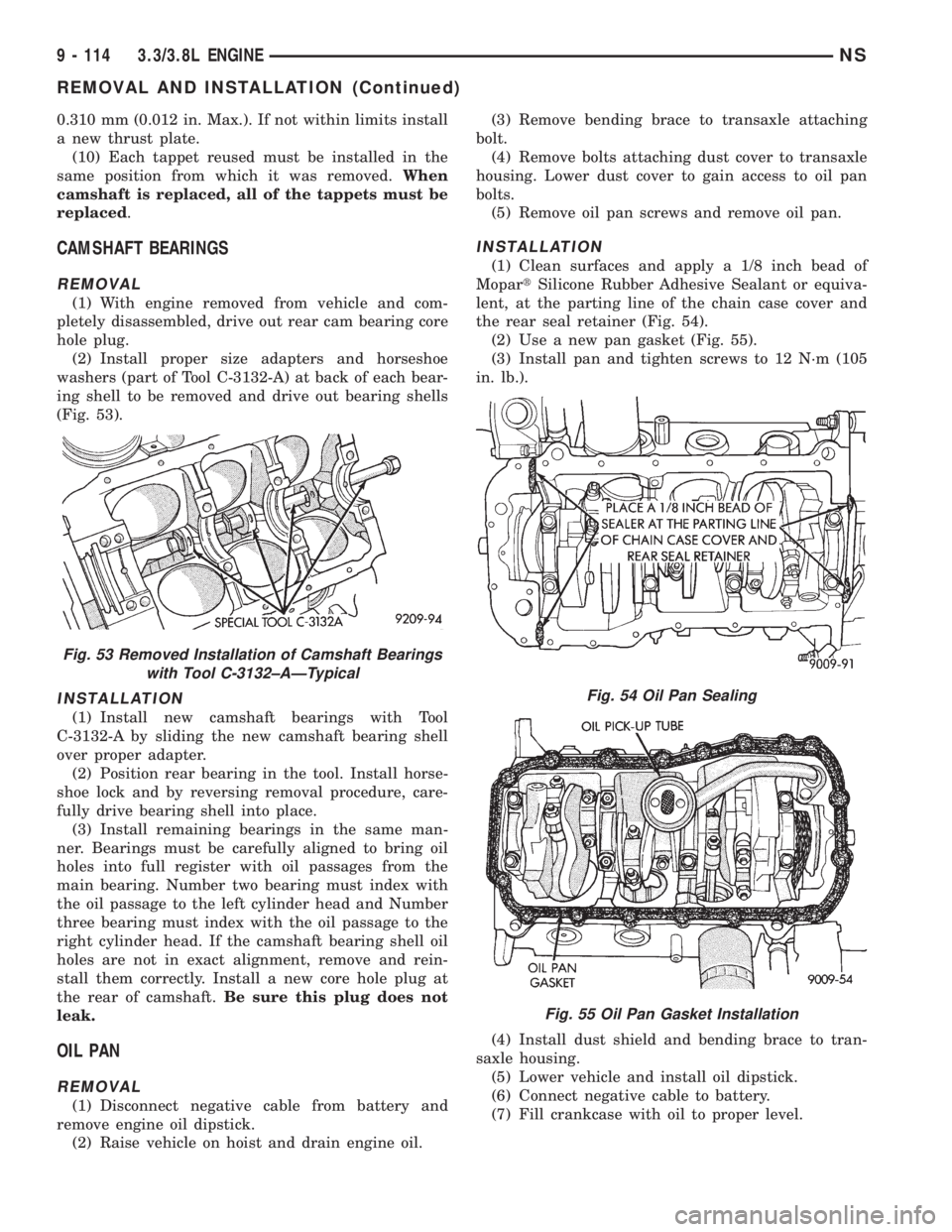
(Fig. 53).
INSTALLATION
(1) Install new camshaft bearings with Tool
C-3132-A by sliding the new camshaft bearing shell
over proper adapter.
(2) Position rear bearing in the tool. Install horse-
shoe lock and by reversing removal procedure, care-
fully drive bearing shell into place.
(3) Install remaining bearings in the same man-
ner. Bearings must be carefully aligned to bring oil
holes into full register with oil passages from the
main bearing. Number two bearing must index with
the oil passage to the left cylinder head and Number
three bearing must index with the oil passage to the
right cylinder head. If the camshaft bearing shell oil
holes are not in exact alignment, remove and rein-
stall them correctly. Install a new core hole plug at
the rear of camshaft.Be sure this plug does not
leak.
OIL PAN
REMOVAL
(1) Disconnect negative cable from battery and
remove engine oil dipstick.
(2) Raise vehicle on hoist and drain engine oil.(3) Remove bending brace to transaxle attaching
bolt.
(4) Remove bolts attaching dust cover to transaxle
housing. Lower dust cover to gain access to oil pan
bolts.
(5) Remove oil pan screws and remove oil pan.
INSTALLATION
(1) Clean surfaces and apply a 1/8 inch bead of
MopartSilicone Rubber Adhesive Sealant or equiva-
lent, at the parting line of the chain case cover and
the rear seal retainer (Fig. 54).
(2) Use a new pan gasket (Fig. 55).
(3) Install pan and tighten screws to 12 N´m (105
in. lb.).
(4) Install dust shield and bending brace to tran-
saxle housing.
(5) Lower vehicle and install oil dipstick.
(6) Connect negative cable to battery.
(7) Fill crankcase with oil to proper level.
Fig. 53 Removed Installation of Camshaft Bearings
with Tool C-3132±AÐTypical
Fig. 54 Oil Pan Sealing
Fig. 55 Oil Pan Gasket Installation
9 - 114 3.3/3.8L ENGINENS
REMOVAL AND INSTALLATION (Continued)
Page 1166 of 1938
(6) Tap the piston down in cylinder bore, using a
hammer handle. At the same time, guide connecting
rod into position on connecting rod journal.
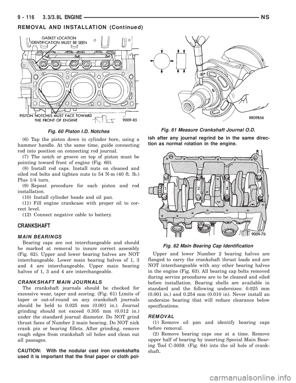
(7) The notch or groove on top of piston must be
pointing toward front of engine (Fig. 60).
(8) Install rod caps. Install nuts on cleaned and
oiled rod bolts and tighten nuts to 54 N´m (40 ft. lb.)
Plus 1/4 turn.
(9) Repeat procedure for each piston and rod
installation.
(10) Install cylinder heads and oil pan.
(11) Fill engine crankcase with proper oil to cor-
rect level.
(12) Connect negative cable to battery.
CRANKSHAFT
MAIN BEARINGS
Bearing caps are not interchangeable and should
be marked at removal to insure correct assembly
(Fig. 62). Upper and lower bearing halves are NOT
interchangeable. Lower main bearing halves of 1, 3
and 4 are interchangeable. Upper main bearing
halves of 1, 3 and 4 are interchangeable.
CRANKSHAFT MAIN JOURNALS
The crankshaft journals should be checked for
excessive wear, taper and scoring. (Fig. 61) Limits of
taper or out-of-round on any crankshaft journals
should be held to 0.025 mm (0.001 in.). Journal
grinding should not exceed 0.305 mm (0.012 in.)
under the standard journal diameter. Do NOT grind
thrust faces of Number 2 main bearing. Do NOT nick
crank pin or bearing fillets. After grinding, remove
rough edges from crankshaft oil holes and clean out
all passages.
CAUTION: With the nodular cast iron crankshafts
used it is important that the final paper or cloth pol-ish after any journal regrind be in the same direc-
tion as normal rotation in the engine.
Upper and lower Number 2 bearing halves are
flanged to carry the crankshaft thrust loads and are
NOT interchangeable with any other bearing halves
in the engine (Fig. 63). All bearing cap bolts removed
during service procedures are to be cleaned and oiled
before installation. Bearing shells are available in
standard and the following undersizes: 0.025 mm
(0.001 in.) and 0.254 mm (0.010 in). Never install an
undersize bearing that will reduce clearance below
specifications.
REMOVAL
(1) Remove oil pan and identify bearing caps
before removal.
(2) Remove bearing caps one at a time. Remove
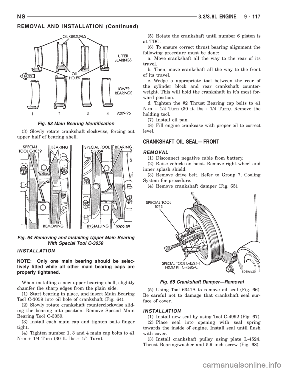
upper half of bearing by inserting Special Main Bear-
ing Tool C-3059. (Fig. 64) into the oil hole of crank-
shaft.
Fig. 60 Piston I.D. NotchesFig. 61 Measure Crankshaft Journal O.D.
Fig. 62 Main Bearing Cap Identification
9 - 116 3.3/3.8L ENGINENS
REMOVAL AND INSTALLATION (Continued)
Page 1167 of 1938
(3) Slowly rotate crankshaft clockwise, forcing out
upper half of bearing shell.
INSTALLATION
NOTE: Only one main bearing should be selec-
tively fitted while all other main bearing caps are
properly tightened.
When installing a new upper bearing shell, slightly
chamfer the sharp edges from the plain side.
(1) Start bearing in place, and insert Main Bearing
Tool C-3059 into oil hole of crankshaft (Fig. 64).
(2) Slowly rotate crankshaft counterclockwise slid-
ing the bearing into position. Remove Special Main
Bearing Tool C-3059.
(3) Install each main cap and tighten bolts finger
tight.
(4) Tighten number 1, 3 and 4 main cap bolts to 41
N´m + 1/4 Turn (30 ft. lbs.+ 1/4 Turn).(5) Rotate the crankshaft until number 6 piston is
at TDC.
(6) To ensure correct thrust bearing alignment the
following procedure must be done:
a. Move crankshaft all the way to the rear of its
travel.
b. Then, move crankshaft all the way to the front
of its travel.
c. Wedge a appropriate tool between the rear of
the cylinder block and rear crankshaft counter-
weight. This will hold the crankshaft in it's most for-
ward position.
d. Tighten the #2 Thrust Bearing cap bolts to 41
N´m + 1/4 Turn (30 ft. lbs.+ 1/4 Turn). Remove the
holding tool.
(7) Install oil pan.
(8) Fill engine crankcase with proper oil to correct
level.
CRANKSHAFT OIL SEALÐFRONT
REMOVAL
(1) Disconnect negative cable from battery.
(2) Raise vehicle on hoist. Remove right wheel and
inner splash shield.
(3) Remove drive belt. Refer to Group 7, Cooling
System for procedure.
(4) Remove crankshaft damper (Fig. 65).
(5) Using Tool 6341A to remove oil seal (Fig. 66).
Be careful not to damage that crankshaft seal sur-
face of cover.
INSTALLATION
(1) Install new seal by using Tool C-4992 (Fig. 67).
(2) Place seal into opening with seal spring
towards the inside of engine. Install seal until flush
with cover.
(3) Install crankshaft pulley using plate L-4524.
Thrust Bearing/washer and 5.9 inch screw (Fig. 68).
Fig. 63 Main Bearing Identification
Fig. 64 Removing and Installing Upper Main Bearing
With Special Tool C-3059
Fig. 65 Crankshaft DamperÐRemoval
NS3.3/3.8L ENGINE 9 - 117
REMOVAL AND INSTALLATION (Continued)
Page 1172 of 1938
(2) If new core plugs are installed, see Engine Core
Oil and Cam Plugs.
(3) Examine block for cracks or fractures.
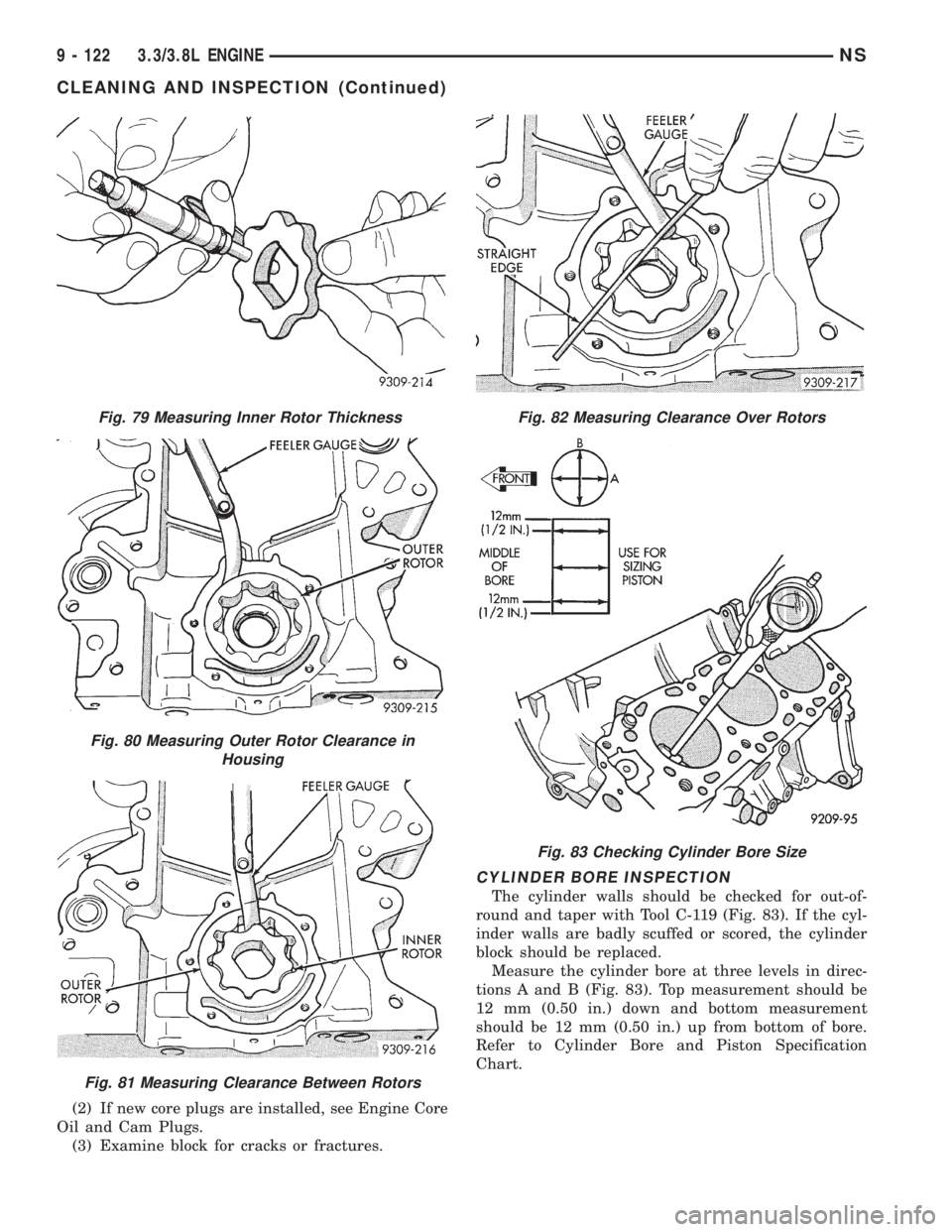
CYLINDER BORE INSPECTION
The cylinder walls should be checked for out-of-
round and taper with Tool C-119 (Fig. 83). If the cyl-
inder walls are badly scuffed or scored, the cylinder
block should be replaced.
Measure the cylinder bore at three levels in direc-
tions A and B (Fig. 83). Top measurement should be
12 mm (0.50 in.) down and bottom measurement
should be 12 mm (0.50 in.) up from bottom of bore.
Refer to Cylinder Bore and Piston Specification
Chart.
Fig. 79 Measuring Inner Rotor Thickness
Fig. 80 Measuring Outer Rotor Clearance in
Housing
Fig. 81 Measuring Clearance Between Rotors
Fig. 82 Measuring Clearance Over Rotors
Fig. 83 Checking Cylinder Bore Size
9 - 122 3.3/3.8L ENGINENS
CLEANING AND INSPECTION (Continued)
Page 1176 of 1938
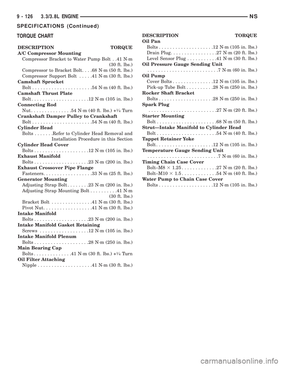
TORQUE CHART
DESCRIPTION TORQUE
A/C Compressor Mounting
Compressor Bracket to Water Pump Bolt . .41 N´m
(30 ft. lbs.)
Compressor to Bracket Bolt. . . .68 N´m (50 ft. lbs.)
Compressor Support Bolt.....41N´m(30ft.lbs.)
Camshaft Sprocket
Bolt......................54N´m(40ft.lbs.)
Camshaft Thrust Plate
Bolt.....................12N´m(105 in. lbs.)
Connecting Rod
Nut...............54N´m(40ft.lbs.) +
1¤4Turn
Crankshaft Damper Pulley to Crankshaft
Bolt......................54N´m(40ft.lbs.)
Cylinder Head
Bolts.......Refer to Cylinder Head Removal and
Installation Procedure in this Section
Cylinder Head Cover
Bolts....................12N´m(105 in. lbs.)
Exhaust Manifold
Bolts....................23N´m(200 in. lbs.)
Exhaust Crossover Pipe Flange
Fasteners..................33N´m(25ft.lbs.)
Generator Mounting
Adjusting Strap Bolt........23N´m(200 in. lbs.)
Adjusting Strap Mounting Bolt..........41N´m
(30 ft. lbs.)
Bracket Bolt...............41N´m(30ft.lbs.)
Pivot Nut..................41N´m(30ft.lbs.)
Intake Manifold
Bolts....................23N´m(200 in. lbs.)
Intake Manifold Gasket Retaining
Screws..................12N´m(105 in. lbs.)
Intake Manifold Plenum
Bolts....................28N´m(250 in. lbs.)
Main Bearing Cap
Bolts..............41N´m(30ft.lbs.) +
1¤4Turn
Oil Filter Attaching
Nipple....................41N´m(30ft.lbs.)DESCRIPTION TORQUE
Oil Pan
Bolts....................12N´m(105 in. lbs.)
Drain Plug.................27N´m(20ft.lbs.)
Level Sensor Plug...........41N´m(30ft.lbs.)
Oil Pressure Gauge Sending Unit
..........................7N´m(60in.lbs.)
Oil Pump
Cover Bolts...............12N´m(105 in. lbs.)
Pick-up Tube Bolt..........28N´m(250 in. lbs.)
Rocker Shaft Bracket
Bolts....................28N´m(250 in. lbs.)
Spark Plug
.........................27N´m(20ft.lbs.)
Starter Mounting
Bolt......................68N´m(50ft.lbs.)
StrutÐIntake Manifold to Cylinder Head
Bolt......................54N´m(40ft.lbs.)
Tappet Retainer Yoke
Bolt.....................12N´m(105 in. lbs.)
Temperature Gauge Sending Unit
..........................7N´m(60in.lbs.)
Timing Chain Case Cover
Bolt±M831.25.............27N´m(20ft.lbs.)
Bolt±M1031.5.............54N´m(40ft.lbs.)
Water Pump to Chain Case Cover
Bolts....................12N´m(105 in. lbs.)
9 - 126 3.3/3.8L ENGINENS
SPECIFICATIONS (Continued)
Page 1182 of 1938
(4) If oil pressure is 0 at idle. Shut off engine,
check for pressure relief valve stuck open, a clogged
oil pick-up screen or a damaged oil pick-up tube
O-ring.
SERVICE PROCEDURES
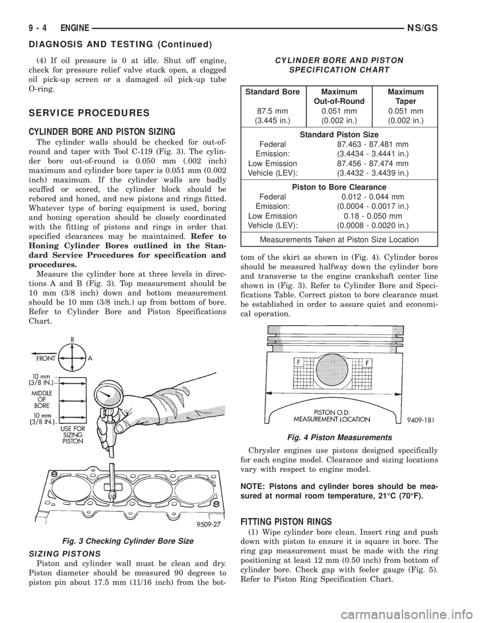
CYLINDER BORE AND PISTON SIZING
The cylinder walls should be checked for out-of-
round and taper with Tool C-119 (Fig. 3). The cylin-
der bore out-of-round is 0.050 mm (.002 inch)
maximum and cylinder bore taper is 0.051 mm (0.002
inch) maximum. If the cylinder walls are badly
scuffed or scored, the cylinder block should be
rebored and honed, and new pistons and rings fitted.
Whatever type of boring equipment is used, boring
and honing operation should be closely coordinated
with the fitting of pistons and rings in order that
specified clearances may be maintained.Refer to
Honing Cylinder Bores outlined in the Stan-
dard Service Procedures for specification and
procedures.
Measure the cylinder bore at three levels in direc-
tions A and B (Fig. 3). Top measurement should be
10 mm (3/8 inch) down and bottom measurement
should be 10 mm (3/8 inch.) up from bottom of bore.
Refer to Cylinder Bore and Piston Specifications
Chart.
SIZING PISTONS
Piston and cylinder wall must be clean and dry.
Piston diameter should be measured 90 degrees to
piston pin about 17.5 mm (11/16 inch) from the bot-tom of the skirt as shown in (Fig. 4). Cylinder bores
should be measured halfway down the cylinder bore
and transverse to the engine crankshaft center line
shown in (Fig. 3). Refer to Cylinder Bore and Speci-
fications Table. Correct piston to bore clearance must
be established in order to assure quiet and economi-
cal operation.
Chrysler engines use pistons designed specifically
for each engine model. Clearance and sizing locations
vary with respect to engine model.
NOTE: Pistons and cylinder bores should be mea-
sured at normal room temperature, 21ÉC (70ÉF).
FITTING PISTON RINGS
(1) Wipe cylinder bore clean. Insert ring and push
down with piston to ensure it is square in bore. The
ring gap measurement must be made with the ring
positioning at least 12 mm (0.50 inch) from bottom of
cylinder bore. Check gap with feeler gauge (Fig. 5).
Refer to Piston Ring Specification Chart.
Fig. 3 Checking Cylinder Bore Size
CYLINDER BORE AND PISTON
SPECIFICATION CHART
Standard Bore Maximum
Out-of-RoundMaximum
Taper
87.5 mm
(3.445 in.)0.051 mm
(0.002 in.)0.051 mm
(0.002 in.)
Standard Piston Size
Federal
Emission:87.463 - 87.481 mm
(3.4434 - 3.4441 in.)
Low Emission
Vehicle (LEV):87.456 - 87.474 mm
(3.4432 - 3.4439 in.)
Piston to Bore Clearance
Federal
Emission:0.012 - 0.044 mm
(0.0004 - 0.0017 in.)
Low Emission
Vehicle (LEV):0.18 - 0.050 mm
(0.0008 - 0.0020 in.)
Measurements Taken at Piston Size Location
Fig. 4 Piston Measurements
9 - 4 ENGINENS/GS
DIAGNOSIS AND TESTING (Continued)
Page 1218 of 1938
2.5L VM DIESEL
INDEX
page page
GENERAL INFORMATION
ENGINE IDENTIFICATION................ 41
GENERAL SPECIFICATION............... 40
DESCRIPTION AND OPERATION
LUBRICATION SYSTEM.................. 41
DIAGNOSIS AND TESTING
ENGINE DIAGNOSISÐMECHANICAL....... 44
ENGINE DIAGNOSISÐPERFORMANCE..... 43
HYDRAULIC TAPPETS................... 47
SERVICE PROCEDURES
CHANGING ENGINE OIL AND FILTER....... 47
CHECKING OIL LEVEL................... 47
CRANKSHAFT END PLAY................ 50
FITTING PISTON RING.................. 50
TIMING PROCEDURE................... 49
VALVE AND SEAT REFACING............. 49
REMOVAL AND INSTALLATION
CAMSHAFT........................... 62
CAMSHAFT BEARINGS.................. 63
CRANKSHAFT MAIN BEARINGS........... 63
CRANKSHAFTÐREMOVAL............... 72
CYLINDER HEAD....................... 55
CYLINDER HEAD COVER................ 54
CYLINDER LINER...................... 72
ENGINE ASSEMBLY..................... 53
ENGINE MOUNTÐFRONT................ 51
ENGINE MOUNTÐREAR................. 52
ENGINE MOUNTÐRIGHT................ 51
HYDRAULIC TAPPETS................... 60
INJECTION PUMP...................... 61
MOUNTÐLEFT SIDE.................... 51
OIL FILTER ADAPTER AND OIL COOLER.... 68
OILPAN .............................. 66OIL PUMP............................ 67
OIL PUMP PRESSURE RELIEF VALVE...... 67
PISTONS AND CONNECTING ROD......... 68
REAR CRANKSHAFT OIL SEAL............ 72
ROCKER ARMS AND PUSH RODS......... 54
TIMING GEAR COVER................... 61
TIMING GEAR COVER OIL SEAL........... 61
VACUUM PUMP........................ 68
VALVE SPRINGSÐCYLINDER HEAD NOT
REMOVED.......................... 55
VALVES AND VALVE SPRINGSÐHEAD OFF . . 60
VIBRATION DAMPER.................... 61
DISASSEMBLY AND ASSEMBLY
HYDRAULIC TAPPETS................... 73
CLEANING AND INSPECTION
CRANKSHAFT......................... 77
CRANKSHAFT MAIN BEARING............ 77
CYLINDER HEAD....................... 75
CYLINDER HEAD COVERS............... 74
CYLINDER LINER...................... 78
HYDRAULIC TAPPETS................... 76
OILPAN .............................. 78
OIL PUMP............................ 76
PISTON AND CONNECTING ROD.......... 76
ROCKER ARMS AND PUSH RODS......... 74
TIMING GEAR COVER................... 75
VALVES AND VALVE SPRINGS............ 76
SPECIFICATIONS
2.5L VM DIESEL........................ 78
TORQUE............................. 80
SPECIAL TOOLS
2.5L VM DIESEL........................ 81
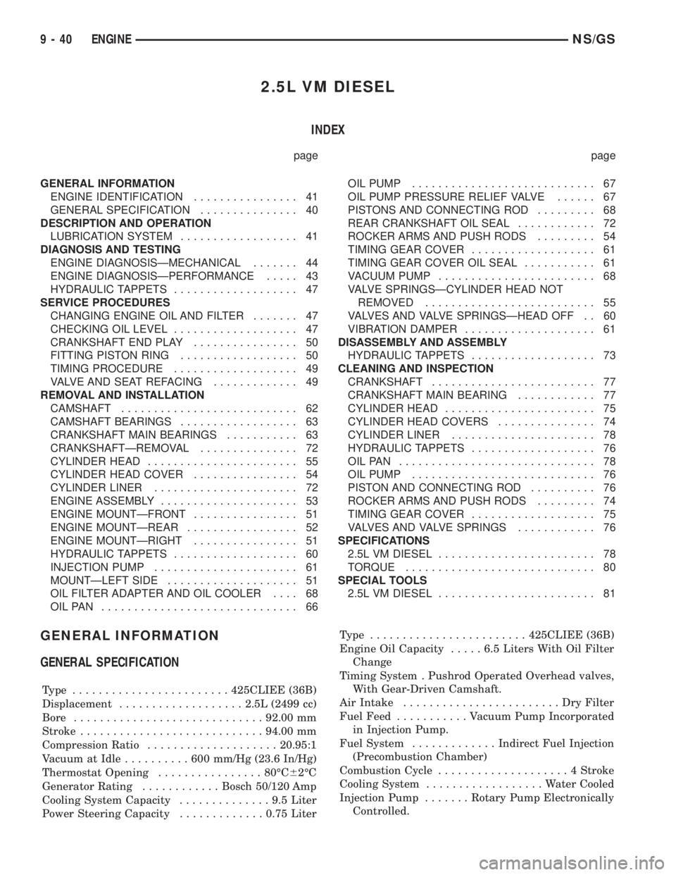
GENERAL INFORMATION
GENERAL SPECIFICATION
Type ........................425CLIEE (36B)
Displacement...................2.5L (2499 cc)
Bore.............................92.00 mm
Stroke............................94.00 mm
Compression Ratio....................20.95:1
Vacuum at Idle..........600mm/Hg (23.6 In/Hg)
Thermostat Opening................80ÉC62ÉC
Generator Rating............Bosch 50/120 Amp
Cooling System Capacity..............9.5Liter
Power Steering Capacity.............0.75 LiterType ........................425CLIEE (36B)
Engine Oil Capacity.....6.5Liters With Oil Filter
Change
Timing System . Pushrod Operated Overhead valves,
With Gear-Driven Camshaft.
Air Intake........................DryFilter
Fuel Feed...........Vacuum Pump Incorporated
in Injection Pump.
Fuel System.............Indirect Fuel Injection
(Precombustion Chamber)
Combustion Cycle....................4Stroke
Cooling System..................Water Cooled
Injection Pump.......Rotary Pump Electronically
Controlled.
9 - 40 ENGINENS/GS