1996 CHRYSLER VOYAGER checking oil
[x] Cancel search: checking oilPage 1218 of 1938
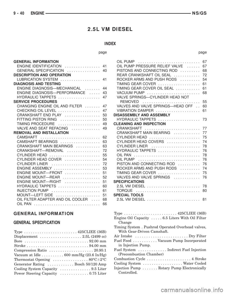
2.5L VM DIESEL
INDEX
page page
GENERAL INFORMATION
ENGINE IDENTIFICATION................ 41
GENERAL SPECIFICATION............... 40
DESCRIPTION AND OPERATION
LUBRICATION SYSTEM.................. 41
DIAGNOSIS AND TESTING
ENGINE DIAGNOSISÐMECHANICAL....... 44
ENGINE DIAGNOSISÐPERFORMANCE..... 43
HYDRAULIC TAPPETS................... 47
SERVICE PROCEDURES
CHANGING ENGINE OIL AND FILTER....... 47
CHECKING OIL LEVEL................... 47
CRANKSHAFT END PLAY................ 50
FITTING PISTON RING.................. 50
TIMING PROCEDURE................... 49
VALVE AND SEAT REFACING............. 49
REMOVAL AND INSTALLATION
CAMSHAFT........................... 62
CAMSHAFT BEARINGS.................. 63
CRANKSHAFT MAIN BEARINGS........... 63
CRANKSHAFTÐREMOVAL............... 72
CYLINDER HEAD....................... 55
CYLINDER HEAD COVER................ 54
CYLINDER LINER...................... 72
ENGINE ASSEMBLY..................... 53
ENGINE MOUNTÐFRONT................ 51
ENGINE MOUNTÐREAR................. 52
ENGINE MOUNTÐRIGHT................ 51
HYDRAULIC TAPPETS................... 60
INJECTION PUMP...................... 61
MOUNTÐLEFT SIDE.................... 51
OIL FILTER ADAPTER AND OIL COOLER.... 68
OILPAN .............................. 66OIL PUMP............................ 67
OIL PUMP PRESSURE RELIEF VALVE...... 67
PISTONS AND CONNECTING ROD......... 68
REAR CRANKSHAFT OIL SEAL............ 72
ROCKER ARMS AND PUSH RODS......... 54
TIMING GEAR COVER................... 61
TIMING GEAR COVER OIL SEAL........... 61
VACUUM PUMP........................ 68
VALVE SPRINGSÐCYLINDER HEAD NOT
REMOVED.......................... 55
VALVES AND VALVE SPRINGSÐHEAD OFF . . 60
VIBRATION DAMPER.................... 61
DISASSEMBLY AND ASSEMBLY
HYDRAULIC TAPPETS................... 73
CLEANING AND INSPECTION
CRANKSHAFT......................... 77
CRANKSHAFT MAIN BEARING............ 77
CYLINDER HEAD....................... 75
CYLINDER HEAD COVERS............... 74
CYLINDER LINER...................... 78
HYDRAULIC TAPPETS................... 76
OILPAN .............................. 78
OIL PUMP............................ 76
PISTON AND CONNECTING ROD.......... 76
ROCKER ARMS AND PUSH RODS......... 74
TIMING GEAR COVER................... 75
VALVES AND VALVE SPRINGS............ 76
SPECIFICATIONS
2.5L VM DIESEL........................ 78
TORQUE............................. 80
SPECIAL TOOLS
2.5L VM DIESEL........................ 81
GENERAL INFORMATION
GENERAL SPECIFICATION
Type ........................425CLIEE (36B)
Displacement...................2.5L (2499 cc)
Bore.............................92.00 mm
Stroke............................94.00 mm
Compression Ratio....................20.95:1
Vacuum at Idle..........600mm/Hg (23.6 In/Hg)
Thermostat Opening................80ÉC62ÉC
Generator Rating............Bosch 50/120 Amp
Cooling System Capacity..............9.5Liter
Power Steering Capacity.............0.75 LiterType ........................425CLIEE (36B)
Engine Oil Capacity.....6.5Liters With Oil Filter
Change
Timing System . Pushrod Operated Overhead valves,
With Gear-Driven Camshaft.
Air Intake........................DryFilter
Fuel Feed...........Vacuum Pump Incorporated
in Injection Pump.
Fuel System.............Indirect Fuel Injection
(Precombustion Chamber)
Combustion Cycle....................4Stroke
Cooling System..................Water Cooled
Injection Pump.......Rotary Pump Electronically
Controlled.
9 - 40 ENGINENS/GS
Page 1225 of 1938
HYDRAULIC TAPPETS
Before disassembling any part of the engine to cor-
rect tappet noise, check the oil pressure. If vehicle
has no oil pressure gauge, install a reliable gauge at
the pressure sending unit. The pressure should be
between 3.5 bars to 5.0 bars at 4000 RPM.
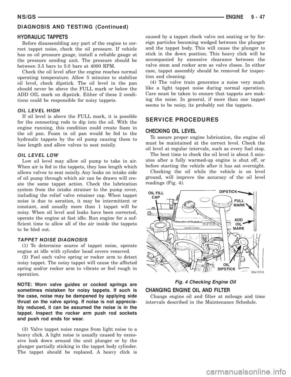
Check the oil level after the engine reaches normal
operating temperature. Allow 5 minutes to stabilize
oil level, check dipstick. The oil level in the pan
should never be above the FULL mark or below the
ADD OIL mark on dipstick. Either of these 2 condi-
tions could be responsible for noisy tappets.
OIL LEVEL HIGH
If oil level is above the FULL mark, it is possible
for the connecting rods to dip into the oil. With the
engine running, this condition could create foam in
the oil pan. Foam in oil pan would be fed to the
hydraulic tappets by the oil pump causing them to
lose length and allow valves to seat noisily.
OIL LEVEL LOW
Low oil level may allow oil pump to take in air.
When air is fed to the tappets, they lose length which
allows valves to seat noisily. Any leaks on intake side
of oil pump through which air can be drawn will cre-
ate the same tappet action. Check the lubrication
system from the intake strainer to the pump cover,
including the relief valve retainer cap. When tappet
noise is due to aeration, it may be intermittent or
constant, and usually more than 1 tappet will be
noisy. When oil level and leaks have been corrected,
operate the engine at fast idle. Run engine for a suf-
ficient time to allow all of the air inside the tappets
to be bled out.
TAPPET NOISE DIAGNOSIS
(1) To determine source of tappet noise, operate
engine at idle with cylinder head covers removed.
(2) Feel each valve spring or rocker arm to detect
noisy tappet. The noisy tappet will cause the affected
spring and/or rocker arm to vibrate or feel rough in
operation.
NOTE: Worn valve guides or cocked springs are
sometimes mistaken for noisy tappets. If such is
the case, noise may be dampened by applying side
thrust on the valve spring. If noise is not apprecia-
bly reduced, it can be assumed the noise is in the
tappet. Inspect the rocker arm push rod sockets
and push rod ends for wear.
(3) Valve tappet noise ranges from light noise to a
heavy click. A light noise is usually caused by exces-
sive leak down around the unit plunger or by the
plunger partially sticking in the tappet body cylinder.
The tappet should be replaced. A heavy click iscaused by a tappet check valve not seating or by for-
eign particles becoming wedged between the plunger
and the tappet body. This will cause the plunger to
stick in the down position. This heavy click will be
accompanied by excessive clearance between the
valve stem and rocker arm as valve closes. In either
case, tappet assembly should be removed for inspec-
tion and cleaning.
(4) The valve train generates a noise very much
like a light tappet noise during normal operation.
Care must be taken to ensure that tappets are mak-
ing the noise. In general, if more than one tappet
seems to be noisy, its probably not the tappets.
SERVICE PROCEDURES
CHECKING OIL LEVEL
To assure proper engine lubrication, the engine oil
must be maintained at the correct level. Check the
oil level at regular intervals, such as every fuel stop.
The best time to check the oil level is about 5 min-
utes after a fully warmed-up engine is shut off, or
before starting the vehicle after it has sat overnight.
Checking the oil while the vehicle is on level
ground, will improve the accuracy of the oil level
readings (Fig. 4).
CHANGING ENGINE OIL AND FILTER
Change engine oil and filter at mileage and time
intervals described in the Maintenance Schedule.
Fig. 4 Checking Engine Oil
NS/GSENGINE 9 - 47
DIAGNOSIS AND TESTING (Continued)
Page 1228 of 1938
VALVE STAND DOWN
Valve stand down is to maintain the adequate com-
pression ratio.
(1) Invert cylinder head.
(2) Fit each valve to its respective valve guide.
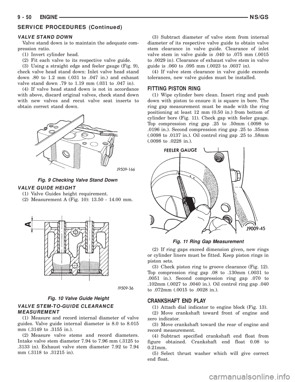
(3) Using a straight edge and feeler gauge (Fig. 9),
check valve head stand down: Inlet valve head stand
down .80 to 1.2 mm (.031 to .047 in.) and exhaust
valve stand down .79 to 1.19 mm (.031 to .047 in).
(4) If valve head stand down is not in accordance
with above, discard original valves, check stand down
with new valves and recut valve seat inserts to
obtain correct stand down.
VALVE GUIDE HEIGHT
(1) Valve Guides height requirement.
(2) Measurement A (Fig. 10): 13.50 - 14.00 mm.
VALVE STEM-TO-GUIDE CLEARANCE
MEASUREMENT
(1) Measure and record internal diameter of valve
guides. Valve guide internal diameter is 8.0 to 8.015
mm (.3149 to .3155 in.).
(2) Measure valve stems and record diameters.
Intake valve stem diameter 7.94 to 7.96 mm (.3125 to
.3133 in). Exhaust valve stem diameter 7.92 to 7.94
mm (.3118 to .31215 in).(3) Subtract diameter of valve stem from internal
diameter of its respective valve guide to obtain valve
stem clearance in valve guide. Clearance of inlet
valve stem in valve guide is .040 to .075 mm (.0015
to .0029 in). Clearance of exhaust valve stem in valve
guide is .060 to .095 mm (.0023 to .0037 in).
(4) If valve stem clearance in valve guide exceeds
tolerances, new valve guides must be installed.
FITTING PISTON RING
(1) Wipe cylinder bore clean. Insert ring and push
down with piston to ensure it is square in bore. The
ring gap measurement must be made with the ring
positioning at least 12 mm (0.50 in.) from bottom of
cylinder bore (Fig. 11). Check gap with feeler gauge.
Top compression ring gap .25 to .50mm (.0098 to
.0196 in.). Second compression ring gap .25 to .35mm
(.0098 to .0137 in.). Oil control ring gap .25 to .58mm
(.0098 to .0228 in.).
(2) If ring gaps exceed dimension given, new rings
or cylinder liners must be fitted. Keep piston rings in
piston sets.
(3) Check piston ring to groove clearance (Fig. 12).
Top compression ring gap .08 to .130mm (.0031 to
.0051 in.). Second compression ring gap .070 to
.102mm (.0027 to .0040 in.). Oil control ring gap .040
to .072mm (.0015 to .0028 in.).
CRANKSHAFT END PLAY
(1) Attach dial indicator to engine block (Fig. 13).
(2) Move crankshaft toward front of engine and
zero indicator.
(3) Move crankshaft toward the rear of engine and
record measurement.
(4) Subtract specified crankshaft end float from
figure obtained. Crankshaft end float 0.08 to
0.21mm.
(5) Select thrust washer which will give correct
end float.
Fig. 9 Checking Valve Stand Down
Fig. 10 Valve Guide Height
Fig. 11 Ring Gap Measurement
9 - 50 ENGINENS/GS
SERVICE PROCEDURES (Continued)
Page 1242 of 1938
(13) Remove pistons and connecting rods from
block.
(14) Remove vibration damper. Refer to procedure
in this section.
(15) Remove front cover. Refer to procedure in this
section.
(16) Remove oil pump drive gear.
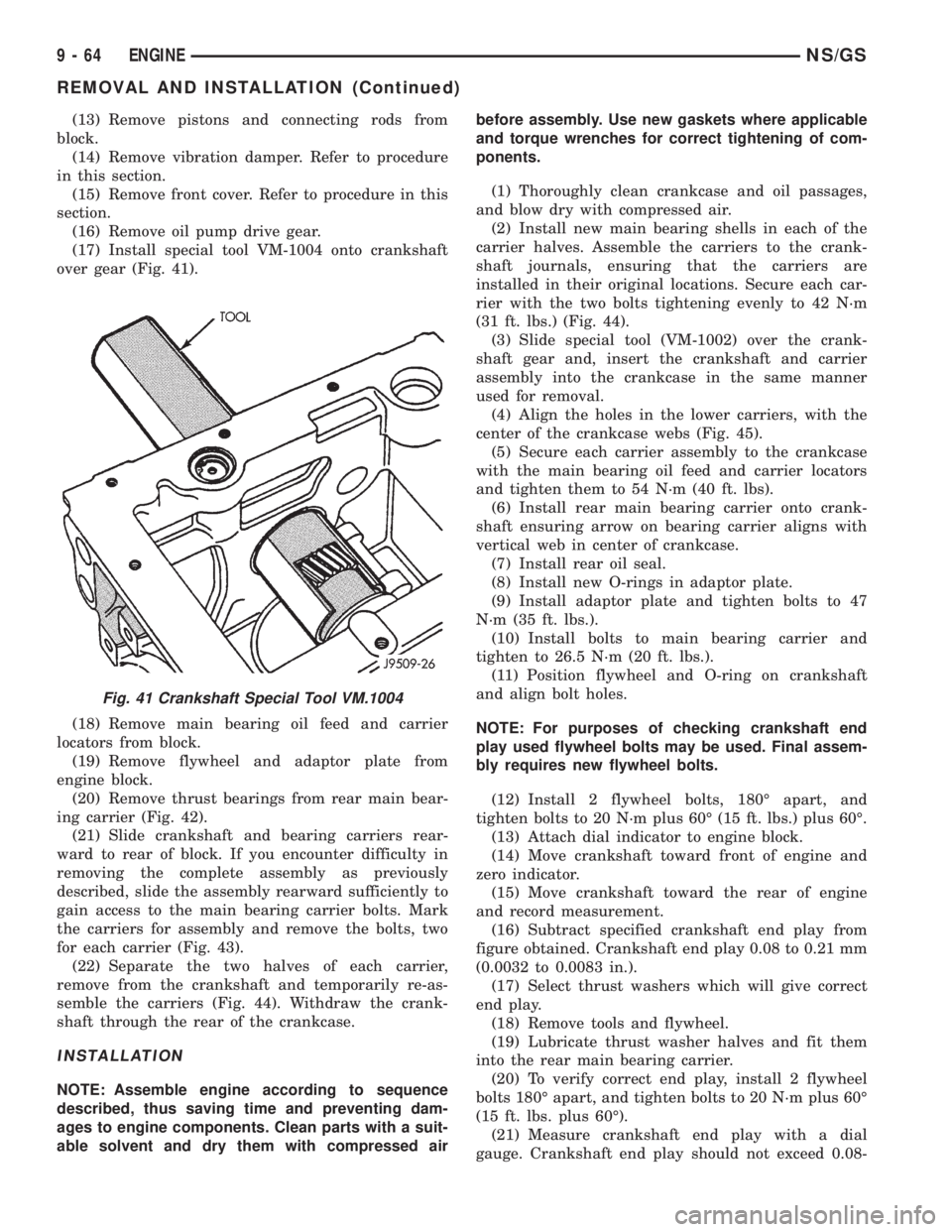
(17) Install special tool VM-1004 onto crankshaft
over gear (Fig. 41).
(18) Remove main bearing oil feed and carrier
locators from block.
(19) Remove flywheel and adaptor plate from
engine block.
(20) Remove thrust bearings from rear main bear-
ing carrier (Fig. 42).
(21) Slide crankshaft and bearing carriers rear-
ward to rear of block. If you encounter difficulty in
removing the complete assembly as previously
described, slide the assembly rearward sufficiently to
gain access to the main bearing carrier bolts. Mark
the carriers for assembly and remove the bolts, two
for each carrier (Fig. 43).
(22) Separate the two halves of each carrier,
remove from the crankshaft and temporarily re-as-
semble the carriers (Fig. 44). Withdraw the crank-
shaft through the rear of the crankcase.
INSTALLATION
NOTE: Assemble engine according to sequence
described, thus saving time and preventing dam-
ages to engine components. Clean parts with a suit-
able solvent and dry them with compressed airbefore assembly. Use new gaskets where applicable
and torque wrenches for correct tightening of com-
ponents.
(1) Thoroughly clean crankcase and oil passages,
and blow dry with compressed air.
(2) Install new main bearing shells in each of the
carrier halves. Assemble the carriers to the crank-
shaft journals, ensuring that the carriers are
installed in their original locations. Secure each car-
rier with the two bolts tightening evenly to 42 N´m
(31 ft. lbs.) (Fig. 44).
(3) Slide special tool (VM-1002) over the crank-
shaft gear and, insert the crankshaft and carrier
assembly into the crankcase in the same manner
used for removal.
(4) Align the holes in the lower carriers, with the
center of the crankcase webs (Fig. 45).
(5) Secure each carrier assembly to the crankcase
with the main bearing oil feed and carrier locators
and tighten them to 54 N´m (40 ft. lbs).
(6) Install rear main bearing carrier onto crank-
shaft ensuring arrow on bearing carrier aligns with
vertical web in center of crankcase.
(7) Install rear oil seal.
(8) Install new O-rings in adaptor plate.
(9) Install adaptor plate and tighten bolts to 47
N´m (35 ft. lbs.).
(10) Install bolts to main bearing carrier and
tighten to 26.5 N´m (20 ft. lbs.).
(11) Position flywheel and O-ring on crankshaft
and align bolt holes.
NOTE: For purposes of checking crankshaft end
play used flywheel bolts may be used. Final assem-
bly requires new flywheel bolts.
(12) Install 2 flywheel bolts, 180É apart, and
tighten bolts to 20 N´m plus 60É (15 ft. lbs.) plus 60É.
(13) Attach dial indicator to engine block.
(14) Move crankshaft toward front of engine and
zero indicator.
(15) Move crankshaft toward the rear of engine
and record measurement.
(16) Subtract specified crankshaft end play from
figure obtained. Crankshaft end play 0.08 to 0.21 mm
(0.0032 to 0.0083 in.).
(17) Select thrust washers which will give correct
end play.
(18) Remove tools and flywheel.
(19) Lubricate thrust washer halves and fit them
into the rear main bearing carrier.
(20) To verify correct end play, install 2 flywheel
bolts 180É apart, and tighten bolts to 20 N´m plus 60É
(15 ft. lbs. plus 60É).
(21) Measure crankshaft end play with a dial
gauge. Crankshaft end play should not exceed 0.08-
Fig. 41 Crankshaft Special Tool VM.1004
9 - 64 ENGINENS/GS
REMOVAL AND INSTALLATION (Continued)
Page 1439 of 1938
(18) Remove the 3 previously loosened bolts
attaching the front bracket to the power steering
pump and separate the power steering pump from
the front bracket prior to removing the pump from
the vehicle.
(19) The power steering pump is removed from the
vehicle by pulling it out through the exhaust tunnel
area in the floor pan of the vehicle.
INSTALL
(1) Install power steering pump back in vehicle
using the reverse order of its removal through the
exhaust tunnel are of the vehicle.
(2) Install the power steering pump on its cast
mounting bracket and loosely install nut to hold
pump in place (Fig. 9).
(3) Install the front bracket on the power steering
pump and loosely install the 3 mounting bolts (Fig.
10). Then install the nut and bolt attaching the front
bracket to the cast bracket (Fig. 10).
(4) Tighten the 3 power steering pump mounting
bolts (Fig. 10) to a torque of 54 N´m (40 ft. lbs.).
NOTE: Before installing power steering fluid pres-
sure hose on power steering pump, inspect the
O-ring on the pressure hose for damage and
replace if necessary.
(5) Install the power steering fluid pressure line
onto the output fitting of the power steering pump
(Fig. 8). Tighten the pressure line to pump fitting
tube nut to a torque of 31 N´m (275 in. lbs.).
(6) Install the power steering fluid, low pressure
return hose on the power steering pump low pressure
fitting (Fig. 8).Be sure hose clamps are properly
reinstalled.
(7) Install the power steering fluid supply hose
from the power steering fluid reservoir, on the power
steering pump fluid fitting (Fig. 7).Be sure hose is
clear of accessory drive belts all hose clamps
are properly reinstalled.
(8) Install the power steering pump drive belt on
pulley. See Cooling, Group 7 for detailed installation
procedure.
(9) Install the accessory drive splash shield (Fig.
6).
(10) Install the power steering fluid return hose on
the steel tube at the front suspension cradle (Fig. 5).
(11) Install a screw type hose clamp on the power
steering hose to steel tube connection.Be sure hose
clamps are properly reinstalled.Tighten the screw
clamp to a torque of 2 N´m (18 in. lbs.).
CAUTION: The protective heat shield sleeves must
cover the entire rubber hose and hose to tube con-
nection portion of both the power steering fluid
pressure and return hoses (Fig. 5). This is requiredto prevent the overheating of the power steering
hoses.
(12) When used, properly position the protective
heat sleeves on the power steering hoses (Fig. 5).
Then, tie strap the heat sleeves to the power steering
hoses to keep them in their proper position.
(13) Install the exhaust pipe on the exhaust man-
ifold. Install all exhaust system hangers/isolators on
the exhaust system brackets.
(14) Connect the oxygen sensor wiring harness to
the vehicle wiring harness. Install wiring harness
grommet in the floor pan of the vehicle.
(15) Lower vehicle.
(16) Adjust the power steering pump drive belt.
See Cooling, Group 7 for detailed adjustment proce-
dure.
(17) Tighten the top nut and bottom bolt on the
power steering pump front mounting bracket (Fig. 3)
to a torque of 54 N´m (40 ft. lbs.).
CAUTION: Do not use automatic transmission fluid
in power steering system. Only use MoparT, Power
Steering Fluid, or equivalent.
(18) Fill the remote power steering pump fluid res-
ervoir to correct fluid level.
(19) Install cap on power steering fluid reservoir.
(20) Connect the negative battery cable on the
negative battery post.
(21) Start engine and turn steering wheel several
times from stop to stop to bleed air from fluid in sys-
tem. Stop engine, check fluid level, and inspect sys-
tem for leaks. See Checking Fluid Level.
3.0 LITER POWER STEERING PUMP
REMOVE
WARNING: POWER STEERING OIL, ENGINE COM-
PONENTS AND THE EXHAUST SYSTEM MAY BE
EXTREMELY HOT IF ENGINE HAS BEEN RUNNING.
DO NOT START ENGINE WITH ANY LOOSE OR DIS-
CONNECTED HOSES. DO NOT ALLOW HOSES TO
TOUCH HOT EXHAUST MANIFOLD OR CATALYST.
(1) Remove the (-) negative battery cable from the
battery and isolate cable.
(2) Remove cap from power steering fluid reser-
voir.
(3) Using a siphon pump, remove as much power
steering fluid as possible from the power steering
fluid reservoir.
NSSTEERING 19 - 13
REMOVAL AND INSTALLATION (Continued)
Page 1442 of 1938
(15) Fill the remote power steering pump fluid res-
ervoir to correct fluid level.
(16) Install cap on power steering fluid reservoir.
(17) Connect the negative battery cable on the
negative battery post.
(18) Start engine and turn steering wheel several
times from stop to stop to bleed air from fluid in sys-
tem. Stop engine, check fluid level, and inspect sys-
tem for leaks. See Checking Fluid Level.
3.3/3.8 LITER POWER STEERING PUMP
REMOVE
WARNING: POWER STEERING OIL, ENGINE COM-
PONENTS AND THE EXHAUST SYSTEM MAY BE
EXTREMELY HOT IF ENGINE HAS BEEN RUNNING.
DO NOT START ENGINE WITH ANY LOOSE OR DIS-
CONNECTED HOSES. DO NOT ALLOW HOSES TO
TOUCH HOT EXHAUST MANIFOLD OR CATALYST.
(1) Remove the (-) negative battery cable from the
battery and isolate cable.
(2) Remove cap from power steering fluid reser-
voir.
(3) Using a siphon pump, remove as much power
steering fluid as possible from the power steering
fluid reservoir.
(4) Raise vehicle on jack stands or centered on a
frame contact type hoist. See Hoisting, in the Lubri-
cation and Maintenance section of this service man-
ual for the required lifting procedure.
(5) Disconnect the oxygen sensor wiring harness
from the vehicle wiring harness. Access to connection
at vehicle wiring harness is through the oxygen sen-
sor wiring harness grommet in the floor pan of the
vehicle.
NOTE: The exhaust system needs to be removed
from the engine to allow for an area to remove the
power steering pump from the vehicle.
(6) Remove the catalytic converter from the
exhaust manifold. Then remove all the exhaust sys-
tem hangers/isolators from the brackets on the
exhaust system.
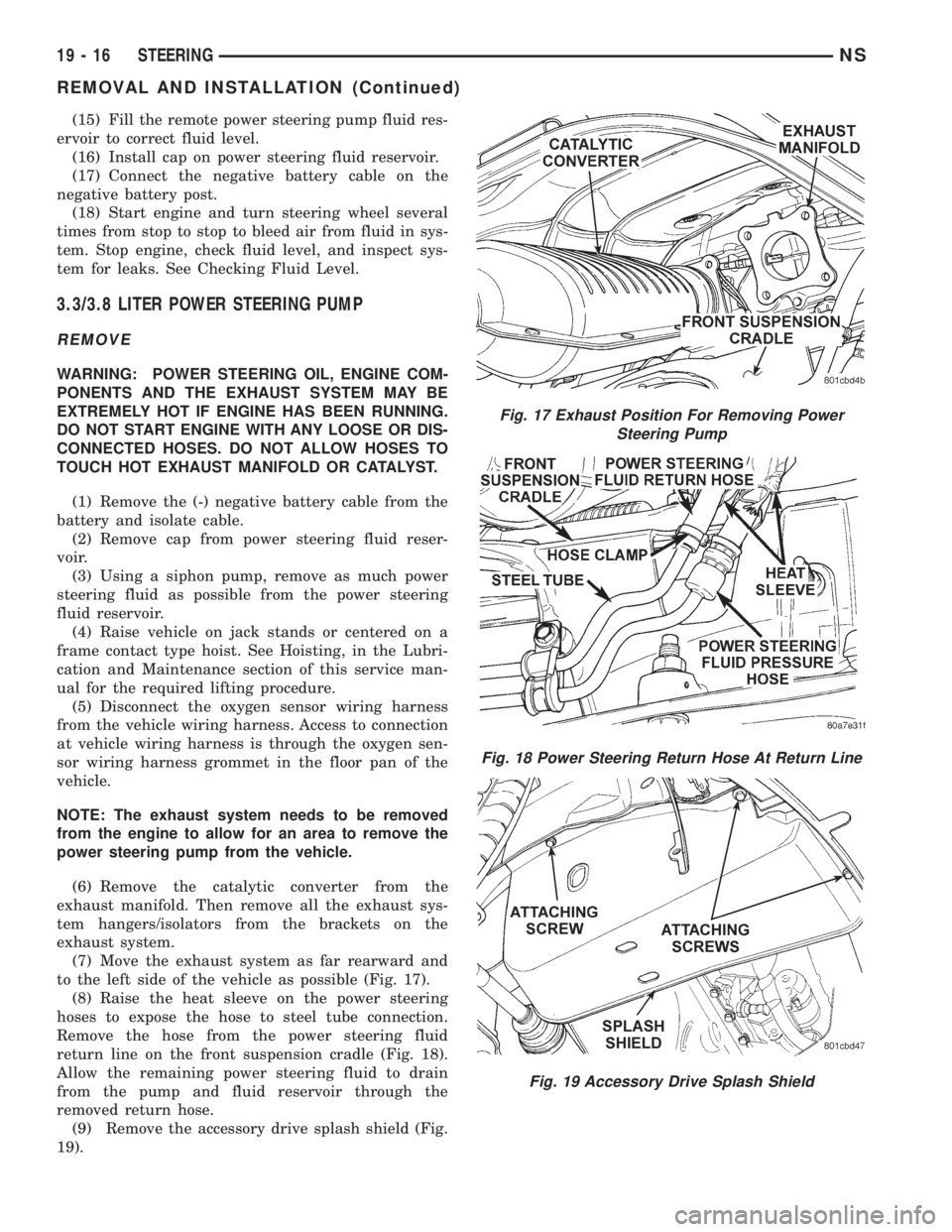
(7) Move the exhaust system as far rearward and
to the left side of the vehicle as possible (Fig. 17).
(8) Raise the heat sleeve on the power steering
hoses to expose the hose to steel tube connection.
Remove the hose from the power steering fluid
return line on the front suspension cradle (Fig. 18).
Allow the remaining power steering fluid to drain
from the pump and fluid reservoir through the
removed return hose.
(9) Remove the accessory drive splash shield (Fig.
19).
Fig. 17 Exhaust Position For Removing Power
Steering Pump
Fig. 18 Power Steering Return Hose At Return Line
Fig. 19 Accessory Drive Splash Shield
19 - 16 STEERINGNS
REMOVAL AND INSTALLATION (Continued)
Page 1478 of 1938
GEARSHIFT AND PARKING LOCK CONTROLS
The transaxle is controlled by a lever type gear-
shift incorporated within the steering column. The
control has six selector lever positions: P (park), R
(reverse), N (neutral), and D (drive), 2 (second), and
1 (first). The parking lock is applied by moving the
selector lever past a gate to the P position.Do not
apply the parking lock until the vehicle has
stopped; otherwise, a severe ratchet noise will
occur.
TORQUE CONVERTER CLUTCH SOLENOID WIRING
CONNECTOR
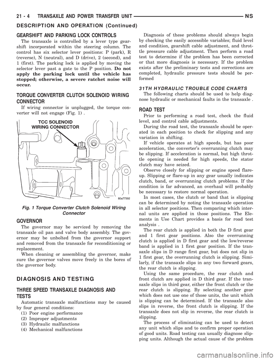
If wiring connector is unplugged, the torque con-
verter will not engage (Fig. 1) .
GOVERNOR
The governor may be serviced by removing the
transaxle oil pan and valve body assembly. The gov-
ernor may be unbolted from the governor support
and removed from the transaxle for reconditioning or
replacement.
When cleaning or assembling the governor, make
sure the governor valves move freely in the bores of
the governor body.
DIAGNOSIS AND TESTING
THREE SPEED TRANSAXLE DIAGNOSIS AND
TESTS
Automatic transaxle malfunctions may be caused
by four general conditions:
(1) Poor engine performance
(2) Improper adjustments
(3) Hydraulic malfunctions
(4) Mechanical malfunctionsDiagnosis of these problems should always begin
by checking the easily accessible variables; fluid level
and condition, gearshift cable adjustment, and throt-
tle pressure cable adjustment. Then perform a road
test to determine if the problem has been corrected
or that more diagnosis is necessary. If the problem
exists after the preliminary tests and corrections are
completed, hydraulic pressure tests should be per-
formed
31TH HYDRAULIC TROUBLE CODE CHARTS
The following charts should be used to help diag-
nose hydraulic or mechanical faults in the transaxle .
ROAD TEST
Prior to performing a road test, check the fluid
level, and control cable adjustments.
During the road test, the transaxle should be oper-
ated in each position to check for slipping and any
variation in shifting.
If vehicle operates at high speeds, but has poor
acceleration, the converter's overrunning clutch may
be slipping. If acceleration is normal, but high throt-
tle opening is needed for high speeds, the stator
clutch may have seized.
Observe closely for slipping or engine speed flare-
up. Slipping or flare-up in any gear usually indicates
clutch, band, or overrunning clutch problems. If the
condition is far advanced, an overhaul will probably
be necessary to restore normal operation.
In most cases, the clutch or band that is slipping
can be determined by noting the transaxle operation
in all selector positions. Then comparing which inter-
nal units are applied in those positions. The Ele-
ments in Use Chart provides a basis for road test
analysis .
The rear clutch is applied in both the D first gear
and 1 first gear positions. Also the overrunning
clutch is applied in D first gear and the low/reverse
band is applied in 1 first gear position. If the tran-
saxle slips in D range first gear, but does not slip in
1 first gear, the overrunning clutch is slipping. Simi-
larly, if the transaxle slips in any two forward gears,
the rear clutch is slipping.
Using the same procedure, the rear clutch and
front clutch are applied in D third gear. If the tran-
saxle slips in third gear, either the front clutch or the
rear clutch is slipping. By selecting another gear
which does not use one of those units, the unit which
is slipping can be determined. If the transaxle also
slips in reverse, the front clutch is slipping. If the
transaxle does not slip in reverse, the rear clutch is
slipping.
The process of eliminating can be used to detect
any unit which slips and to confirm proper operation
of good units. Road testing can usually diagnose slip-
ping units. Although the actual cause of the problem
Fig. 1 Torque Converter Clutch Solenoid Wiring
Connector
21 - 4 TRANSAXLE AND POWER TRANSFER UNITNS
DESCRIPTION AND OPERATION (Continued)
Page 1616 of 1938
(2) Using Miller Special Tool 5052 and C-4171,
install differential bearing to differential (bearing
retainer side).
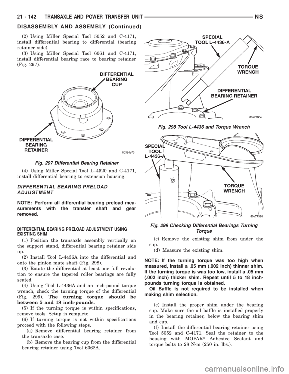
(3) Using Miller Special Tool 6061 and C-4171,
install differential bearing race to bearing retainer
(Fig. 297).
(4) Using Miller Special Tool L±4520 and C-4171,
install differential bearing to extension housing.
DIFFERENTIAL BEARING PRELOAD
ADJUSTMENT
NOTE: Perform all differential bearing preload mea-
surements with the transfer shaft and gear
removed.
DIFFERENTIAL BEARING PRELOAD ADJUSTMENT USING
EXISTING SHIM
(1) Position the transaxle assembly vertically on
the support stand, differential bearing retainer side
up.
(2) Install Tool L-4436A into the differential and
onto the pinion mate shaft (Fig. 298).
(3) Rotate the differential at least one full revolu-
tion to ensure the tapered roller bearings are fully
seated.
(4) Using Tool L-4436A and an inch-pound torque
wrench, check the turning torque of the differential
(Fig. 299).The turning torque should be
between 5 and 18 inch-pounds.
(5) If the turning torque is within specifications,
remove tools. Setup is complete.
(6) If turning torque is not within specifications
proceed with the following steps.
(a) Remove differential bearing retainer from
the transaxle case.
(b) Remove the bearing cup from the differential
bearing retainer using Tool 6062A.(c) Remove the existing shim from under the
cup.
(d) Measure the existing shim.
NOTE: If the turning torque was too high when
measured, install a .05 mm (.002 inch) thinner shim.
If the turning torque is was too low, install a .05 mm
(.002 inch) thicker shim. Repeat until 5 to 18 inch-
pounds turning torque is obtained.
Oil Baffle is not required to be installed when
making shim selection.
(e) Install the proper shim under the bearing
cup. Make sure the oil baffle is installed properly
in the bearing retainer, below the bearing shim
and cup.
(f) Install the differential bearing retainer using
Tool 5052 and C-4171. Seal the retainer to the
housing with MOPARtAdhesive Sealant and
torque bolts to 28 N´m (250 in. lbs.).
Fig. 297 Differential Bearing Retainer
Fig. 298 Tool L-4436 and Torque Wrench
Fig. 299 Checking Differential Bearings Turning
Torque
21 - 142 TRANSAXLE AND POWER TRANSFER UNITNS
DISASSEMBLY AND ASSEMBLY (Continued)