1996 CHRYSLER VOYAGER checking oil
[x] Cancel search: checking oilPage 1172 of 1938
(2) If new core plugs are installed, see Engine Core
Oil and Cam Plugs.
(3) Examine block for cracks or fractures.
CYLINDER BORE INSPECTION
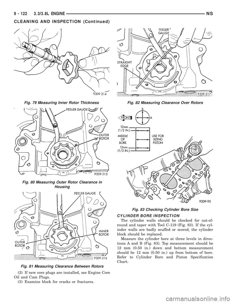
The cylinder walls should be checked for out-of-
round and taper with Tool C-119 (Fig. 83). If the cyl-
inder walls are badly scuffed or scored, the cylinder
block should be replaced.
Measure the cylinder bore at three levels in direc-
tions A and B (Fig. 83). Top measurement should be
12 mm (0.50 in.) down and bottom measurement
should be 12 mm (0.50 in.) up from bottom of bore.
Refer to Cylinder Bore and Piston Specification
Chart.
Fig. 79 Measuring Inner Rotor Thickness
Fig. 80 Measuring Outer Rotor Clearance in
Housing
Fig. 81 Measuring Clearance Between Rotors
Fig. 82 Measuring Clearance Over Rotors
Fig. 83 Checking Cylinder Bore Size
9 - 122 3.3/3.8L ENGINENS
CLEANING AND INSPECTION (Continued)
Page 1179 of 1938
ENGINE
CONTENTS
page page
2.0L SOHC ENGINE...................... 12.5L VM DIESEL....................... 40
2.0L SOHC ENGINE
INDEX
page page
DESCRIPTION AND OPERATION
ENGINE COMPONENTS.................. 3
ENGINE IDENTIFICATION................. 1
ENGINE LUBRICATION SYSTEM............ 2
GENERAL SPECIFICATION................ 2
DIAGNOSIS AND TESTING
CHECKING ENGINE OIL PRESSURE........ 3
SERVICE PROCEDURES
CRANKSHAFT END PLAY................. 6
CYLINDER BORE AND PISTON SIZING....... 4
FITTING CONNECTING RODS.............. 5
FITTING CRANKSHAFT BEARINGS.......... 6
FITTING PISTON RINGS.................. 4
REMOVAL AND INSTALLATION
CAMSHAFT OIL SEAL................... 12
CAMSHAFT............................ 7
CRANKSHAFT OIL SEALÐREAR........... 20
CRANKSHAFT......................... 21
CYLINDER HEAD COVER................. 6
CYLINDER HEAD....................... 10
FRONT CRANKSHAFT OIL SEAL........... 18
OILFILTER ........................... 24
OIL FILTER ADAPTER................... 24OILPAN .............................. 17
OIL PUMP............................ 25
PISTON AND CONNECTING ROD.......... 25
ROCKER ARM/HYDRAULIC LASH ADJUSTER . . 8
SPARK PLUG TUBE...................... 7
TIMING BELT COVER................... 11
TIMING BELT SYSTEM.................. 13
VALVE SEALS AND SPRINGS IN VEHICLE . . . 10
VIBRATION DAMPER.................... 28
DISASSEMBLY AND ASSEMBLY
OIL PUMP............................ 29
VALVE SERVICE WITH THE CYLINDER HEAD
REMOVED.......................... 29
CLEANING AND INSPECTION
CYLINDER BLOCK AND BORE............ 34
CYLINDER HEAD AND CAMSHAFT
JOURNALS.......................... 32
OIL PUMP............................ 32
SPECIFICATIONS
ENGINE 2.0L SOHC..................... 34
TORQUE CHART 2.0L SOHC.............. 36
SPECIAL TOOLS
ENGINE 2.0L SOHC..................... 36
DESCRIPTION AND OPERATION
ENGINE IDENTIFICATION
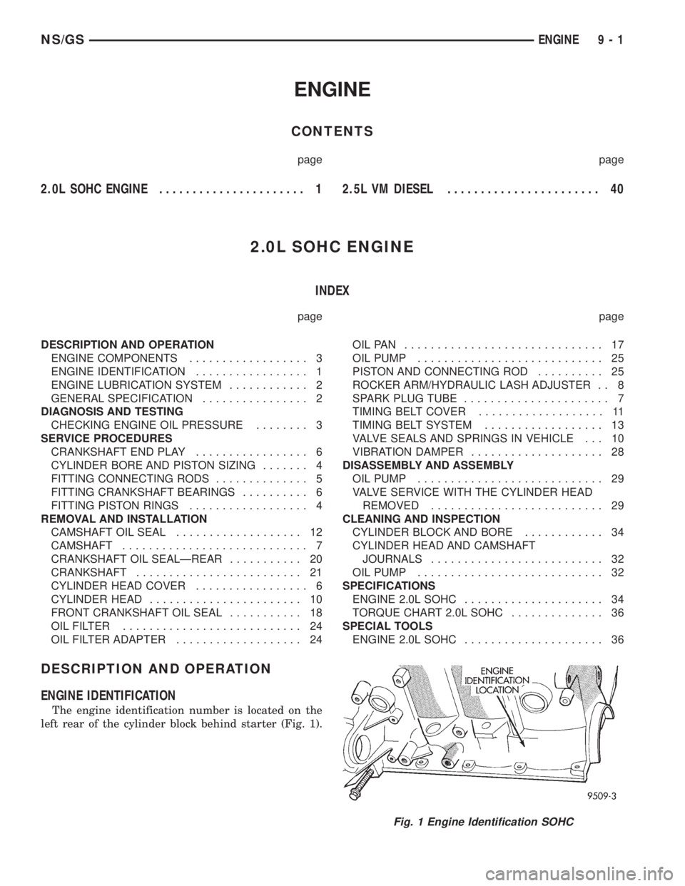
The engine identification number is located on the
left rear of the cylinder block behind starter (Fig. 1).
Fig. 1 Engine Identification SOHC
NS/GSENGINE 9 - 1
Page 1181 of 1938
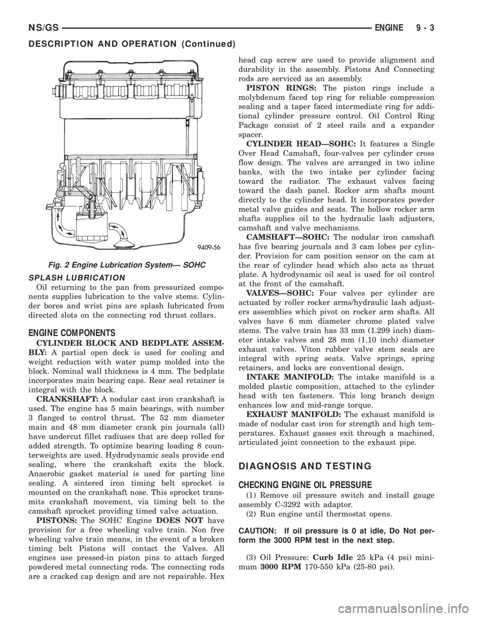
SPLASH LUBRICATION
Oil returning to the pan from pressurized compo-
nents supplies lubrication to the valve stems. Cylin-
der bores and wrist pins are splash lubricated from
directed slots on the connecting rod thrust collars.
ENGINE COMPONENTS
CYLINDER BLOCK AND BEDPLATE ASSEM-
B LY:A partial open deck is used for cooling and
weight reduction with water pump molded into the
block. Nominal wall thickness is 4 mm. The bedplate
incorporates main bearing caps. Rear seal retainer is
integral with the block.
CRANKSHAFT:A nodular cast iron crankshaft is
used. The engine has 5 main bearings, with number
3 flanged to control thrust. The 52 mm diameter
main and 48 mm diameter crank pin journals (all)
have undercut fillet radiuses that are deep rolled for
added strength. To optimize bearing loading 8 coun-
terweights are used. Hydrodynamic seals provide end
sealing, where the crankshaft exits the block.
Anaerobic gasket material is used for parting line
sealing. A sintered iron timing belt sprocket is
mounted on the crankshaft nose. This sprocket trans-
mits crankshaft movement, via timing belt to the
camshaft sprocket providing timed valve actuation.
PISTONS:The SOHC EngineDOES NOThave
provision for a free wheeling valve train. Non free
wheeling valve train means, in the event of a broken
timing belt Pistons will contact the Valves. All
engines use pressed-in piston pins to attach forged
powdered metal connecting rods. The connecting rods
are a cracked cap design and are not repairable. Hexhead cap screw are used to provide alignment and
durability in the assembly. Pistons And Connecting
rods are serviced as an assembly.
PISTON RINGS:The piston rings include a
molybdenum faced top ring for reliable compression
sealing and a taper faced intermediate ring for addi-
tional cylinder pressure control. Oil Control Ring
Package consist of 2 steel rails and a expander
spacer.
CYLINDER HEADÐSOHC:It features a Single
Over Head Camshaft, four-valves per cylinder cross
flow design. The valves are arranged in two inline
banks, with the two intake per cylinder facing
toward the radiator. The exhaust valves facing
toward the dash panel. Rocker arm shafts mount
directly to the cylinder head. It incorporates powder
metal valve guides and seats. The hollow rocker arm
shafts supplies oil to the hydraulic lash adjusters,
camshaft and valve mechanisms.
CAMSHAFTÐSOHC:The nodular iron camshaft
has five bearing journals and 3 cam lobes per cylin-
der. Provision for cam position sensor on the cam at
the rear of cylinder head which also acts as thrust
plate. A hydrodynamic oil seal is used for oil control
at the front of the camshaft.
VALVESÐSOHC:Four valves per cylinder are
actuated by roller rocker arms/hydraulic lash adjust-
ers assemblies which pivot on rocker arm shafts. All
valves have 6 mm diameter chrome plated valve
stems. The valve train has 33 mm (1.299 inch) diam-
eter intake valves and 28 mm (1.10 inch) diameter
exhaust valves. Viton rubber valve stem seals are
integral with spring seats. Valve springs, spring
retainers, and locks are conventional design.
INTAKE MANIFOLD:The intake manifold is a
molded plastic composition, attached to the cylinder
head with ten fasteners. This long branch design
enhances low and mid-range torque.
EXHAUST MANIFOLD:The exhaust manifold is
made of nodular cast iron for strength and high tem-
peratures. Exhaust gasses exit through a machined,
articulated joint connection to the exhaust pipe.
DIAGNOSIS AND TESTING
CHECKING ENGINE OIL PRESSURE
(1) Remove oil pressure switch and install gauge
assembly C-3292 with adaptor.
(2) Run engine until thermostat opens.
CAUTION: If oil pressure is 0 at idle, Do Not per-
form the 3000 RPM test in the next step.
(3) Oil Pressure:Curb Idle25 kPa (4 psi) mini-
mum3000 RPM170-550 kPa (25-80 psi).
Fig. 2 Engine Lubrication SystemÐ SOHC
NS/GSENGINE 9 - 3
DESCRIPTION AND OPERATION (Continued)
Page 1182 of 1938
(4) If oil pressure is 0 at idle. Shut off engine,
check for pressure relief valve stuck open, a clogged
oil pick-up screen or a damaged oil pick-up tube
O-ring.
SERVICE PROCEDURES
CYLINDER BORE AND PISTON SIZING
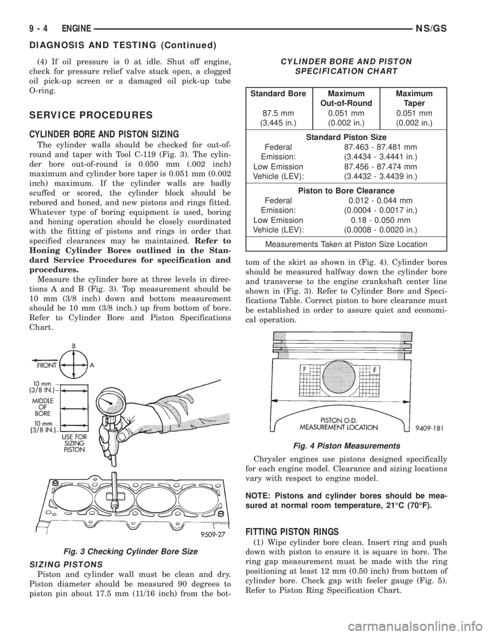
The cylinder walls should be checked for out-of-
round and taper with Tool C-119 (Fig. 3). The cylin-
der bore out-of-round is 0.050 mm (.002 inch)
maximum and cylinder bore taper is 0.051 mm (0.002
inch) maximum. If the cylinder walls are badly
scuffed or scored, the cylinder block should be
rebored and honed, and new pistons and rings fitted.
Whatever type of boring equipment is used, boring
and honing operation should be closely coordinated
with the fitting of pistons and rings in order that
specified clearances may be maintained.Refer to
Honing Cylinder Bores outlined in the Stan-
dard Service Procedures for specification and
procedures.
Measure the cylinder bore at three levels in direc-
tions A and B (Fig. 3). Top measurement should be
10 mm (3/8 inch) down and bottom measurement
should be 10 mm (3/8 inch.) up from bottom of bore.
Refer to Cylinder Bore and Piston Specifications
Chart.
SIZING PISTONS
Piston and cylinder wall must be clean and dry.
Piston diameter should be measured 90 degrees to
piston pin about 17.5 mm (11/16 inch) from the bot-tom of the skirt as shown in (Fig. 4). Cylinder bores
should be measured halfway down the cylinder bore
and transverse to the engine crankshaft center line
shown in (Fig. 3). Refer to Cylinder Bore and Speci-
fications Table. Correct piston to bore clearance must
be established in order to assure quiet and economi-
cal operation.
Chrysler engines use pistons designed specifically
for each engine model. Clearance and sizing locations
vary with respect to engine model.
NOTE: Pistons and cylinder bores should be mea-
sured at normal room temperature, 21ÉC (70ÉF).
FITTING PISTON RINGS
(1) Wipe cylinder bore clean. Insert ring and push
down with piston to ensure it is square in bore. The
ring gap measurement must be made with the ring
positioning at least 12 mm (0.50 inch) from bottom of
cylinder bore. Check gap with feeler gauge (Fig. 5).
Refer to Piston Ring Specification Chart.
Fig. 3 Checking Cylinder Bore Size
CYLINDER BORE AND PISTON
SPECIFICATION CHART
Standard Bore Maximum
Out-of-RoundMaximum
Taper
87.5 mm
(3.445 in.)0.051 mm
(0.002 in.)0.051 mm
(0.002 in.)
Standard Piston Size
Federal
Emission:87.463 - 87.481 mm
(3.4434 - 3.4441 in.)
Low Emission
Vehicle (LEV):87.456 - 87.474 mm
(3.4432 - 3.4439 in.)
Piston to Bore Clearance
Federal
Emission:0.012 - 0.044 mm
(0.0004 - 0.0017 in.)
Low Emission
Vehicle (LEV):0.18 - 0.050 mm
(0.0008 - 0.0020 in.)
Measurements Taken at Piston Size Location
Fig. 4 Piston Measurements
9 - 4 ENGINENS/GS
DIAGNOSIS AND TESTING (Continued)
Page 1184 of 1938
FITTING CRANKSHAFT BEARINGS
Refer to Measuring Main Bearing Clearance in
Standard Service Procedures. Refer to Crankshaft
Specification Chart for specifications.
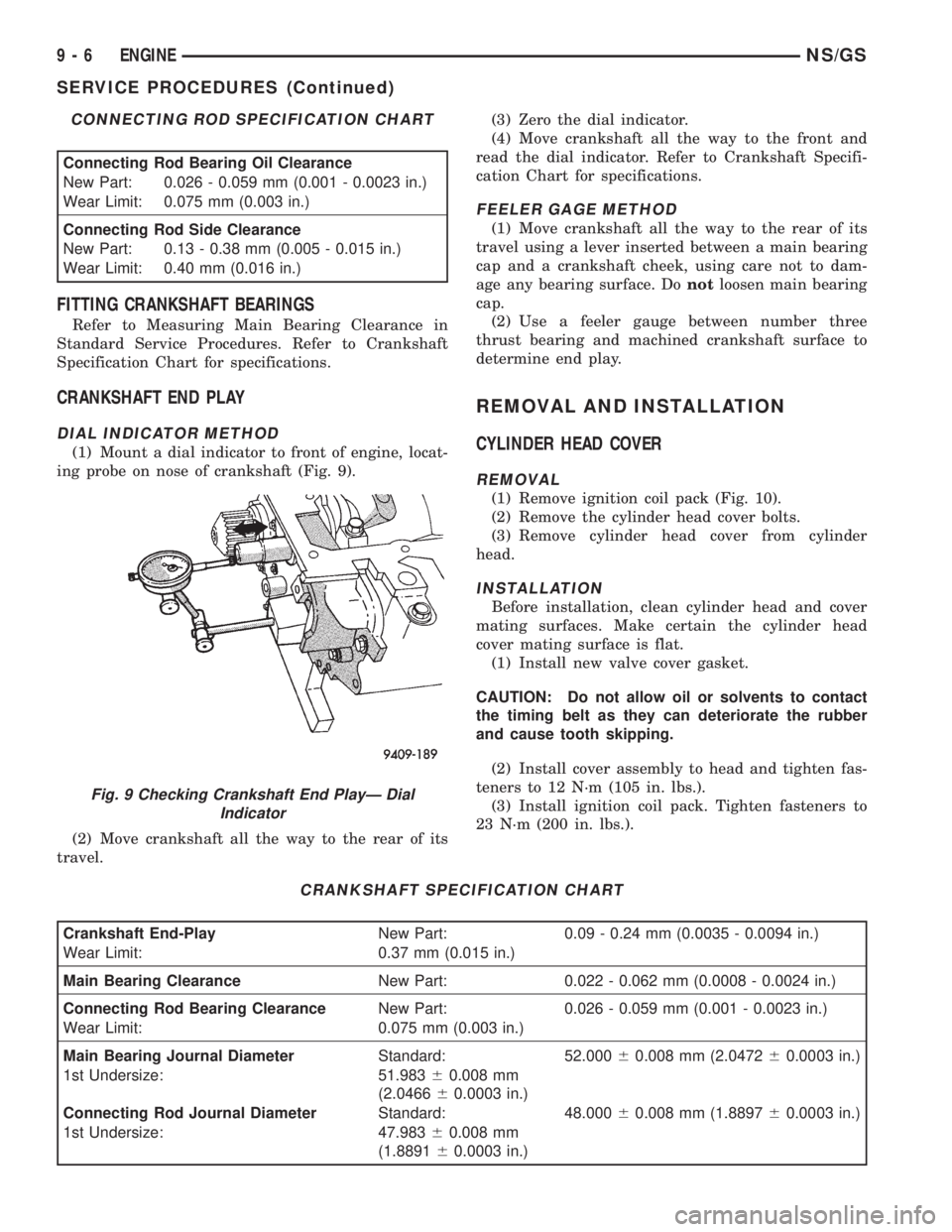
CRANKSHAFT END PLAY
DIAL INDICATOR METHOD
(1) Mount a dial indicator to front of engine, locat-
ing probe on nose of crankshaft (Fig. 9).
(2) Move crankshaft all the way to the rear of its
travel.(3) Zero the dial indicator.
(4) Move crankshaft all the way to the front and
read the dial indicator. Refer to Crankshaft Specifi-
cation Chart for specifications.
FEELER GAGE METHOD
(1) Move crankshaft all the way to the rear of its
travel using a lever inserted between a main bearing
cap and a crankshaft cheek, using care not to dam-
age any bearing surface. Donotloosen main bearing
cap.
(2) Use a feeler gauge between number three
thrust bearing and machined crankshaft surface to
determine end play.
REMOVAL AND INSTALLATION
CYLINDER HEAD COVER
REMOVAL
(1) Remove ignition coil pack (Fig. 10).
(2) Remove the cylinder head cover bolts.
(3) Remove cylinder head cover from cylinder
head.
INSTALLATION
Before installation, clean cylinder head and cover
mating surfaces. Make certain the cylinder head
cover mating surface is flat.
(1) Install new valve cover gasket.
CAUTION: Do not allow oil or solvents to contact
the timing belt as they can deteriorate the rubber
and cause tooth skipping.
(2) Install cover assembly to head and tighten fas-
teners to 12 N´m (105 in. lbs.).
(3) Install ignition coil pack. Tighten fasteners to
23 N´m (200 in. lbs.).
CONNECTING ROD SPECIFICATION CHART
Connecting Rod Bearing Oil Clearance
New Part: 0.026 - 0.059 mm (0.001 - 0.0023 in.)
Wear Limit: 0.075 mm (0.003 in.)
Connecting Rod Side Clearance
New Part: 0.13 - 0.38 mm (0.005 - 0.015 in.)
Wear Limit: 0.40 mm (0.016 in.)
CRANKSHAFT SPECIFICATION CHART
Crankshaft End-PlayNew Part: 0.09 - 0.24 mm (0.0035 - 0.0094 in.)
Wear Limit: 0.37 mm (0.015 in.)
Main Bearing ClearanceNew Part: 0.022 - 0.062 mm (0.0008 - 0.0024 in.)
Connecting Rod Bearing ClearanceNew Part: 0.026 - 0.059 mm (0.001 - 0.0023 in.)
Wear Limit: 0.075 mm (0.003 in.)
Main Bearing Journal DiameterStandard: 52.00060.008 mm (2.047260.0003 in.)
1st Undersize: 51.98360.008 mm
(2.046660.0003 in.)
Connecting Rod Journal DiameterStandard: 48.00060.008 mm (1.889760.0003 in.)
1st Undersize: 47.98360.008 mm
(1.889160.0003 in.)
Fig. 9 Checking Crankshaft End PlayÐ Dial
Indicator
9 - 6 ENGINENS/GS
SERVICE PROCEDURES (Continued)
Page 1189 of 1938
(13) Remove timing belt and camshaft sprocket.
Refer to procedure outlined in this section.
(14) Remove rocker arm shaft assemblies.
(15) Remove cylinder head bolts.
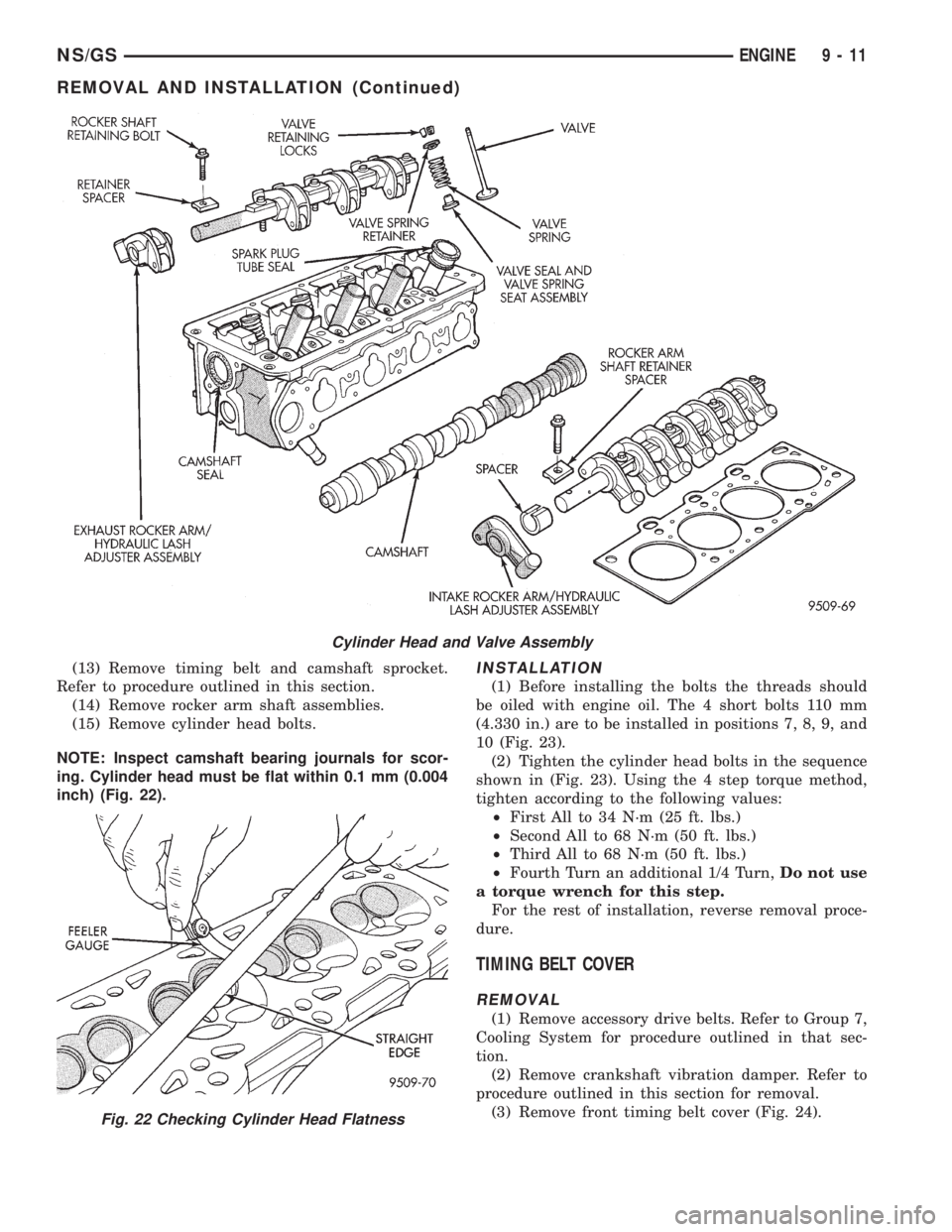
NOTE: Inspect camshaft bearing journals for scor-
ing. Cylinder head must be flat within 0.1 mm (0.004
inch) (Fig. 22).INSTALLATION
(1) Before installing the bolts the threads should
be oiled with engine oil. The 4 short bolts 110 mm
(4.330 in.) are to be installed in positions 7, 8, 9, and
10 (Fig. 23).
(2) Tighten the cylinder head bolts in the sequence
shown in (Fig. 23). Using the 4 step torque method,
tighten according to the following values:
²First All to 34 N´m (25 ft. lbs.)
²Second All to 68 N´m (50 ft. lbs.)
²Third All to 68 N´m (50 ft. lbs.)
²Fourth Turn an additional 1/4 Turn,Do not use
a torque wrench for this step.
For the rest of installation, reverse removal proce-
dure.
TIMING BELT COVER
REMOVAL
(1) Remove accessory drive belts. Refer to Group 7,
Cooling System for procedure outlined in that sec-
tion.
(2) Remove crankshaft vibration damper. Refer to
procedure outlined in this section for removal.
(3) Remove front timing belt cover (Fig. 24).
Cylinder Head and Valve Assembly
Fig. 22 Checking Cylinder Head Flatness
NS/GSENGINE 9 - 11
REMOVAL AND INSTALLATION (Continued)
Page 1194 of 1938
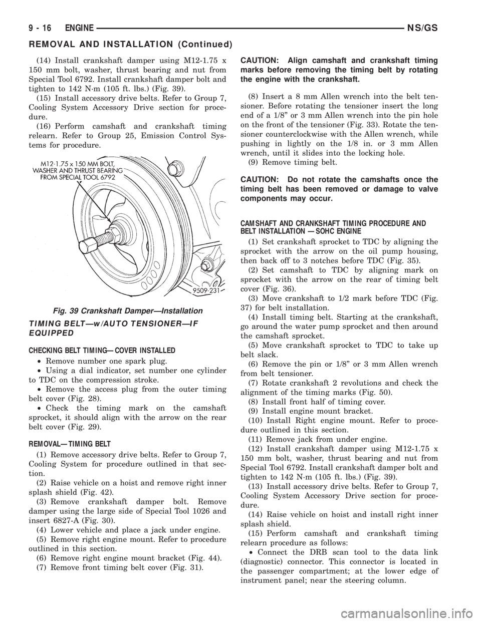
(14) Install crankshaft damper using M12-1.75 x
150 mm bolt, washer, thrust bearing and nut from
Special Tool 6792. Install crankshaft damper bolt and
tighten to 142 N´m (105 ft. lbs.) (Fig. 39).
(15) Install accessory drive belts. Refer to Group 7,
Cooling System Accessory Drive section for proce-
dure.
(16) Perform camshaft and crankshaft timing
relearn. Refer to Group 25, Emission Control Sys-
tems for procedure.
TIMING BELTÐw/AUTO TENSIONERÐIF
EQUIPPED
CHECKING BELT TIMINGÐCOVER INSTALLED
²Remove number one spark plug.
²Using a dial indicator, set number one cylinder
to TDC on the compression stroke.
²Remove the access plug from the outer timing
belt cover (Fig. 28).
²Check the timing mark on the camshaft
sprocket, it should align with the arrow on the rear
belt cover (Fig. 29).
REMOVALÐTIMING BELT
(1) Remove accessory drive belts. Refer to Group 7,
Cooling System for procedure outlined in that sec-
tion.
(2) Raise vehicle on a hoist and remove right inner
splash shield (Fig. 42).
(3) Remove crankshaft damper bolt. Remove
damper using the large side of Special Tool 1026 and
insert 6827-A (Fig. 30).
(4) Lower vehicle and place a jack under engine.
(5) Remove right engine mount. Refer to procedure
outlined in this section.
(6) Remove right engine mount bracket (Fig. 44).
(7) Remove front timing belt cover (Fig. 31).CAUTION: Align camshaft and crankshaft timing
marks before removing the timing belt by rotating
the engine with the crankshaft.
(8) Inserta8mmAllen wrench into the belt ten-
sioner. Before rotating the tensioner insert the long
end of a 1/8º or 3 mm Allen wrench into the pin hole
on the front of the tensioner (Fig. 33). Rotate the ten-
sioner counterclockwise with the Allen wrench, while
pushing in lightly on the 1/8 in. or 3 mm Allen
wrench, until it slides into the locking hole.
(9) Remove timing belt.
CAUTION: Do not rotate the camshafts once the
timing belt has been removed or damage to valve
components may occur.
CAMSHAFT AND CRANKSHAFT TIMING PROCEDURE AND
BELT INSTALLATION ÐSOHC ENGINE
(1) Set crankshaft sprocket to TDC by aligning the
sprocket with the arrow on the oil pump housing,
then back off to 3 notches before TDC (Fig. 35).
(2) Set camshaft to TDC by aligning mark on
sprocket with the arrow on the rear of timing belt
cover (Fig. 36).
(3) Move crankshaft to 1/2 mark before TDC (Fig.
37) for belt installation.
(4) Install timing belt. Starting at the crankshaft,
go around the water pump sprocket and then around
the camshaft sprocket.
(5) Move crankshaft sprocket to TDC to take up
belt slack.
(6) Remove the pin or 1/8º or 3 mm Allen wrench
from belt tensioner.
(7) Rotate crankshaft 2 revolutions and check the
alignment of the timing marks (Fig. 50).
(8) Install front half of timing cover.
(9) Install engine mount bracket.
(10) Install Right engine mount. Refer to proce-
dure outlined in this section.
(11) Remove jack from under engine.
(12) Install crankshaft damper using M12-1.75 x
150 mm bolt, washer, thrust bearing and nut from
Special Tool 6792. Install crankshaft damper bolt and
tighten to 142 N´m (105 ft. lbs.) (Fig. 39).
(13) Install accessory drive belts. Refer to Group 7,
Cooling System Accessory Drive section for proce-
dure.
(14) Raise vehicle on hoist and install right inner
splash shield.
(15) Perform camshaft and crankshaft timing
relearn procedure as follows:
²Connect the DRB scan tool to the data link
(diagnostic) connector. This connector is located in
the passenger compartment; at the lower edge of
instrument panel; near the steering column.
Fig. 39 Crankshaft DamperÐInstallation
9 - 16 ENGINENS/GS
REMOVAL AND INSTALLATION (Continued)
Page 1210 of 1938
CAUTION: When depressing the valve spring
retainers with valve spring compressor the locks
can become dislocated. Check to make sure both
locks are in their correct location after removing
tool.
(4) Check the valve spring installed height B after
refacing the valve and seat (Fig. 92). Make sure mea-
surements are taken from top of spring seat to the
bottom surface of spring retainer. If height is greater
than 40.18 mm (1.58 in.), install a 0.762 mm (0.030
in.) spacer under the valve spring seat to bring
spring height back within specification.
(5) Install rocker arm shafts as previously
described in this section.
(6) Checking dry lash. Dry lash is the amount of
clearance that exists between the base circle of an
installed cam and the rocker arm roller when the
adjuster is drained of oil and completely collapsed.
Specified dry lash is 1.17 mm (0.046 in.) for intake
and 1.28 mm (0.050 in.) for exhaust. After performing
dry lash check, refill adjuster with oil and allow 10
minutes for adjuster/s to bleed down before rotating
cam.
CLEANING AND INSPECTION
CYLINDER HEAD AND CAMSHAFT JOURNALS
INSPECTING CYLINDER HEAD
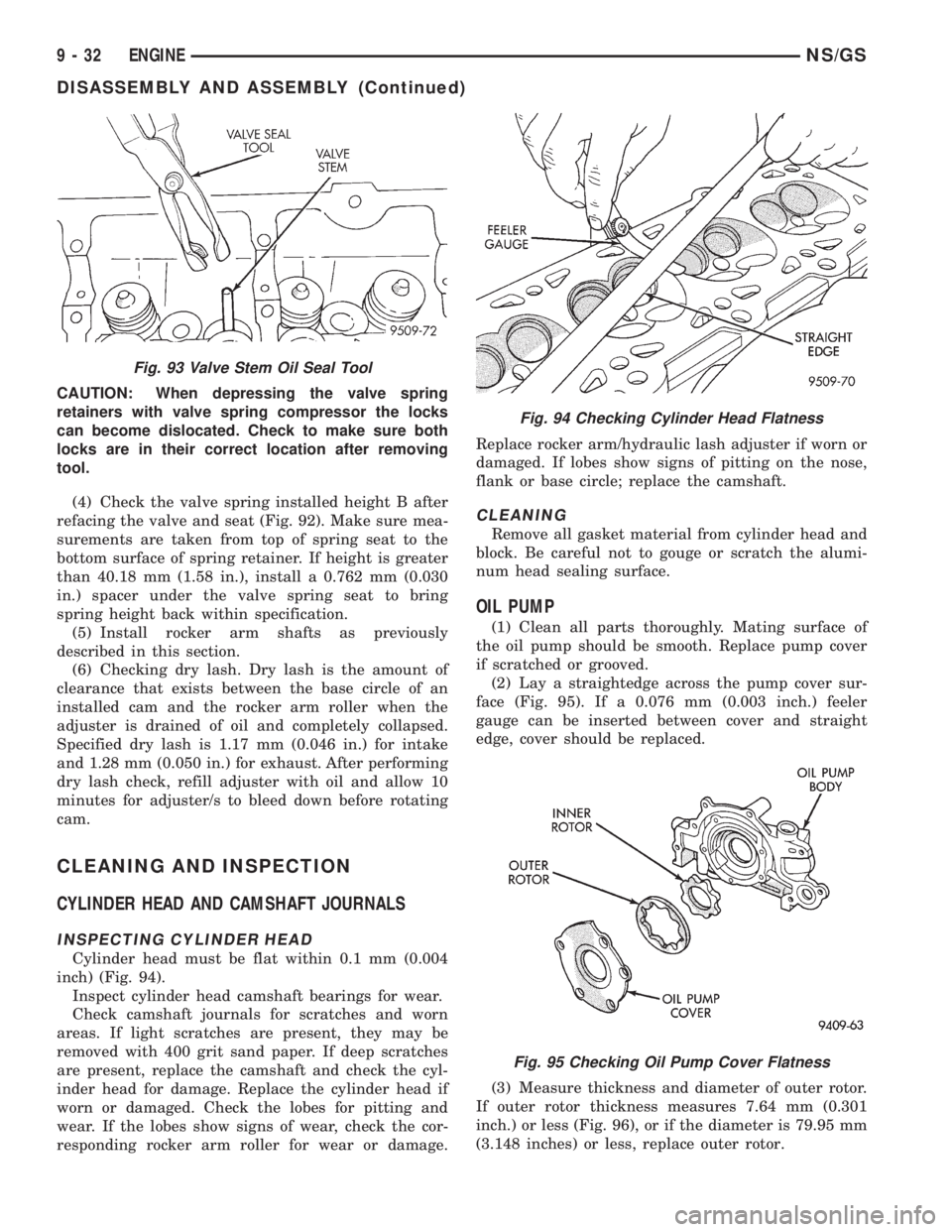
Cylinder head must be flat within 0.1 mm (0.004
inch) (Fig. 94).
Inspect cylinder head camshaft bearings for wear.
Check camshaft journals for scratches and worn
areas. If light scratches are present, they may be
removed with 400 grit sand paper. If deep scratches
are present, replace the camshaft and check the cyl-
inder head for damage. Replace the cylinder head if
worn or damaged. Check the lobes for pitting and
wear. If the lobes show signs of wear, check the cor-
responding rocker arm roller for wear or damage.Replace rocker arm/hydraulic lash adjuster if worn or
damaged. If lobes show signs of pitting on the nose,
flank or base circle; replace the camshaft.
CLEANING
Remove all gasket material from cylinder head and
block. Be careful not to gouge or scratch the alumi-
num head sealing surface.
OIL PUMP
(1) Clean all parts thoroughly. Mating surface of
the oil pump should be smooth. Replace pump cover
if scratched or grooved.
(2) Lay a straightedge across the pump cover sur-
face (Fig. 95). If a 0.076 mm (0.003 inch.) feeler
gauge can be inserted between cover and straight
edge, cover should be replaced.
(3) Measure thickness and diameter of outer rotor.
If outer rotor thickness measures 7.64 mm (0.301
inch.) or less (Fig. 96), or if the diameter is 79.95 mm
(3.148 inches) or less, replace outer rotor.
Fig. 93 Valve Stem Oil Seal Tool
Fig. 94 Checking Cylinder Head Flatness
Fig. 95 Checking Oil Pump Cover Flatness
9 - 32 ENGINENS/GS
DISASSEMBLY AND ASSEMBLY (Continued)