1996 CHRYSLER VOYAGER checking oil
[x] Cancel search: checking oilPage 1055 of 1938
CAUTION: Be sure that the tapped holes maintain
the original centerline.
Heli-Coil tools and inserts are readily available
from automotive parts jobbers.
HYDROSTATIC LOCKED ENGINE
When an engine is suspected to be hydrostatically
locked, regardless of what caused the problem, these
steps should be used.
CAUTION: Do Not Use Starter Motor To Rotate
Engine, severe damage may occur.
(1) Inspect air cleaner, induction system and
intake manifold to insure system is dry and clear of
foreign material.
(2) Remove negative battery cable.
(3) Place a shop towel around the spark plugs
when removing them from the engine. This will catch
any fluid that may possibly be in the cylinder under
pressure.
(4) With all spark plugs removed, rotate engine
crankshaft using a breaker bar and socket.
(5) Identify the fluid in the cylinder(s) (i.e., cool-
ant, fuel, oil or other).
(6) Make sure all fluid has been removed from the
cylinders. Inspect engine for damage (i.e., Connecting
Rods, Pistons, Valves etc.)
(7) Repair engine or components as necessary to
prevent this problem from occurring again.
CAUTION: Squirt approximately 1 teaspoon of oil
into cylinders, rotate engine to lubricate the cylin-
der walls to prevent damage on restart.
(8) Install new spark plugs.
(9) Drain engine oil and remove oil filter.
(10) Fill engine with specified amount of approved
oil and install new oil filter.
(11) Connect negative battery cable.
(12) Start engine and check for any leaks.
ENGINE OIL
Checking Oil Level
To assure proper engine lubrication, the engine oil
must be maintained at the correct level. Check the
oil level at regular intervals, such as every fuel stop.
The best time to check the oil level is about 5 min-
utes after a fully warmed-up engine is shut off, or
before starting the vehicle after it has sat overnight.
Checking the oil while the vehicle is on level
ground, will improve the accuracy of the oil level
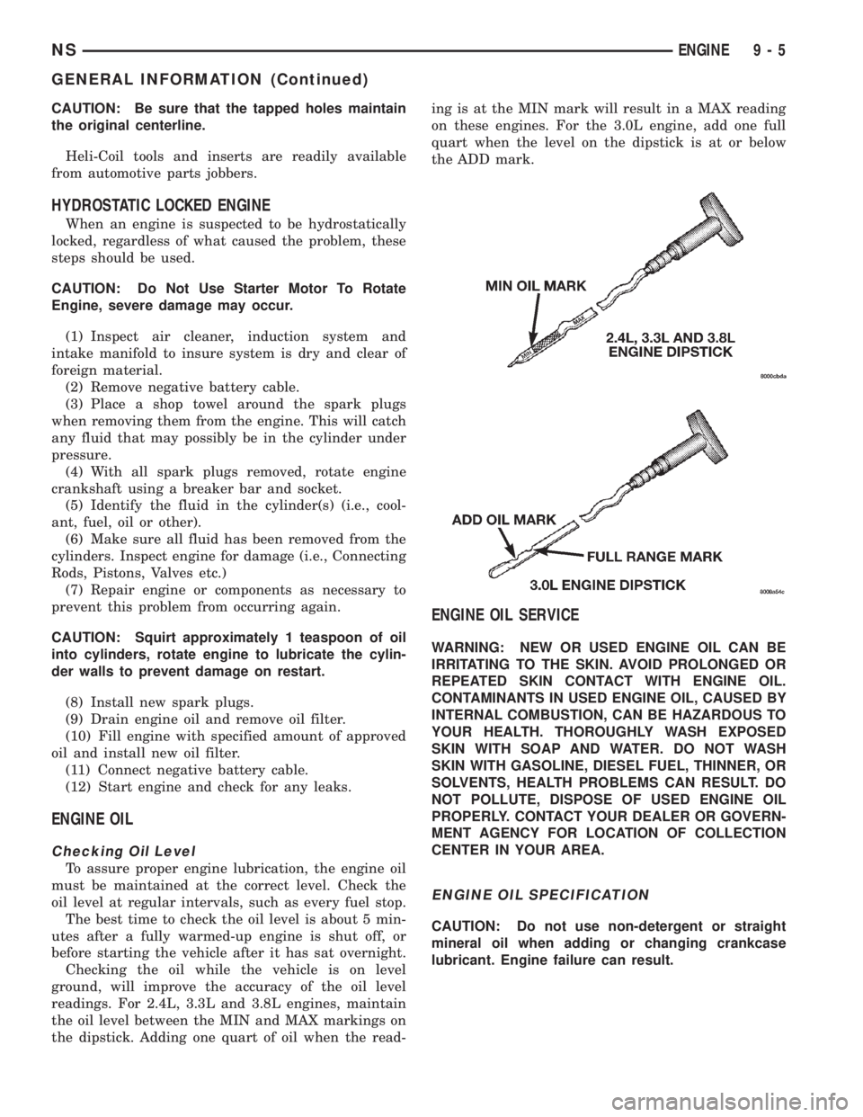
readings. For 2.4L, 3.3L and 3.8L engines, maintain
the oil level between the MIN and MAX markings on
the dipstick. Adding one quart of oil when the read-ing is at the MIN mark will result in a MAX reading
on these engines. For the 3.0L engine, add one full
quart when the level on the dipstick is at or below
the ADD mark.
ENGINE OIL SERVICE
WARNING: NEW OR USED ENGINE OIL CAN BE
IRRITATING TO THE SKIN. AVOID PROLONGED OR
REPEATED SKIN CONTACT WITH ENGINE OIL.
CONTAMINANTS IN USED ENGINE OIL, CAUSED BY
INTERNAL COMBUSTION, CAN BE HAZARDOUS TO
YOUR HEALTH. THOROUGHLY WASH EXPOSED
SKIN WITH SOAP AND WATER. DO NOT WASH
SKIN WITH GASOLINE, DIESEL FUEL, THINNER, OR
SOLVENTS, HEALTH PROBLEMS CAN RESULT. DO
NOT POLLUTE, DISPOSE OF USED ENGINE OIL
PROPERLY. CONTACT YOUR DEALER OR GOVERN-
MENT AGENCY FOR LOCATION OF COLLECTION
CENTER IN YOUR AREA.
ENGINE OIL SPECIFICATION
CAUTION: Do not use non-detergent or straight
mineral oil when adding or changing crankcase
lubricant. Engine failure can result.
NSENGINE 9 - 5
GENERAL INFORMATION (Continued)
Page 1064 of 1938
2.4L ENGINE
INDEX
page page
DESCRIPTION AND OPERATION
ENGINE COMPONENTS.................. 15
ENGINE IDENTIFICATION................. 14
ENGINE LUBRICATION SYSTEM............ 14
DIAGNOSIS AND TESTING
CHECKING ENGINE OIL PRESSURE......... 16
SERVICE PROCEDURES
CRANKSHAFT END PLAY................. 20
FITTING CONNECTING ROD BEARINGS..... 18
FITTING MAIN BEARINGS................. 19
FITTING PISTON RINGS.................. 16
FITTING PISTONS....................... 16
VALVE SERVICE RECONDITION............ 21
REMOVAL AND INSTALLATION
BALANCE SHAFTS CARRIER ASSEMBLY..... 30
CAMSHAFT FOLLOWER.................. 30
CAMSHAFT OIL SEALÐFRONT............. 41
CAMSHAFT............................ 28
CRANKSHAFT OIL SEALÐFRONT........... 42
CRANKSHAFT OIL SEALÐREAR............ 43
CRANKSHAFT.......................... 46
CYLINDER HEAD COVER................. 28
CYLINDER HEAD........................ 34
ENGINE ASSEMBLY...................... 26
ENGINE MOUNTÐFRONT................. 23
ENGINE MOUNTÐLEFT.................. 24
ENGINE MOUNTÐREAR.................. 25
ENGINE MOUNTÐRIGHT................. 24HYDRAULIC LASH ADJUSTER.............. 33
OILFILTER ............................ 47
OILPAN ............................... 45
OIL PUMP............................. 47
PISTON AND CONNECTING ROD........... 49
STRUCTURAL COLLAR................... 25
TIMING BELT COVER.................... 37
TIMING BELT TENSIONER ASSEMBLY....... 40
TIMING BELT........................... 37
VALVE SPRINGS AND
VALVE SEALS IN VEHICLE............... 33
VALVES AND VALVE SPRINGS............. 35
VIBRATION DAMPER.................... 36
DISASSEMBLY AND ASSEMBLY
OIL PUMP............................. 50
CLEANING AND INSPECTION
OIL PUMP............................. 52
CRANKSHAFT.......................... 52
CYLINDER BLOCK....................... 54
CYLINDER HEAD........................ 51
VALVE AND VALVE SPRING................ 51
ADJUSTMENTS
ENGINE MOUNTS....................... 54
SPECIFICATIONS
2.4L ENGINE........................... 55
TORQUE CHART 2.4L.................... 57
SPECIAL TOOLS
2.4L ENGINE........................... 58
DESCRIPTION AND OPERATION
ENGINE IDENTIFICATION
The engine identification number is located on the
rear of the cylinder block (Fig. 1).
ENGINE LUBRICATION SYSTEM
OIL PAN
A structural die cast aluminum oil pan provides
lower engine protection as well as serving as the
engine oil reservoir. Oil pan is attached to block and
sealed with a gasket. The oil pickup tube has a
strainer and cover.
PRESSURE LUBRICATION
Oil drawn up through the pickup tube is pressur-
ized by the pump and routed through the full flow fil-
ter to the main oil gallery running the length of thecylinder block. Oil pickup, pump and check valve pro-
vide oil flow to the main oil gallery.
MAIN/ROD BEARINGS
A diagonal hole in each bulkhead feeds oil to each
main bearing. Drilled passages within the crankshaft
route oil from main bearing journals to connecting
rod journals.
CAMSHAFT/HYDRAULIC LASH ADJUSTERS
A vertical hole at the number five bulkhead routes
pressurized oil through a restrictor up past a cylin-
der head bolt to an oil gallery running the length of
the cylinder head. The camshaft journals are par-
tially slotted to allow a predetermined amount of
pressurized oil to pass into the bearing cap cavities
with small holes directed to spray lubricate the cam-
shaft lobes.
9 - 14 2.4L ENGINENS
Page 1066 of 1938
sealing and a chrome plated taper faced intermediate
ring for additional cylinder pressure control. There
are also standard oil control rings.
CYLINDER HEAD:Features a Dual Over Head
Camshaft (DOHC) 4 valves per cylinder cross flow
design. The valves are arranged in two inline banks,
with the ports of the bank of two intake valves per
cylinder facing toward the radiator side of engine
and ports of the bank of two exhaust valves per cyl-
inder facing toward the dash panel. Incorporates
powder metal valve guides and seats. Integral oil gal-
leys within the cylinder head supplies oil to the
hydraulic lash adjusters, camshaft and valve mecha-
nisms.
CAMSHAFTS:The nodular iron camshafts have
six bearing journals and 2 cam lobes per cylinder.
Flanges at the rear journals control camshaft end
play. Provision for cam position sensor is located on
the intake camshaft at the rear of cylinder head. A
hydrodynamic oil seal is used for oil control at the
front of the camshaft.
VALVES:4 valves per cylinder are actuated by
roller cam followers which pivot on stationary
hydraulic lash adjusters. All valves have 6 mm diam-
eter chrome plated valve stems. The valve sizes are
34.8 mm (1.370 inch.) diameter intake valves and
30.5 mm (1.20 inch.) diameter exhaust valves. Viton
rubber valve stem seals are integral with the spring
seats. Valve springs, spring retainers, and locks are
conventional.
INTAKE MANIFOLD:The intake manifold is a
two piece aluminum casting, attached to the cylinder
head with ten screws. This long branch fan design
enhances low and midspeed torque, while minimizing
undesirable inlet noise.
EXHAUST MANIFOLD:The exhaust manifold is
made of cast iron for strength and high tempera-
tures.
ENGINE LUBRICATION:Refer to Group 0
Lubrication and Maintenance for recommended oil to
be used in various engine application. System is full
flow filtration, pressure feed type. The oil pump is
mounted in the front engine cover and driven by the
crankshaft. Pressurized oil is then routed through
the main oil gallery, running the length of the cylin-
der block, supplying main and rod bearings with fur-
ther routing. Pistons are lubricated from rod bearing
throw off and lubricating slots on the connecting rod
assemblies. Camshaft and valve mechanisms are
lubricated from a full length cylinder head oil gallery
supplied from the crankcase main oil gallery.DIAGNOSIS AND TESTING
CHECKING ENGINE OIL PRESSURE
(1) Remove oil pressure sending unit and install
gauge assembly C-3292.
(2) Run engine until thermostat opens.
CAUTION: If oil pressure is 0 at idle, Do Not Run
engine at 3000 RPM
(3) Oil Pressure:Curb Idle25 kPa (4 psi) mini-
mum3000 RPM170/550 kPa (25/80 psi).
(4) If oil pressure is 0 at idle. Shut off engine,
check for pressure relief valve stuck open or a
clogged oil pickup screen.
SERVICE PROCEDURES
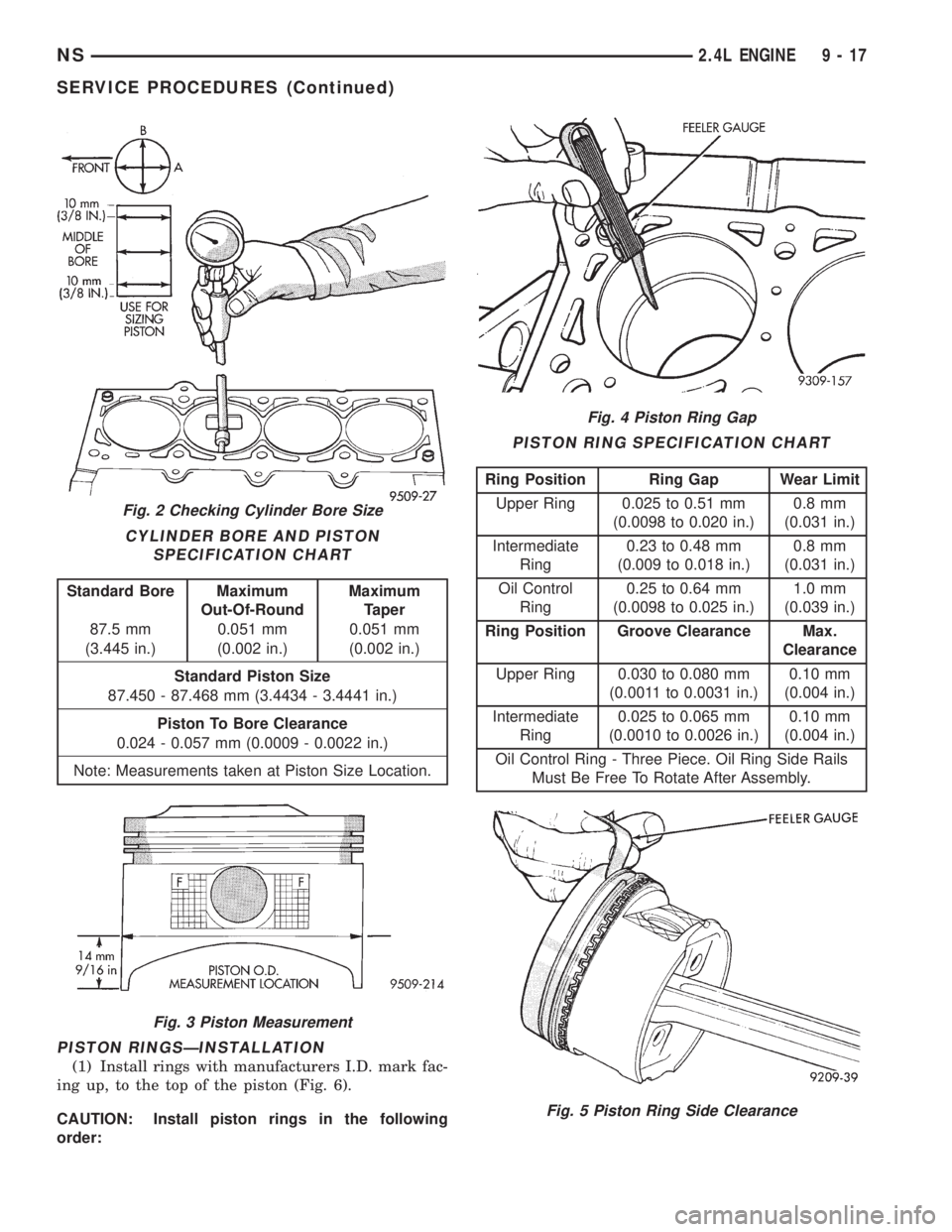
FITTING PISTONS
Piston and cylinder wall must be clean and dry.
Piston diameter should be measured 90 degrees to
piston pin about 14 mm (9/16 inch.) from the bottom
of the skirt as shown in (Fig. 3). Cylinder bores
should be measured halfway down the cylinder bore
and transverse to the engine crankshaft center line
shown in (Fig. 2). Refer to Cylinder Bore and Piston
Specification Chart.
Correct piston to bore clearance must be estab-
lished in order to assure quiet and economical oper-
ation.
Chrysler engines use pistons designed specifically
for each engine model. Clearance and sizing locations
vary with respect to engine model.
NOTE: Pistons and cylinder bores should be mea-
sured at normal room temperature, 70ÉF (21ÉC).
FITTING PISTON RINGS
(1) Wipe cylinder bore clean. Insert ring and push
down with piston to ensure it is square in bore. The
ring gap measurement must be made with the ring
positioning at least 12 mm (0.50 inch) from bottom of
cylinder bore. Check gap with feeler gauge (Fig. 4).
Refer to specification in Piston Ring Specification
Chart.
(2) Check piston ring to groove side clearance (Fig.
5). Refer to specification in Piston Ring Specification
Chart.
9 - 16 2.4L ENGINENS
DESCRIPTION AND OPERATION (Continued)
Page 1067 of 1938
PISTON RINGSÐINSTALLATION
(1) Install rings with manufacturers I.D. mark fac-
ing up, to the top of the piston (Fig. 6).
CAUTION: Install piston rings in the following
order:
Fig. 2 Checking Cylinder Bore Size
CYLINDER BORE AND PISTON
SPECIFICATION CHART
Standard Bore Maximum
Out-Of-RoundMaximum
Taper
87.5 mm 0.051 mm 0.051 mm
(3.445 in.) (0.002 in.) (0.002 in.)
Standard Piston Size
87.450 - 87.468 mm (3.4434 - 3.4441 in.)
Piston To Bore Clearance
0.024 - 0.057 mm (0.0009 - 0.0022 in.)
Note: Measurements taken at Piston Size Location.
Fig. 3 Piston Measurement
Fig. 4 Piston Ring Gap
PISTON RING SPECIFICATION CHART
Ring Position Ring Gap Wear Limit
Upper Ring 0.025 to 0.51 mm
(0.0098 to 0.020 in.)0.8 mm
(0.031 in.)
Intermediate
Ring0.23 to 0.48 mm
(0.009 to 0.018 in.)0.8 mm
(0.031 in.)
Oil Control
Ring0.25 to 0.64 mm
(0.0098 to 0.025 in.)1.0 mm
(0.039 in.)
Ring Position Groove Clearance Max.
Clearance
Upper Ring 0.030 to 0.080 mm
(0.0011 to 0.0031 in.)0.10 mm
(0.004 in.)
Intermediate
Ring0.025 to 0.065 mm
(0.0010 to 0.0026 in.)0.10 mm
(0.004 in.)
Oil Control Ring - Three Piece. Oil Ring Side Rails
Must Be Free To Rotate After Assembly.
Fig. 5 Piston Ring Side Clearance
NS2.4L ENGINE 9 - 17
SERVICE PROCEDURES (Continued)
Page 1069 of 1938
scale provided on the package. Locate the band clos-
est to the same width. This band shows the amount
of clearance in thousandths of a millimeter. Differ-
ences in readings between the ends indicate the
amount of taper present. Record all readings taken.
Refer to Engine Specifications.Plastigage gener-
ally is accompanied by two scales. One scale is
in inches, the other is a metric scale.
(6) Plastigage is available in a variety of clearance
ranges. The 0.025-0.076 mm (.001-.003 in.) is usually
the most appropriate for checking engine bearing
proper specifications.
FITTING MAIN BEARINGS
Refer to the Engine General Information Section
for Measuring Main Bearings. For Crankshaft speci-
fications refer to Crankshaft Specification Chart.
CRANKSHAFT MAIN BEARINGS
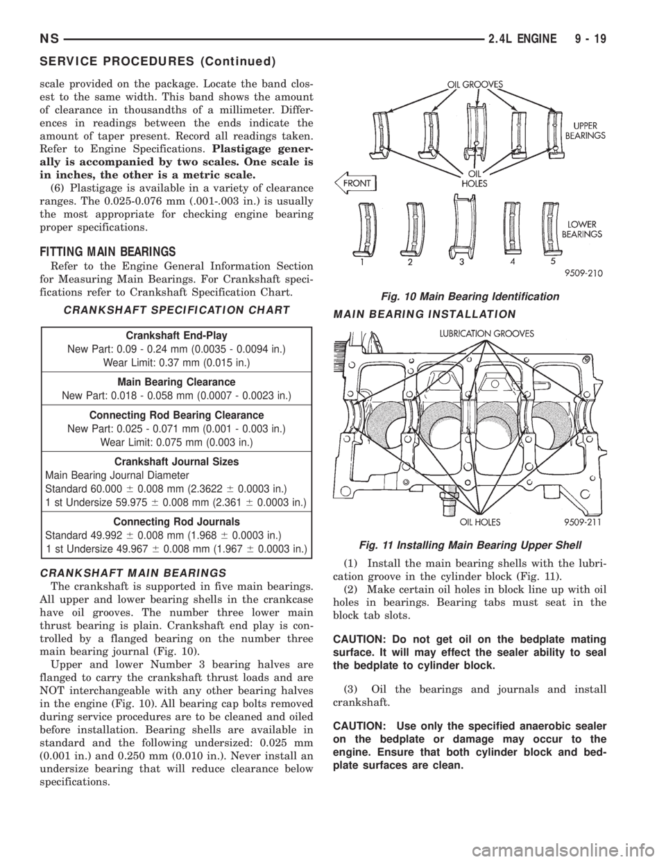
The crankshaft is supported in five main bearings.
All upper and lower bearing shells in the crankcase
have oil grooves. The number three lower main
thrust bearing is plain. Crankshaft end play is con-
trolled by a flanged bearing on the number three
main bearing journal (Fig. 10).
Upper and lower Number 3 bearing halves are
flanged to carry the crankshaft thrust loads and are
NOT interchangeable with any other bearing halves
in the engine (Fig. 10). All bearing cap bolts removed
during service procedures are to be cleaned and oiled
before installation. Bearing shells are available in
standard and the following undersized: 0.025 mm
(0.001 in.) and 0.250 mm (0.010 in.). Never install an
undersize bearing that will reduce clearance below
specifications.
MAIN BEARING INSTALLATION
(1) Install the main bearing shells with the lubri-
cation groove in the cylinder block (Fig. 11).
(2) Make certain oil holes in block line up with oil
holes in bearings. Bearing tabs must seat in the
block tab slots.
CAUTION: Do not get oil on the bedplate mating
surface. It will may effect the sealer ability to seal
the bedplate to cylinder block.
(3) Oil the bearings and journals and install
crankshaft.
CAUTION: Use only the specified anaerobic sealer
on the bedplate or damage may occur to the
engine. Ensure that both cylinder block and bed-
plate surfaces are clean.
CRANKSHAFT SPECIFICATION CHART
Crankshaft End-Play
New Part: 0.09 - 0.24 mm (0.0035 - 0.0094 in.)
Wear Limit: 0.37 mm (0.015 in.)
Main Bearing Clearance
New Part: 0.018 - 0.058 mm (0.0007 - 0.0023 in.)
Connecting Rod Bearing Clearance
New Part: 0.025 - 0.071 mm (0.001 - 0.003 in.)
Wear Limit: 0.075 mm (0.003 in.)
Crankshaft Journal Sizes
Main Bearing Journal Diameter
Standard 60.00060.008 mm (2.362260.0003 in.)
1 st Undersize 59.97560.008 mm (2.36160.0003 in.)
Connecting Rod Journals
Standard 49.99260.008 mm (1.96860.0003 in.)
1 st Undersize 49.96760.008 mm (1.96760.0003 in.)
Fig. 10 Main Bearing Identification
Fig. 11 Installing Main Bearing Upper Shell
NS2.4L ENGINE 9 - 19
SERVICE PROCEDURES (Continued)
Page 1070 of 1938
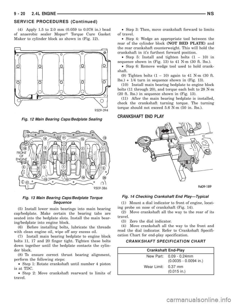
(4) Apply 1.5 to 2.0 mm (0.059 to 0.078 in.) bead
of anaerobic sealer MopartTorque Cure Gasket
Maker to cylinder block as shown in (Fig. 12).
(5) Install lower main bearings into main bearing
cap/bedplate. Make certain the bearing tabs are
seated into the bedplate slots. Install the main bear-
ing/bedplate into engine block.
(6) Before installing bolts, lubricate the threads
with clean engine oil, wipe off any excess oil.
(7) Install main bearing bedplate to engine block
bolts 11, 17 and 20 finger tight. Tighten these bolts
down together until the bedplate contacts the cylin-
der block.
(8) To ensure correct thrust bearing alignment,
perform the following steps:
²Step 1: Rotate crankshaft until number 4 piston
is at TDC.
²Step 2: Move crankshaft rearward to limits of
travel.²Step 3: Then, move crankshaft forward to limits
of travel.
²Step 4: Wedge an appropriate tool between the
rear of the cylinder block(NOT BED PLATE)and
the rear crankshaft counterweight. This will hold the
crankshaft in it's furthest forward position.
²Step 5: Install and tighten bolts (1 ± 10) in
sequence shown in (Fig. 13) to 41 N´m (30 ft. lbs.).
²Step 6: Remove wedge tool used to hold crank-
shaft.
(9) Tighten bolts (1 ± 10) again to 41 N´m (30 ft.
lbs.) + 1/4 turn in sequence shown in (Fig. 13).
(10) Install main bearing bedplate to engine block
bolts (11 through 20), and torque each bolt to 28 N´m
(20 ft. lbs.) in sequence shown in (Fig. 13).
(11) After the main bearing bedplate is installed,
check the crankshaft turning torque. The turning
torque should not exceed 5.6 N´m (50 in. lbs.).
CRANKSHAFT END PLAY
(1) Mount a dial indicator to front of engine, locat-
ing probe on nose of crankshaft (Fig. 14).
(2) Move crankshaft all the way to the rear of its
travel.
(3) Zero the dial indicator.
(4) Move crankshaft all the way to the front and
read the dial indicator. Refer to Crankshaft Specifi-
cation Chart for end-play specification.
Fig. 12 Main Bearing Caps/Bedplate Sealing
Fig. 13 Main Bearing Caps/Bedplate Torque
SequenceFig. 14 Checking Crankshaft End PlayÐTypical
CRANKSHAFT SPECIFICATION CHART
Crankshaft End-Play
New Part: 0.09 - 0.24mm
(0.0035 - 0.0094 in.)
Wear Limit: 0.37 mm
(0.015 in.)
9 - 20 2.4L ENGINENS
SERVICE PROCEDURES (Continued)
Page 1073 of 1938
need to be reground to prevent seal damage when
the valve is installed.
VALVE INSTALLATION
(1) Coat valve stems with clean engine oil and
insert in cylinder head.
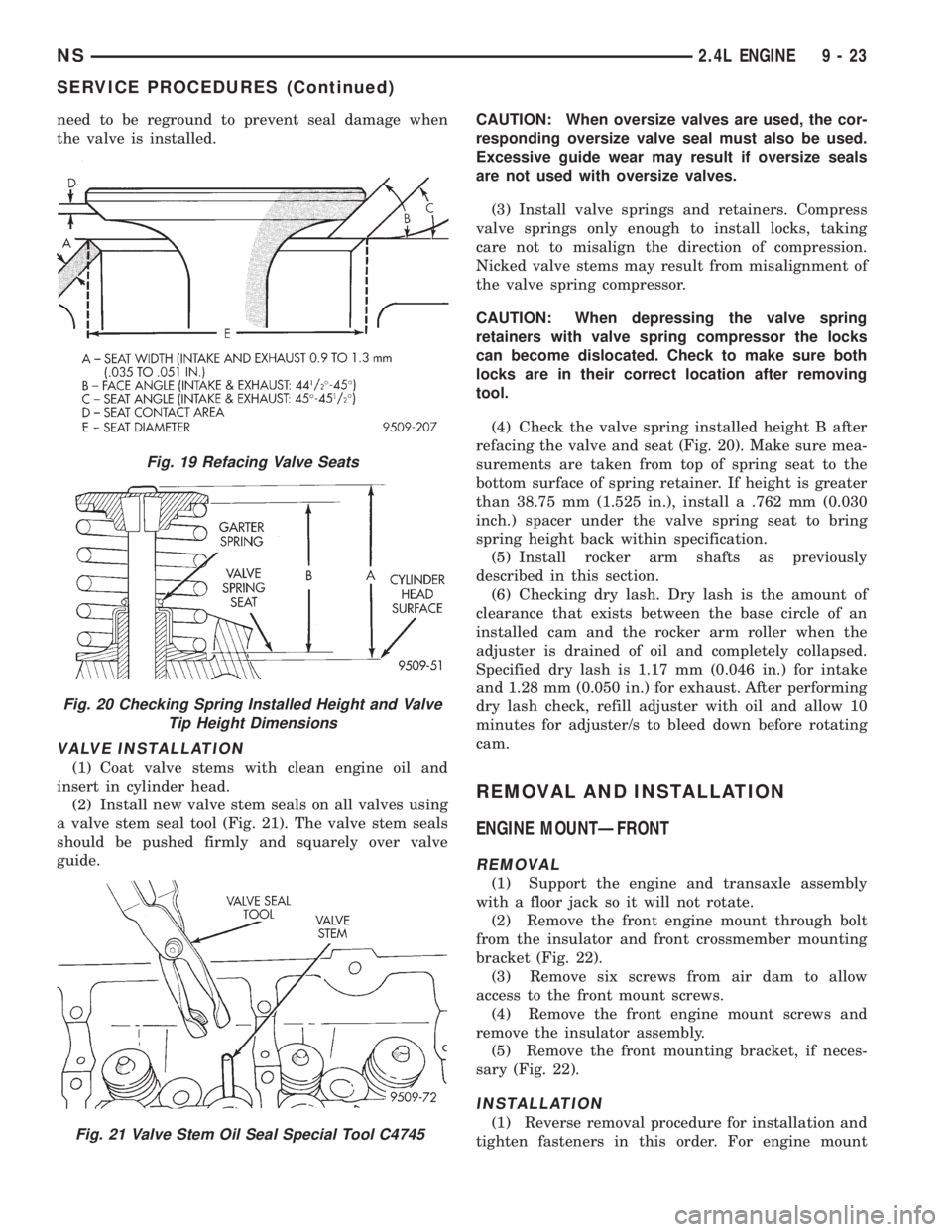
(2) Install new valve stem seals on all valves using
a valve stem seal tool (Fig. 21). The valve stem seals
should be pushed firmly and squarely over valve
guide.CAUTION: When oversize valves are used, the cor-
responding oversize valve seal must also be used.
Excessive guide wear may result if oversize seals
are not used with oversize valves.
(3) Install valve springs and retainers. Compress
valve springs only enough to install locks, taking
care not to misalign the direction of compression.
Nicked valve stems may result from misalignment of
the valve spring compressor.
CAUTION: When depressing the valve spring
retainers with valve spring compressor the locks
can become dislocated. Check to make sure both
locks are in their correct location after removing
tool.
(4) Check the valve spring installed height B after
refacing the valve and seat (Fig. 20). Make sure mea-
surements are taken from top of spring seat to the
bottom surface of spring retainer. If height is greater
than 38.75 mm (1.525 in.), install a .762 mm (0.030
inch.) spacer under the valve spring seat to bring
spring height back within specification.
(5) Install rocker arm shafts as previously
described in this section.
(6) Checking dry lash. Dry lash is the amount of
clearance that exists between the base circle of an
installed cam and the rocker arm roller when the
adjuster is drained of oil and completely collapsed.
Specified dry lash is 1.17 mm (0.046 in.) for intake
and 1.28 mm (0.050 in.) for exhaust. After performing
dry lash check, refill adjuster with oil and allow 10
minutes for adjuster/s to bleed down before rotating
cam.
REMOVAL AND INSTALLATION
ENGINE MOUNTÐFRONT
REMOVAL
(1) Support the engine and transaxle assembly
with a floor jack so it will not rotate.
(2) Remove the front engine mount through bolt
from the insulator and front crossmember mounting
bracket (Fig. 22).
(3) Remove six screws from air dam to allow
access to the front mount screws.
(4) Remove the front engine mount screws and
remove the insulator assembly.
(5) Remove the front mounting bracket, if neces-
sary (Fig. 22).
INSTALLATION
(1) Reverse removal procedure for installation and
tighten fasteners in this order. For engine mount
Fig. 19 Refacing Valve Seats
Fig. 20 Checking Spring Installed Height and Valve
Tip Height Dimensions
Fig. 21 Valve Stem Oil Seal Special Tool C4745
NS2.4L ENGINE 9 - 23
SERVICE PROCEDURES (Continued)
Page 1084 of 1938
CYLINDER HEAD
REMOVAL
(1) Perform fuel system pressure release proce-
durebefore attempting any repairs.Refer to
Group 14, Fuel System for procedure.
(2) Disconnect negative battery cable. Drain cool-
ing system. Refer to Group 7, Cooling System for pro-
cedure.
(3) Remove air cleaner and disconnect all vacuum
lines, electrical wiring and fuel lines from throttle
body.
(4) Remove throttle linkage. Refer to Group 14,
Fuel System for procedures
(5) Remove accessory drive belts. Refer to Group
7, Cooling System for procedure.
(6) Remove power brake vacuum hose from intake
manifold.
(7) Raise vehicle and remove exhaust pipe from
manifold.(8) Remove power steering pump assembly and
set aside.
(9) Disconnect coil pack wiring connector and
remove coil pack and plug wires from engine.
(10) Remove cam sensor and fuel injectors wiring
connectors.
(11) Remove timing belt and camshaft sprocket.
Refer to procedure outlined in this section.
(12) Remove timing belt idler pulley and rear tim-
ing belt cover.
(13) Remove cylinder head cover using procedure
outlined in this section.
(14) Remove camshafts and cam followers. Refer to
procedures outlined in this section for procedures.
(15) Remove cylinder head bolts and remove cyl-
inder head from engine block.
(16) Inspect and clean cylinder head. Refer to
Cleaning and Inspection outlined in this section for
procedures.
INSTALLATION
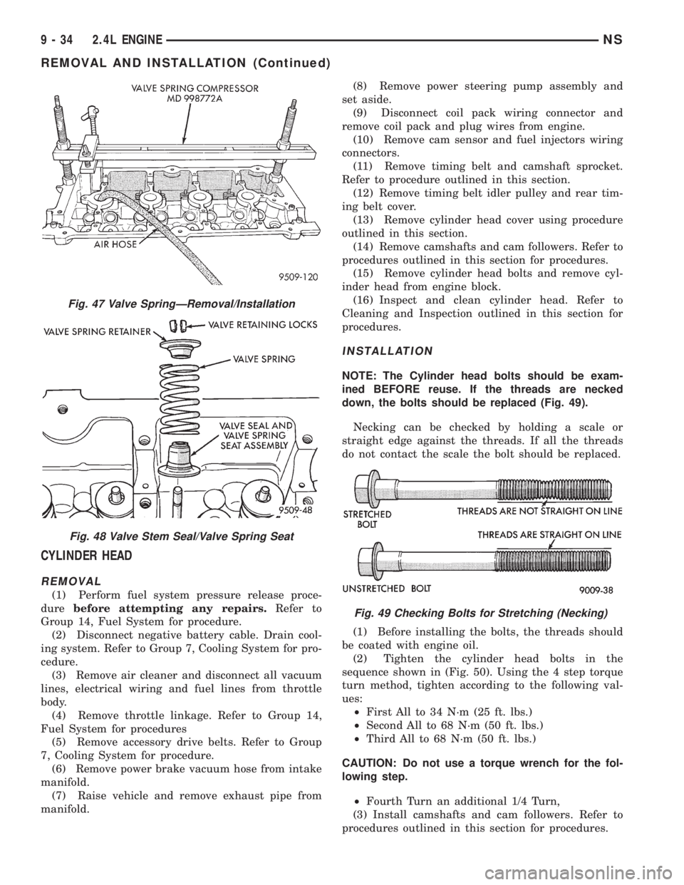
NOTE: The Cylinder head bolts should be exam-
ined BEFORE reuse. If the threads are necked
down, the bolts should be replaced (Fig. 49).
Necking can be checked by holding a scale or
straight edge against the threads. If all the threads
do not contact the scale the bolt should be replaced.
(1) Before installing the bolts, the threads should
be coated with engine oil.
(2) Tighten the cylinder head bolts in the
sequence shown in (Fig. 50). Using the 4 step torque
turn method, tighten according to the following val-
ues:
²First All to 34 N´m (25 ft. lbs.)
²Second All to 68 N´m (50 ft. lbs.)
²Third All to 68 N´m (50 ft. lbs.)
CAUTION: Do not use a torque wrench for the fol-
lowing step.
²Fourth Turn an additional 1/4 Turn,
(3) Install camshafts and cam followers. Refer to
procedures outlined in this section for procedures.
Fig. 47 Valve SpringÐRemoval/Installation
Fig. 48 Valve Stem Seal/Valve Spring Seat
Fig. 49 Checking Bolts for Stretching (Necking)
9 - 34 2.4L ENGINENS
REMOVAL AND INSTALLATION (Continued)