1996 CHRYSLER VOYAGER transmission fluid
[x] Cancel search: transmission fluidPage 1545 of 1938

41TE AUTOMATIC TRANSAXLE
INDEX
page page
GENERAL INFORMATION
41TE FOUR SPEED AUTOMATIC TRANSAXLE . 71
FLUID LEVEL AND CONDITION............. 72
SELECTION OF LUBRICANT............... 72
SPECIAL ADDITIVES..................... 72
DESCRIPTION AND OPERATION
ADAPTIVE CONTROLS................... 73
CLUTCH AND GEAR..................... 72
ELECTRONICS......................... 73
GEARSHIFT AND PARKING LOCK CONTROLS . 74
HYDRAULICS........................... 73
ON-BOARD DIAGNOSTICS................ 74
SENSORS............................. 73
SHIFT POSITION INDICATOR.............. 74
SOLENOIDS............................ 73
TORQUE MANAGEMENT.................. 74
TRANSMISSION CONTROL MODULE........ 74
TRANSMISSION RANGE SENSOR........... 74
DIAGNOSIS AND TESTING
41TE TRANSAXLE GENERAL DIAGNOSIS..... 75
CLUTCH AIR PRESSURE TESTS............ 77
FLUID LEAKAGE-TORQUE CONVERTER
HOUSING AREA....................... 78
HYDRAULIC PRESSURE TESTS............ 75
ROAD TEST............................ 75
SHIFT POSITION INDICATOR.............. 78
SERVICE PROCEDURES
ALUMINUM THREAD REPAIR.............. 81
FLUID AND FILTER CHANGE............... 79
FLUID DRAIN AND REFILL................. 81
FLUSHING COOLERS AND TUBES.......... 81OIL PUMP VOLUME CHECK............... 82
PINION FACTOR PROCEDURE............. 83
TRANSAXLE QUICK LEARN PROCEDURE.... 82
REMOVAL AND INSTALLATION
GEARSHIFT CABLE...................... 83
MANUAL VALVE LEVER (SHIFT LEVER)...... 84
OIL PUMP SEAL......................... 92
SOLENOID ASSEMBLY-REPLACE........... 85
SPEED SENSOR-INPUT................... 86
SPEED SENSOR-OUTPUT................. 86
TRANSAXLE........................... 89
TRANSMISSION CONTROL MODULE........ 87
TRANSMISSION RANGE SENSOR........... 85
VALVE BODY........................... 88
DISASSEMBLY AND ASSEMBLY
DIFFERENTIAL REPAIR.................. 139
INPUT CLUTCHES-RECONDITION.......... 110
TRANSAXLE ASSEMBLE................. 122
TRANSAXLE DISASSEMBLE............... 95
VALVE BODY RECONDITION............... 92
CLEANING AND INSPECTION
CLEANING VALVE BODY................. 144
ADJUSTMENTS
GEARSHIFT CABLE ADJUSTMENT......... 144
SCHEMATICS AND DIAGRAMS
41TE TRANSAXLE HYDRAULIC SCHEMATICS . 145
SPECIFICATIONS
41TE AUTOMATIC TRANSAXLE............ 158
41TE TORQUE SPECIFICATIONS.......... 158
SPECIAL TOOLS
41TE AUTOMATIC TRANSAXLE............ 159
GENERAL INFORMATION
41TE FOUR SPEED AUTOMATIC TRANSAXLE
The 41TE four-speed FWD transaxle uses fully-
adaptive controls. Adaptive controls are those which
perform their functions based on real-time feedback
sensor information. The transaxle uses hydraulically
applied clutches to shift a planetary gear train.
TRANSAXLE IDENTIFICATION
The 41TE transaxle identification code is printed
on a label. The label is located on the transaxle case
next to the solenoid assembly (Fig. 1).
Fig. 1 Identification Tag Location
NSTRANSAXLE AND POWER TRANSFER UNIT 21 - 71
Page 1546 of 1938
OPERATION
The gear ratios for the 41TE transaxle are as fol-
lows:
²1stÐ2.84
²2ndÐ1.57
²3rdÐ1.00
²ODÐ0.69
²ReverseÐ2.21
Final Drive Ratio is dependent on which engine
option is selected.
²2.4 Liter: 3.91 FDR
²3.3 Liter: 3.62 FDR
²3.8 Liter: 3.45 FDR
The torque converter clutch is available in 2nd,
direct, or overdrive gear;. The shift lever is conven-
tional with six positions: P, R, N, OD, 3, and L avail-
able. When OD is selected the transaxle shifts
through all four speeds with torque converter clutch
available in overdrive. This position is recommended
for most driving. The 3 position is tailored for use in
hilly or mountainous driving. When 3 is selected, the
transmission uses only 1st, 2nd, and direct gears
with 2nd-direct shift delayed to 40 mph or greater.
When operating in 3 or L positions torque converter
clutch application occurs in direct gear. This
improves transmission cooling under heavy loads. If
high engine coolant temperature occurs, the torque
converter clutch will also engage in 2nd gear. The L
position provides maximum engine braking for
descending steep grades. Unlike most current tran-
saxles, upshifts are provided to 2nd or direct gear at
peak engine speeds if the accelerator is depressed.
This provides engine over-speed protection and max-
imum performance.
FLUID LEVEL AND CONDITION
NOTE: The transmission and differential sump have
a common oil sump with an opening between the
two.
The torque converter fills in both the (P) Park and
(N) Neutral positions. Place the selector lever in (P)
Park to check the fluid level.The engine should be
running at idle speed for at least one minute,
with the vehicle on level ground. This will
assure complete oil level stabilization between
differential and transmission.The fluid should be
at normal operating temperature (approximately 82
C. or 180 F.). The fluid level is correct if it is in the
HOTregion (cross-hatched area) on the oil level indi-
cator.
Low fluid level can cause a variety of conditions
because it allows the pump to take in air along with
the fluid. As in any hydraulic system, air bubbles
make the fluid spongy, therefore, pressures will be
low and build up slowly.Improper filling can also raise the fluid level too
high. When the transaxle has too much fluid, the
gears churn up foam and cause the same conditions
which occur with a low fluid level.
In either case, the air bubbles can cause overheat-
ing, fluid oxidation, and varnishing. This can inter-
fere with normal valve, clutch, and accumulator
operation. Foaming can also result in fluid escaping
from the transaxle vent where it may be mistaken
for a leak.
Along with fluid level, it is important to check the
condition of the fluid. When the fluid smells burned,
and is contaminated with metal or friction material
particles, a complete transaxle overhaul is needed.
Be sure to examine the fluid on the dipstick closely.
If there is any doubt about its condition, drain out a
sample for a double check.
After the fluid has been checked, seat the dipstick
fully to seal out water and dirt.
SELECTION OF LUBRICANT
It is important that the proper lubricant be used in
the 41TE transaxle. MOPARtATF PLUS 3 (Auto-
matic Transmission FluidÐtype 7176) should be used
to aid in assuring optimum transmission perfor-
mance. Fluids of the type labeled DEXRON II Auto-
matic Transmission Fluid arenot recommended.It
is important that the transmission fluid be main-
tained at the prescribed level using the recommended
fluids.
SPECIAL ADDITIVES
Chrysler Corporation does not recommend the
addition of any fluids to the transaxle, other than the
fluid listed above. An exception to this policy is the
use of special dyes to aid in detecting fluid leaks. The
use of transmission sealers should be avoided, since
they may adversely affect seals.
DESCRIPTION AND OPERATION
CLUTCH AND GEAR
The transaxle consists of:
²Three multiple disc input clutches
²Two multiple disc grounded clutches
²Four hydraulic accumulators
²Two planetary gear sets
This provides four forward ratios and a reverse
ratio. The input clutch-apply pistons were designed
with centrifugally balanced oil cavities so that quick
response and good control can be achieved at any
speed. A push/pull piston is incorporated for two of
the three input clutches.
21 - 72 TRANSAXLE AND POWER TRANSFER UNITNS
GENERAL INFORMATION (Continued)
Page 1548 of 1938
TORQUE MANAGEMENT
Most 41TE transaxles utilize torque management.
Torque management is a unique function of the Pow-
ertrain Control Module (PCM). The PCM receives
output signals from the Transmission Control Module
(TCM) and many various engine sensors. The PCM
evaluates these signals and decides if it is necessary
to decrease the output of the engine's torque. This
reduction in torque does not interfere with the nor-
mal operation of the vehicle. This reduction in torque
will prolong the life of the drivetrain components.
Torque reduction is not noticeable in normal driving
functions. The torque reduction function shuts off
above 16 MPH.
ON-BOARD DIAGNOSTICS
This vehicle utilizes a diagnostic system called
OBDII. The powertrain control module communicates
with the Transmission Control Module. Whenever
the transaxle sets a fault in the Transmission Con-
trol Module (dependent on which fault is set), the
powertrain control module will turn on a MIL (Mal-
function Indicator Lamp) on the instrument cluster.
By reading the code in the powertrain control module
it will tell you where the fault occurred. If the fault
occurred in the transaxle, the controller will read a
CODE 45.For further information regarding OBDII,
refer to Group 25, Emission Systems.
These controls provide comprehensive, on-board
transaxle diagnostics. The information available can
aid in transaxle diagnosis. For example, apply ele-
ment buildup rate indicates solenoid performance.
Also included are self diagnostic functions. Self diag-
nostics allow the technician to test the condition of
the electronic controls. The Transmission Control
Module continuously monitors its critical functions. It
also records any malfunctions, and the number of
engine starts since the last malfunction. This allows
the technician to use the information in the event of
a customer complaint.
TRANSMISSION CONTROL MODULE
Do not interchange Transmission Control Modules
with previous year transmission control modules. If a
same year TCM is being used from a different vehi-
cle, the following procedures must be performed:
²Quick Learn Procedure
²Electronic Pinion Factor Procedure
The Transmission Control Module is located on the
right inner fender panel, in the engine compartment.
It is held in place by four mounting screws.NOTE: If the Transmission Control Module has
been replaced, the following procedures must be
performed:
²Quick Learn Procedure: This procedure will
allow the transmission control module to learn the
characteristics of the vehicle.
²Electronic Pinion Factor Procedure: This proce-
dure will reprogram the TCM to compensate for dif-
ferent tire sizes and final drive ratios.
GEARSHIFT AND PARKING LOCK CONTROLS
The transaxle is controlled by a lever type gear-
shift incorporated within the steering column. The
control has six selector lever positions: P (park), R
(reverse), N (neutral), and D (drive), 2 (second), and
1 (first). The parking lock is applied by moving the
selector lever past a gate to the P position.Do not
apply the parking lock until the vehicle has
stopped; otherwise, a severe ratchet noise will
occur.
TRANSMISSION RANGE SENSOR
The 41TE transaxle is equipped with a transmis-
sion range sensor that is located on top of the valve
body. This sensor will allow for accurate transmission
gear position measurement.
To service the transmission range sensor (TRS),
you must remove the valve body. For repair proce-
dures, refer to the Removal and Installation section
within this group.
Also located within the TRS is a transmission tem-
perature sensor. This sensor is used to measure the
transmission fluid sump temperature. The transmis-
sion temperature sensor is serviced with the TRS as
a unit.
SHIFT POSITION INDICATOR
The shifter position indicator is located in the
instrument cluster. The shifter position indicator out-
lines with a box the gear position the transaxle man-
ual valve lever is in.
The transmission range sensor (located on the
valvebody) sends a signal to the TCM on the position
of the transaxle manual valve lever. The TCM
receives the switch signal and processes the data.
The TCM sends the Shift Lever Position (SLP) infor-
mation to the BCM via the CCD bus. The BCM then
outlines with a box the appropriate shifter position
indicator in the instrument cluster.
To replace the shifter position indicator, refer to
Group 8E, Instrument Panel And Gauges.
21 - 74 TRANSAXLE AND POWER TRANSFER UNITNS
DESCRIPTION AND OPERATION (Continued)
Page 1552 of 1938
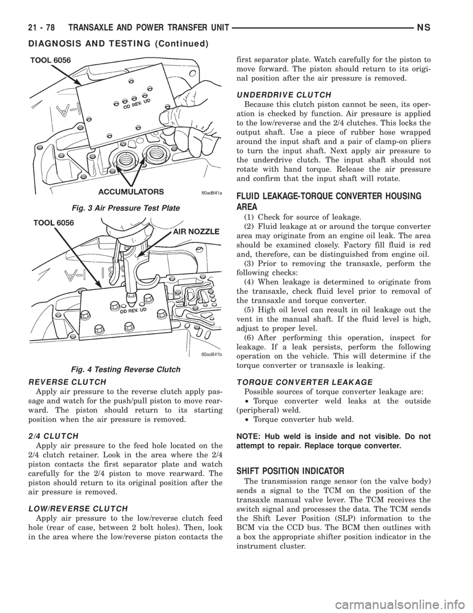
REVERSE CLUTCH
Apply air pressure to the reverse clutch apply pas-
sage and watch for the push/pull piston to move rear-
ward. The piston should return to its starting
position when the air pressure is removed.
2/4 CLUTCH
Apply air pressure to the feed hole located on the
2/4 clutch retainer. Look in the area where the 2/4
piston contacts the first separator plate and watch
carefully for the 2/4 piston to move rearward. The
piston should return to its original position after the
air pressure is removed.
LOW/REVERSE CLUTCH
Apply air pressure to the low/reverse clutch feed
hole (rear of case, between 2 bolt holes). Then, look
in the area where the low/reverse piston contacts thefirst separator plate. Watch carefully for the piston to
move forward. The piston should return to its origi-
nal position after the air pressure is removed.
UNDERDRIVE CLUTCH
Because this clutch piston cannot be seen, its oper-
ation is checked by function. Air pressure is applied
to the low/reverse and the 2/4 clutches. This locks the
output shaft. Use a piece of rubber hose wrapped
around the input shaft and a pair of clamp-on pliers
to turn the input shaft. Next apply air pressure to
the underdrive clutch. The input shaft should not
rotate with hand torque. Release the air pressure
and confirm that the input shaft will rotate.
FLUID LEAKAGE-TORQUE CONVERTER HOUSING
AREA
(1) Check for source of leakage.
(2) Fluid leakage at or around the torque converter
area may originate from an engine oil leak. The area
should be examined closely. Factory fill fluid is red
and, therefore, can be distinguished from engine oil.
(3) Prior to removing the transaxle, perform the
following checks:
(4) When leakage is determined to originate from
the transaxle, check fluid level prior to removal of
the transaxle and torque converter.
(5) High oil level can result in oil leakage out the
vent in the manual shaft. If the fluid level is high,
adjust to proper level.
(6) After performing this operation, inspect for
leakage. If a leak persists, perform the following
operation on the vehicle. This will determine if the
torque converter or transaxle is leaking.
TORQUE CONVERTER LEAKAGE
Possible sources of torque converter leakage are:
²Torque converter weld leaks at the outside
(peripheral) weld.
²Torque converter hub weld.
NOTE: Hub weld is inside and not visible. Do not
attempt to repair. Replace torque converter.
SHIFT POSITION INDICATOR
The transmission range sensor (on the valve body)
sends a signal to the TCM on the position of the
transaxle manual valve lever. The TCM receives the
switch signal and processes the data. The TCM sends
the Shift Lever Position (SLP) information to the
BCM via the CCD bus. The BCM then outlines with
a box the appropriate shifter position indicator in the
instrument cluster.
Fig. 3 Air Pressure Test Plate
Fig. 4 Testing Reverse Clutch
21 - 78 TRANSAXLE AND POWER TRANSFER UNITNS
DIAGNOSIS AND TESTING (Continued)
Page 1555 of 1938
(11) Recheck the fluid level after the transaxle is
at normal operating temperature. The level should be
in the HOT range. Drive the vehicle a minimum of
10 miles.
(12) Raise the vehicle on the hoist.
(13) Remove the pan and clean all sealant from
the pan and transaxle mating surfaces. Clean the
magnet and the inside of the pan.
(14) Separate the filter from the valve body to
allow additional fluid to drain from the transaxle.
Inspect the filter O-ring for any damage and replace
as necessary.
(15) After the transaxle has stopped draining,
reinstall the filter and O-ring.
(16) Apply a 1/8 inch bead of Mopar RTV Sealant
to the mounting flange of the transaxle oil pan.
Apply RTV Sealant to the underside of the attaching
bolts. Attach the oil pan to the transaxle. Tighten the
bolts to 19 N´m (165 in. lbs.).
(17) Lower the vehicle and add 4 Quarts of Mopar
ATF Plus 3 Type 7176 transaxle fluid.
(18) Start the engine and allow it to idle for a min-
imum of one minute. With the parking brake applied,
press your foot on the service brake and cycle the
transaxle from park to all gear positions ending in
neutral or park.
(19) Check the transaxle fluid level and add an
appropriate amount to bring the transaxle fluid level
to 3mm (1/8 in.) below the ADD mark on the dip-
stick.
(20) Recheck the fluid level after the transaxle is
at normal operating temperature. The level should be
in the HOT range.
FLUID DRAIN AND REFILL
(1) Raise vehicle on a hoist (See Group 0, Lubrica-
tion). Place a drain container with a large opening,
under transaxle oil pan.
(2) Loosen pan bolts and tap the pan at one corner
to break it loose allowing fluid to drain, then remove
the oil pan.
(3) Install a new filter and O-ring on bottom of the
valve body.
(4) Clean the oil pan and magnet. Reinstall pan
using new MOPARtRTV sealant. Tighten oil pan
bolts to 19 N´m (165 in. lbs.).
(5) Pour four quarts of MOPARtATF PLUS 3
(Automatic Transmission Fluid) Type 7176 through
the fill tube.
(6) Start engine and allow to idle for at least one
minute. Then, with parking and service brakes
applied, move selector lever momentarily to each
position, ending in the park or neutral position.(7) Add sufficient fluid to bring level to 1/8 inch
below the ADD mark.
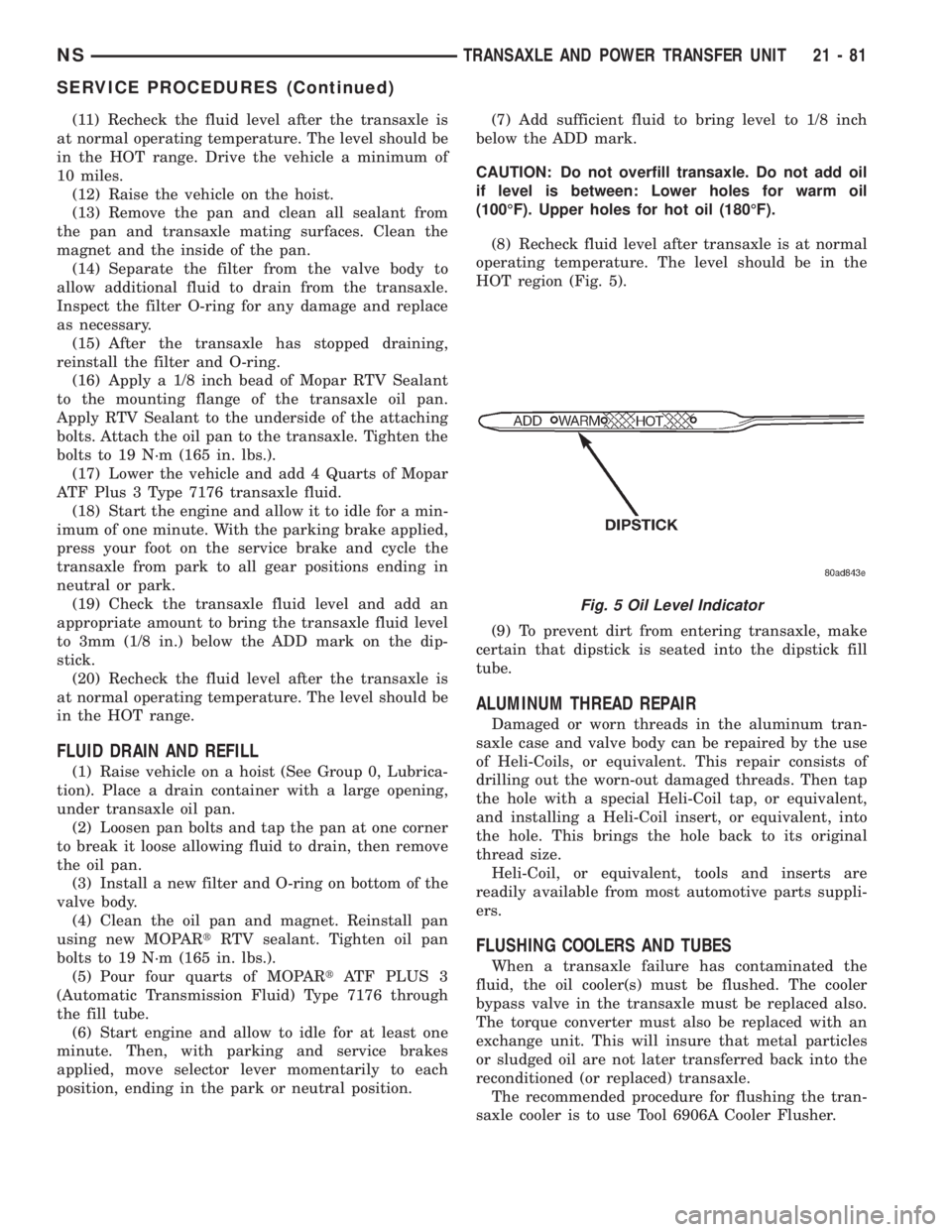
CAUTION: Do not overfill transaxle. Do not add oil
if level is between: Lower holes for warm oil
(100ÉF). Upper holes for hot oil (180ÉF).
(8) Recheck fluid level after transaxle is at normal
operating temperature. The level should be in the
HOT region (Fig. 5).
(9) To prevent dirt from entering transaxle, make
certain that dipstick is seated into the dipstick fill
tube.
ALUMINUM THREAD REPAIR
Damaged or worn threads in the aluminum tran-
saxle case and valve body can be repaired by the use
of Heli-Coils, or equivalent. This repair consists of
drilling out the worn-out damaged threads. Then tap
the hole with a special Heli-Coil tap, or equivalent,
and installing a Heli-Coil insert, or equivalent, into
the hole. This brings the hole back to its original
thread size.
Heli-Coil, or equivalent, tools and inserts are
readily available from most automotive parts suppli-
ers.
FLUSHING COOLERS AND TUBES
When a transaxle failure has contaminated the
fluid, the oil cooler(s) must be flushed. The cooler
bypass valve in the transaxle must be replaced also.
The torque converter must also be replaced with an
exchange unit. This will insure that metal particles
or sludged oil are not later transferred back into the
reconditioned (or replaced) transaxle.
The recommended procedure for flushing the tran-
saxle cooler is to use Tool 6906A Cooler Flusher.
Fig. 5 Oil Level Indicator
NSTRANSAXLE AND POWER TRANSFER UNIT 21 - 81
SERVICE PROCEDURES (Continued)
Page 1556 of 1938
WARNING: WEAR PROTECTIVE EYEWEAR THAT
MEETS THE REQUIREMENTS OF OSHA AND ANSI
Z87.1±1968. WEAR STANDARD INDUSTRIAL RUB-
BER GLOVES.
KEEP LIGHTED CIGARETTES, SPARKS, FLAMES,
AND OTHER IGNITION SOURCES AWAY FROM THE
AREA TO PREVENT THE IGNITION OF COMBUSTI-
BLE LIQUIDS AND GASES. KEEP A CLASS (B) FIRE
EXTINGUISHER IN THE AREA WHERE THE
FLUSHER WILL BE USED.
KEEP THE AREA WELL VENTILATED.
DO NOT LET FLUSHING SOLVENT COME IN CON-
TACT WITH YOUR EYES OR SKIN: IF EYE CONTAM-
INATION OCCURS, FLUSH EYES WITH WATER FOR
15 TO 20 SECONDS. REMOVE CONTAMINATED
CLOTHING AND WASH AFFECTED SKIN WITH
SOAP AND WATER. SEEK MEDICAL ATTENTION.
COOLER FLUSH USING TOOL 6906A
(1) Remove cover plate filler plug on Tool 6906A.
Fill reservoir 1/2 to 3/4 full of fresh flushing solution.
Flushing solvents are petroleum based solutions gen-
erally used to clean automatic transmission compo-
nents.DO NOTuse solvents containing acids, water,
gasoline, or any other corrosive liquids.
(2) Reinstall filler plug on Tool 6906A.
(3) Verify pump power switch is turned OFF. Con-
nect red alligator clip to positive (+) battery post.
Connect black (-) alligator clip to a good ground.
(4) Disconnect the cooler lines at the transmission.
NOTE: When flushing transmission cooler and
lines, ALWAYS reverse flush.
(5) Connect the BLUE pressure line to the OUT-
LET (From) cooler line.
(6) Connect the CLEAR return line to the INLET
(To) cooler line
(7) Turn pump ON for two to three minutes to
flush cooler(s) and lines. Monitor pressure readings
and clear return lines. Pressure readings should sta-
bilize below 20 psi. for vehicles equipped with a sin-
gle cooler and 30 psi. for vehicles equipped with dual
coolers. If flow is intermittent or exceeds these pres-
sures, replace cooler.
(8) Turn pump OFF.
(9) Disconnect CLEAR suction line from reservoir
at cover plate. Disconnect CLEAR return line at
cover plate, and place it in a drain pan.
(10) Turn pump ON for 30 seconds to purge flush-
ing solution from cooler and lines. Turn pump OFF.
(11) Place CLEAR suction line into a one quart
container of MopartATF PLUS 3 Type 7176 auto-
matic transmission fluid.
(12) Turn pump ON until all transmission fluid is
removed from the one quart container and lines. Thispurges any residual cleaning solvent from the trans-
mission cooler and lines. Turn pump OFF.
(13) Disconnect alligator clips from battery. Recon-
nect flusher lines to cover plate, and remove flushing
adapters from cooler lines.
OIL PUMP VOLUME CHECK
After the new or repaired transmission has been
installed, fill to the proper level with Mopar ATF
PLUS 3 (Type 7176) automatic transmission fluid.
The volume should be checked using the following
procedure:
(1) Disconnect theFrom coolerline at the trans-
mission and place a collecting container under the
disconnected line.
CAUTION: With the fluid set at the proper level,
fluid collection should not exceed (1) quart or inter-
nal damage to the transmission may occur.
(2) Run the engineat curb idle speed, with the
shift selector in neutral.
(3) If fluid flow is intermittent or it takes more
than 20 seconds to collect one quart of ATF, discon-
nect theTo Coolerline at the transaxle.
(4) Refill the transaxle to proper level and recheck
pump volume.
(5) If flow is found to be within acceptable limits,
replace the cooler. Then fill transmission to the
proper level, using Mopar ATF PLUS 3 (Type 7176)
automatic transmission fluid.
(6) If fluid flow is still found to be inadequate,
check the line pressure using the Transaxle Hydrau-
lic Pressure Test procedure.
(7) Check the cooler for debris on the external sur-
faces. Clean as necessary.
TRANSAXLE QUICK LEARN PROCEDURE
The quick learn procedure requires the use of the
DRBIII scan tool.
This program allows the electronic transaxle sys-
tem to recalibrate itself. This will provide the best
possible transaxle operation. The quick learn proce-
dure should be performed if any of the following pro-
cedures are performed:
²Transaxle Assembly Replacement
²Transmission Control Module Replacement
²Solenoid Pack Replacement
²Clutch Plate and/or Seal Replacement
²Valve Body Replacement or Recondition
To perform the Quick Learn Procedure, the follow-
ing conditions must be met:
²The brakes must be applied
²The engine speed must be above 500 rpm
²The throttle angle (TPS) must be less than 3
degrees
21 - 82 TRANSAXLE AND POWER TRANSFER UNITNS
SERVICE PROCEDURES (Continued)
Page 1559 of 1938
SOLENOID ASSEMBLY-REPLACE
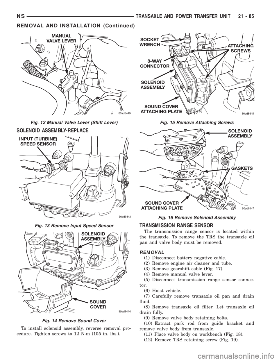
To install solenoid assembly, reverse removal pro-
cedure. Tighten screws to 12 N´m (105 in. lbs.).
TRANSMISSION RANGE SENSOR
The transmission range sensor is located within
the transaxle. To remove the TRS the transaxle oil
pan and valve body must be removed.
REMOVAL
(1) Disconnect battery negative cable.
(2) Remove engine air cleaner and tube.
(3) Remove gearshift cable (Fig. 17).
(4) Remove manual valve lever.
(5) Disconnect transmission range sensor connec-
tor.
(6) Hoist vehicle.
(7) Carefully remove transaxle oil pan and drain
fluid.
(8) Remove transaxle oil filter. Let transaxle oil
drain fully.
(9) Remove valve body retaining bolts.
(10) Extract park rod from guide bracket and
remove valve body from transaxle.
(11) Place valve body on workbench (Fig. 18).
(12) Remove TRS retaining screw (Fig. 19).
Fig. 12 Manual Valve Lever (Shift Lever)
Fig. 13 Remove Input Speed Sensor
Fig. 14 Remove Sound Cover
Fig. 15 Remove Attaching Screws
Fig. 16 Remove Solenoid Assembly
NSTRANSAXLE AND POWER TRANSFER UNIT 21 - 85
REMOVAL AND INSTALLATION (Continued)
Page 1565 of 1938
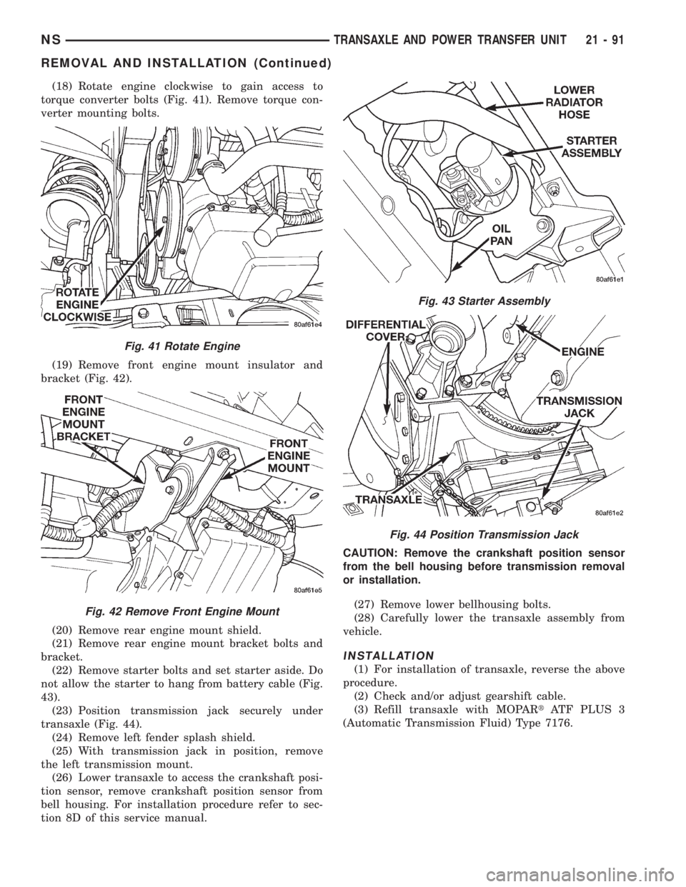
(18) Rotate engine clockwise to gain access to
torque converter bolts (Fig. 41). Remove torque con-
verter mounting bolts.
(19) Remove front engine mount insulator and
bracket (Fig. 42).
(20) Remove rear engine mount shield.
(21) Remove rear engine mount bracket bolts and
bracket.
(22) Remove starter bolts and set starter aside. Do
not allow the starter to hang from battery cable (Fig.
43).
(23) Position transmission jack securely under
transaxle (Fig. 44).
(24) Remove left fender splash shield.
(25) With transmission jack in position, remove
the left transmission mount.
(26) Lower transaxle to access the crankshaft posi-
tion sensor, remove crankshaft position sensor from
bell housing. For installation procedure refer to sec-
tion 8D of this service manual.CAUTION: Remove the crankshaft position sensor
from the bell housing before transmission removal
or installation.
(27) Remove lower bellhousing bolts.
(28) Carefully lower the transaxle assembly from
vehicle.
INSTALLATION
(1) For installation of transaxle, reverse the above
procedure.
(2) Check and/or adjust gearshift cable.
(3) Refill transaxle with MOPARtATF PLUS 3
(Automatic Transmission Fluid) Type 7176.
Fig. 41 Rotate Engine
Fig. 42 Remove Front Engine Mount
Fig. 43 Starter Assembly
Fig. 44 Position Transmission Jack
NSTRANSAXLE AND POWER TRANSFER UNIT 21 - 91
REMOVAL AND INSTALLATION (Continued)