1996 CHRYSLER VOYAGER seat adjustment
[x] Cancel search: seat adjustmentPage 1594 of 1938
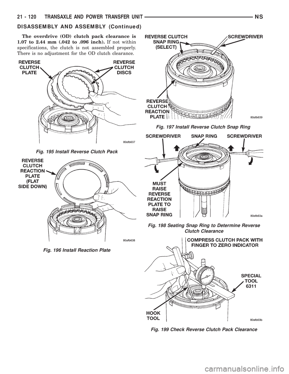
The overdrive (OD) clutch pack clearance is
1.07 to 2.44 mm (.042 to .096 inch).If not within
specifications, the clutch is not assembled properly.
There is no adjustment for the OD clutch clearance.
Fig. 195 Install Reverse Clutch Pack
Fig. 196 Install Reaction Plate
Fig. 197 Install Reverse Clutch Snap Ring
Fig. 198 Seating Snap Ring to Determine Reverse
Clutch Clearance
Fig. 199 Check Reverse Clutch Pack Clearance
21 - 120 TRANSAXLE AND POWER TRANSFER UNITNS
DISASSEMBLY AND ASSEMBLY (Continued)
Page 1599 of 1938
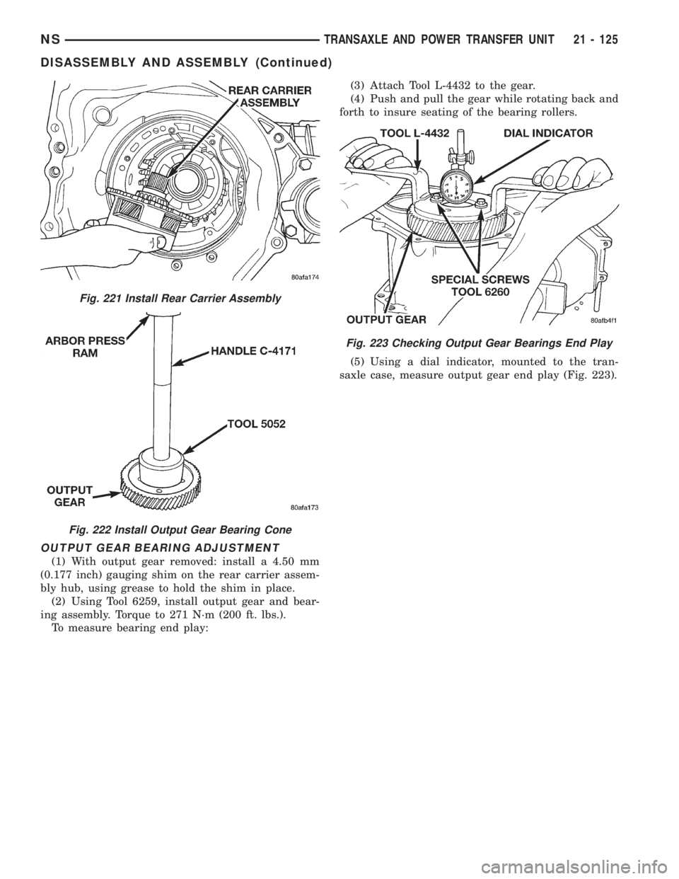
OUTPUT GEAR BEARING ADJUSTMENT
(1) With output gear removed: install a 4.50 mm
(0.177 inch) gauging shim on the rear carrier assem-
bly hub, using grease to hold the shim in place.
(2) Using Tool 6259, install output gear and bear-
ing assembly. Torque to 271 N´m (200 ft. lbs.).
To measure bearing end play:(3) Attach Tool L-4432 to the gear.
(4) Push and pull the gear while rotating back and
forth to insure seating of the bearing rollers.
(5) Using a dial indicator, mounted to the tran-
saxle case, measure output gear end play (Fig. 223).
Fig. 221 Install Rear Carrier Assembly
Fig. 222 Install Output Gear Bearing Cone
Fig. 223 Checking Output Gear Bearings End Play
NSTRANSAXLE AND POWER TRANSFER UNIT 21 - 125
DISASSEMBLY AND ASSEMBLY (Continued)
Page 1608 of 1938
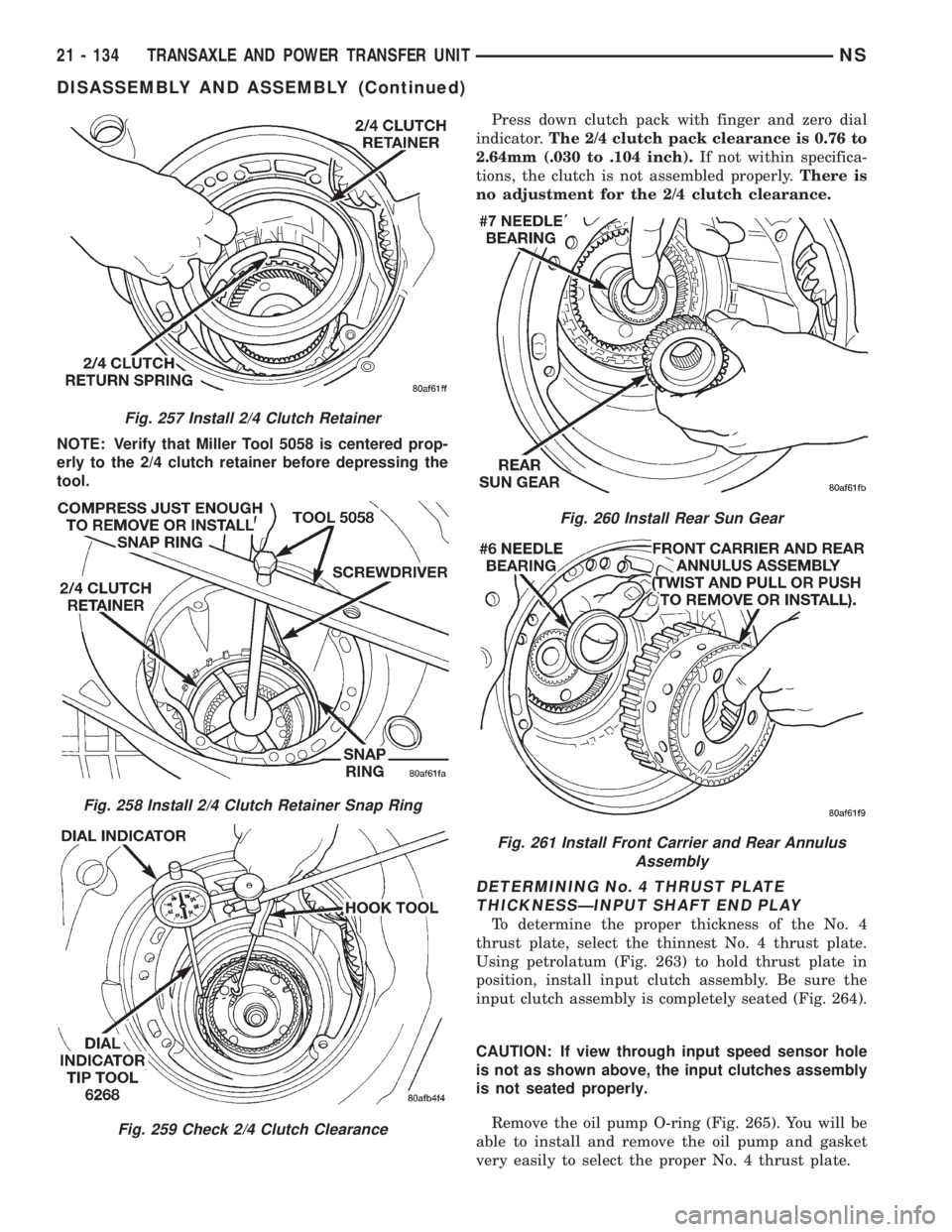
NOTE: Verify that Miller Tool 5058 is centered prop-
erly to the 2/4 clutch retainer before depressing the
tool.Press down clutch pack with finger and zero dial
indicator.The 2/4 clutch pack clearance is 0.76 to
2.64mm (.030 to .104 inch).If not within specifica-
tions, the clutch is not assembled properly.There is
no adjustment for the 2/4 clutch clearance.
DETERMINING No. 4 THRUST PLATE
THICKNESSÐINPUT SHAFT END PLAY
To determine the proper thickness of the No. 4
thrust plate, select the thinnest No. 4 thrust plate.
Using petrolatum (Fig. 263) to hold thrust plate in
position, install input clutch assembly. Be sure the
input clutch assembly is completely seated (Fig. 264).
CAUTION: If view through input speed sensor hole
is not as shown above, the input clutches assembly
is not seated properly.
Remove the oil pump O-ring (Fig. 265). You will be
able to install and remove the oil pump and gasket
very easily to select the proper No. 4 thrust plate.
Fig. 257 Install 2/4 Clutch Retainer
Fig. 258 Install 2/4 Clutch Retainer Snap Ring
Fig. 259 Check 2/4 Clutch Clearance
Fig. 260 Install Rear Sun Gear
Fig. 261 Install Front Carrier and Rear Annulus
Assembly
21 - 134 TRANSAXLE AND POWER TRANSFER UNITNS
DISASSEMBLY AND ASSEMBLY (Continued)
Page 1616 of 1938
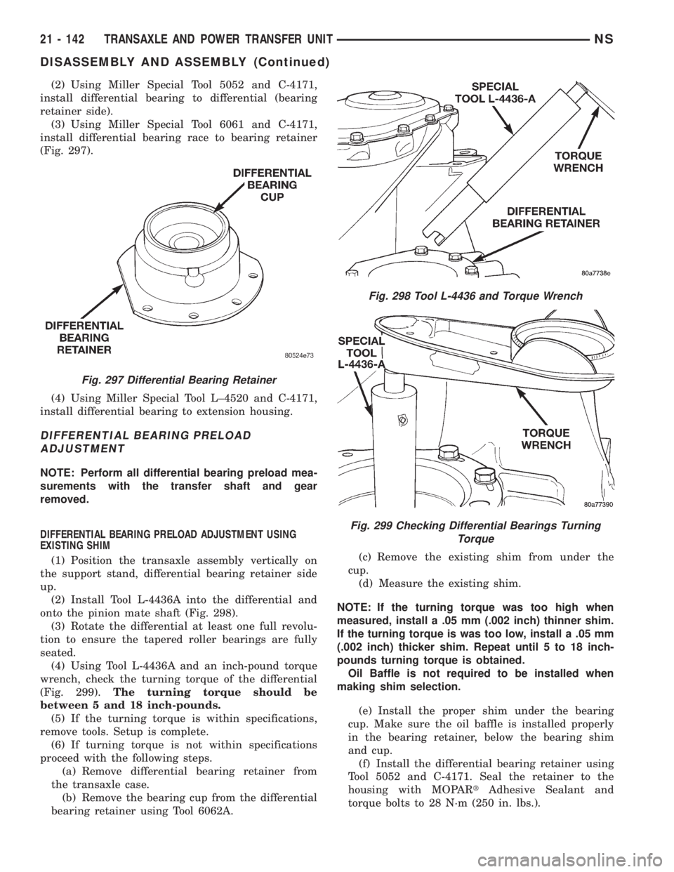
(2) Using Miller Special Tool 5052 and C-4171,
install differential bearing to differential (bearing
retainer side).
(3) Using Miller Special Tool 6061 and C-4171,
install differential bearing race to bearing retainer
(Fig. 297).
(4) Using Miller Special Tool L±4520 and C-4171,
install differential bearing to extension housing.
DIFFERENTIAL BEARING PRELOAD
ADJUSTMENT
NOTE: Perform all differential bearing preload mea-
surements with the transfer shaft and gear
removed.
DIFFERENTIAL BEARING PRELOAD ADJUSTMENT USING
EXISTING SHIM
(1) Position the transaxle assembly vertically on
the support stand, differential bearing retainer side
up.
(2) Install Tool L-4436A into the differential and
onto the pinion mate shaft (Fig. 298).
(3) Rotate the differential at least one full revolu-
tion to ensure the tapered roller bearings are fully
seated.
(4) Using Tool L-4436A and an inch-pound torque
wrench, check the turning torque of the differential
(Fig. 299).The turning torque should be
between 5 and 18 inch-pounds.
(5) If the turning torque is within specifications,
remove tools. Setup is complete.
(6) If turning torque is not within specifications
proceed with the following steps.
(a) Remove differential bearing retainer from
the transaxle case.
(b) Remove the bearing cup from the differential
bearing retainer using Tool 6062A.(c) Remove the existing shim from under the
cup.
(d) Measure the existing shim.
NOTE: If the turning torque was too high when
measured, install a .05 mm (.002 inch) thinner shim.
If the turning torque is was too low, install a .05 mm
(.002 inch) thicker shim. Repeat until 5 to 18 inch-
pounds turning torque is obtained.
Oil Baffle is not required to be installed when
making shim selection.
(e) Install the proper shim under the bearing
cup. Make sure the oil baffle is installed properly
in the bearing retainer, below the bearing shim
and cup.
(f) Install the differential bearing retainer using
Tool 5052 and C-4171. Seal the retainer to the
housing with MOPARtAdhesive Sealant and
torque bolts to 28 N´m (250 in. lbs.).
Fig. 297 Differential Bearing Retainer
Fig. 298 Tool L-4436 and Torque Wrench
Fig. 299 Checking Differential Bearings Turning
Torque
21 - 142 TRANSAXLE AND POWER TRANSFER UNITNS
DISASSEMBLY AND ASSEMBLY (Continued)
Page 1617 of 1938
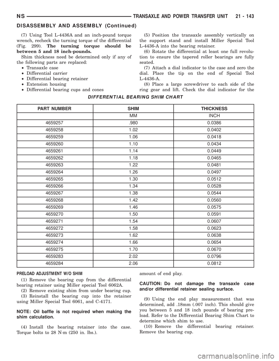
(7) Using Tool L-4436A and an inch-pound torque
wrench, recheck the turning torque of the differential
(Fig. 299).The turning torque should be
between 5 and 18 inch-pounds.
Shim thickness need be determined only if any of
the following parts are replaced:
²Transaxle case
²Differential carrier
²Differential bearing retainer
²Extension housing
²Differential bearing cups and cones
PRELOAD ADJUSTMENT W/O SHIM
(1) Remove the bearing cup from the differential
bearing retainer using Miller special Tool 6062A.
(2) Remove existing shim from under bearing cup.
(3) Reinstall the bearing cup into the retainer
using Miller Special Tool 6061, and C-4171.
NOTE: Oil baffle is not required when making the
shim calculation.
(4) Install the bearing retainer into the case.
Torque bolts to 28 N´m (250 in. lbs.).(5) Position the transaxle assembly vertically on
the support stand and install Miller Special Tool
L-4436-A into the bearing retainer.
(6) Rotate the differential at least one full revolu-
tion to ensure the tapered roller bearings are fully
seated.
(7) Attach a dial indicator to the case and zero the
dial. Place the tip on the end of Special Tool
L-4436-A.
(8) Place a large screwdriver to each side of the
ring gear and lift. Check the dial indicator for the
amount of end play.
CAUTION: Do not damage the transaxle case
and/or differential retainer sealing surface.
(9) Using the end play measurement that was
determined, add .18mm (.007 inch). This should give
you between 5 and 18 inch pounds of bearing pre-
load. Refer to the Differential Bearing Shim Chart to
determine which shim to use.
(10) Remove the differential bearing retainer.
Remove the bearing cup.
DIFFERENTIAL BEARING SHIM CHART
PART NUMBER SHIM THICKNESS
MM INCH
4659257 .980 0.0386
4659258 1.02 0.0402
4659259 1.06 0.0418
4659260 1.10 0.0434
4659261 1.14 0.0449
4659262 1.18 0.0465
4659263 1.22 0.0481
4659264 1.26 0.0497
4659265 1.30 0.0512
4659266 1.34 0.0528
4659267 1.38 0.0544
4659268 1.42 0.0560
4659269 1.46 0.0575
4659270 1.50 0.0591
4659271 1.54 0.0607
4659272 1.58 0.0623
4659273 1.62 0.0638
4659274 1.66 0.0654
4659275 1.70 0.0670
4659283 2.02 0.0796
4659284 2.06 0.0812
NSTRANSAXLE AND POWER TRANSFER UNIT 21 - 143
DISASSEMBLY AND ASSEMBLY (Continued)
Page 1708 of 1938
REVERSE SHIFT LEVER
REMOVAL
(1) Remove reverse shift lever E-clip.
(2) Remove the flat and wave washers.
(3) Remove the reverse shift lever from the mount-
ing stud.
INSTALLATION
(1) Position the reverse shift lever onto the mount-
ing stud.
(2) Install the washers onto the mounting stud.
(3) Install the E-clip.
CLEANING AND INSPECTION
TRANSAXLE
Clean the gears, bearings, shafts, synchronizers,
thrust washers, oil feeder, shift mechanism, gear
case, and bellhousing with solvent. Dry all parts
except the bearings with compressed air. Allow thebearings to either air dry or wipe them dry with
clean shop towels.
Inspect the gears, bearings, shafts and thrust
washers. Replace the bearings and cups if the rollers
are worn, chipped, cracked, flat spotted, or brin-
nelled, or if the bearing cage is damaged or distorted.
Replace the thrust washers if cracked, chipped, or
worn. Replace the gears if the teeth are chipped,
cracked, or worn thin. Inspect the synchronizers.
Replace the sleeve if worn or damaged in any way.
Replace the stop rings if the friction material is
burned, flaking off, or worn. Check the condition of
the synchro struts and springs. Replace these parts if
worn, cracked, or distorted.
SYNCHRONIZER
CLEAN
Do not attempt to clean the blocking rings in sol-
vent. The friction material will become contaminated.
Place synchronizer components in a suitable holder
and clean with solvent. Air dry.
INSPECT
Proper inspection of components involve:
²Teeth, for wear, scuffed, nicked, burred, or bro-
ken teeth
²Struts, for wear or distortion
²Springs, for distortion, cracks, or wear
If any of these conditions exist in these compo-
nents, replace as necessary.
ADJUSTMENTS
GEARSHIFT CROSSOVER CABLE
Before replacing the gearshift cables for a hard-
shifting complaint, disconnect both cables at the
transaxle. Then, from the driver's seat, manually
operate the gearshift lever through all gear ranges. If
the gearshift lever moves smoothly, the cable(s)
should NOT be replaced. If the gear lever binds
replace the cable that is causing the binding condi-
tion. If the problem still exists, check the crossover
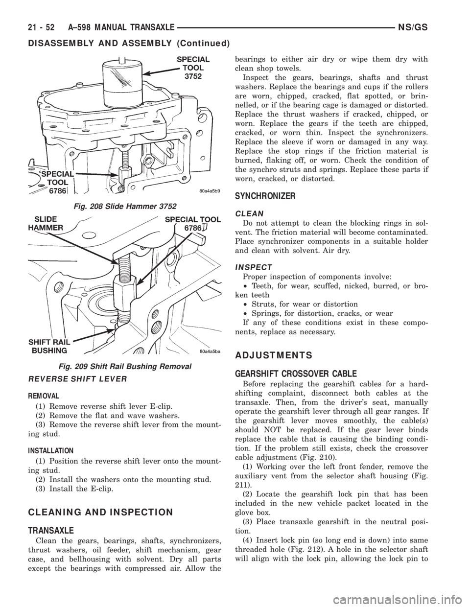
cable adjustment (Fig. 210).
(1) Working over the left front fender, remove the
auxiliary vent from the selector shaft housing (Fig.
211).
(2) Locate the gearshift lock pin that has been
included in the new vehicle packet located in the
glove box.
(3) Place transaxle gearshift in the neutral posi-
tion.
(4) Insert lock pin (so long end is down) into same
threaded hole (Fig. 212). A hole in the selector shaft
will align with the lock pin, allowing the lock pin to
Fig. 208 Slide Hammer 3752
Fig. 209 Shift Rail Bushing Removal
21 - 52 A±598 MANUAL TRANSAXLENS/GS
DISASSEMBLY AND ASSEMBLY (Continued)
Page 1711 of 1938
GEARSHIFT CROSSOVER CABLE
Before replacing the gearshift cables for a hard-
shifting complaint, disconnect both cables at the
transaxle. Then, from the driver's seat, manually
operate the gearshift lever through all gear ranges. If
the gearshift lever moves smoothly, the cable(s)
should NOT be replaced. If the gear lever binds
replace the cable that is causing the binding condi-
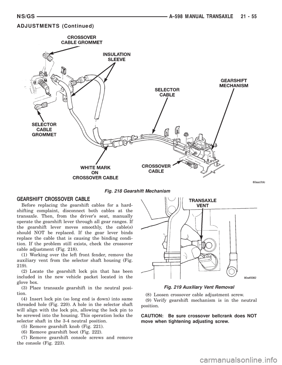
tion. If the problem still exists, check the crossover
cable adjustment (Fig. 218).
(1) Working over the left front fender, remove the
auxiliary vent from the selector shaft housing (Fig.
219).
(2) Locate the gearshift lock pin that has been
included in the new vehicle packet located in the
glove box.
(3) Place transaxle gearshift in the neutral posi-
tion.
(4) Insert lock pin (so long end is down) into same
threaded hole (Fig. 220). A hole in the selector shaft
will align with the lock pin, allowing the lock pin to
be screwed into the housing. This operation locks the
selector shaft in the 3-4 neutral position.
(5) Remove gearshift knob (Fig. 221).
(6) Remove gearshift boot (Fig. 222).
(7) Remove gearshift console screws and remove
the console (Fig. 223).(8) Loosen crossover cable adjustment screw.
(9) Verify gearshift mechanism is in the neutral
position.
CAUTION: Be sure crossover bellcrank does NOT
move when tightening adjusting screw.
Fig. 218 Gearshift Mechanism
Fig. 219 Auxiliary Vent Removal
NS/GSA±598 MANUAL TRANSAXLE 21 - 55
ADJUSTMENTS (Continued)
Page 1713 of 1938
been replaced, you must perform the differential
bearing preload shim adjustment. If the transaxle
case has been replaced, you must perform both pro-
cedures.
GENERAL RULES ON SERVICING BEARINGS
(1) Use extreme care when removing and install-
ing bearing cups and cones. Burrs or nicks on the
bearing seat will give a false end play reading while
gauging for proper shims. Improperly seated bearing
cups and cones are subject to low±mileage failure.
(2) Bearing cups and cones should be replaced if
they show signs of pitting or heat distress. If distress
is seen on either the cup or bearing rollers, both cup
and cone must be replaced.(3) Bearing preload and drag torque specifications
must be maintained to avoid premature bearing fail-
ures. Used (original) bearings may lose up to 50% of
their original drag torque after break in. All bearing
adjustments must be made with no other component
interference or gear intermesh.
(4) Replace bearings as a pair: If one differential
bearing is defective, replace both differential bear-
ings.
(5) Bearing cones must not be reused if removed.
(6) Turning torque readings should be obtained
while smoothly rotating in either direction.
INTERMEDIATE SHAFT BEARING PRELOAD
The intermediate shaft preload must be checked if
the housing, intermediate shaft, bearing plate, bear-
ings, or transaxle case are replaced.
The intermediate shaft bearing preload procedure
must be done with the transaxle out of the vehicle
and on a bench.
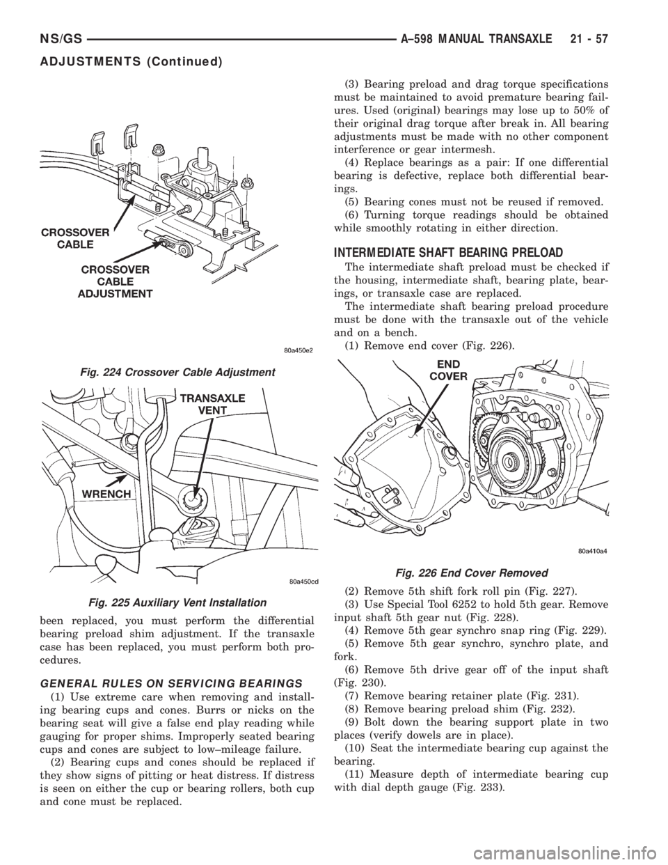
(1) Remove end cover (Fig. 226).
(2) Remove 5th shift fork roll pin (Fig. 227).
(3) Use Special Tool 6252 to hold 5th gear. Remove
input shaft 5th gear nut (Fig. 228).
(4) Remove 5th gear synchro snap ring (Fig. 229).
(5) Remove 5th gear synchro, synchro plate, and
fork.
(6) Remove 5th drive gear off of the input shaft
(Fig. 230).
(7) Remove bearing retainer plate (Fig. 231).
(8) Remove bearing preload shim (Fig. 232).
(9) Bolt down the bearing support plate in two
places (verify dowels are in place).
(10) Seat the intermediate bearing cup against the
bearing.
(11) Measure depth of intermediate bearing cup
with dial depth gauge (Fig. 233).
Fig. 224 Crossover Cable Adjustment
Fig. 225 Auxiliary Vent Installation
Fig. 226 End Cover Removed
NS/GSA±598 MANUAL TRANSAXLE 21 - 57
ADJUSTMENTS (Continued)