1996 CHRYSLER VOYAGER seat adjustment
[x] Cancel search: seat adjustmentPage 513 of 1938

REMOTE KEYLESS ENTRY
INDEX
page page
DESCRIPTION AND OPERATION
INTRODUCTION......................... 5
VEHICLE ACCESS CODE (VAC)
PROGRAMMING........................ 5
DIAGNOSIS AND TESTING
RKE DIAGNOSTICS....................... 5
SERVICE PROCEDURES
HORN CHIRP DISABLE OR ENABLE.......... 6REMOVAL AND INSTALLATION
RKE MODULE........................... 6
ADJUSTMENTS
PROGRAMMING RKE MODULE.............. 6
SPECIFICATIONS
RKE TRANSMITTER BATTERY.............. 6
RKE TRANSMITTER RANGE................ 6
DESCRIPTION AND OPERATION
INTRODUCTION
The key fob transmitter has three buttons to actu-
ate and program the Remote Keyless Entry (RKE)
system (Fig. 1).
²UNLOCK: Pressing the UNLOCK button once
will unlock the driver door and activate the illumi-
nated entry system and disarm Vehicle Theft Secu-
rity System, if equipped. Pressing the UNLOCK
button twice within five seconds will unlock all doors
and activate the illuminated entry system.
²LOCK: Pressing the LOCK button locks all
doors and sounds horn (chirp) and arm the Vehicle
Theft Security System. The chirp verifies the door
lock operation.
²PANIC: Pressing the PANIC button sounds the
horns at half second intervals, flashes the exterior
lamps, and turns ON the interior lamps. The panic
alarm will remain on for three minutes, or until the
PANIC button is actuated again or the ignition
switch is turned to the RUN position.
²The Remote Keyless Entry Module is capable of
retaining the transmitter Vehicle Access Code(s)
(VAC) in its memory even after vehicle power has
been interrupted.
²The RKE system activates the optional memory
seat and mirror system, if equipped. Two primary
key fob transmitters can be programmed to actuate
memory seat and mirror setting 1 or 2. Two addi-
tional key fob transmitters can be added, but they
will not be able to operate the memory seat and mir-
ror system. Refer to Group 8R, Power Seats and
Group 8T, Power Mirrors for memory system infor-
mation.
VEHICLE ACCESS CODE (VAC) PROGRAMMING
The RKE module is capable of retaining up to four
different Vehicle Access Codes. Whenever the vehicle
battery power is interrupted the RKE Module willretain all vehicle access codes in its memory. When
replacing or adding a key fob transmitter (maximum
4) a functional key fob transmitter is required to pro-
gram the RKE Module to accept the new Vehicle
Access Code. If a functional key fob transmitter is
not available, a scan tool (DRB) can be used to pro-
gram the RKE Module. Refer to the proper Body
Diagnostic Procedures manual for Vehicle Access
Code programming procedures using a scan tool.
DIAGNOSIS AND TESTING
RKE DIAGNOSTICS
Refer to Group 8W, Wiring Diagrams for circuit
information and component locations. Refer to the
proper Body Diagnostic Procedures manual for test-
ing the Remote Keyless Entry system using a scan
tool (DRB). Also refer to other interrelated systems
groups within this manual:
²Group 8Q, Vehicle Theft Security System
²Group 8R, Power Seats
²Group 8T, Power Mirrors
Fig. 1 Key Fob Transmitter
NSPOWER DOOR LOCKS 8P - 5
Page 514 of 1938

SERVICE PROCEDURES
HORN CHIRP DISABLE OR ENABLE
The horn chirp can be DISABLED or ENABLED
using the following procedure.
To DISABLE (cancelling) the horn chirp feature,
press and hold the transmitter LOCK button for a
minimum four seconds. While pressing LOCK button
in, press the UNLOCK button. The horn chirp fea-
ture will not function until the above procedure is
repeated. To ENABLE (reinstate) the horn chirp fea-
ture, use any one of the four key fob transmitters
and reverse the above procedures. It will ENABLE
the horn chirp feature for all transmitters.
REMOVAL AND INSTALLATION
RKE MODULE
REMOVAL
(1) Remove instrument panel top cover. Refer to
Group 8E, Instrument Panel and Gauges for proper
procedures.
(2) Remove screws holding RKE module to instru-
ment panel.
(3) Disconnect wire connector from RKE module
(Fig. 2).
(4) Remove the RKE module.
INSTALLATION
For installation, reverse the above procedures.
ADJUSTMENTS
PROGRAMMING RKE MODULE
(1) Using a functional key fob transmitter, unlock
the vehicle and disarm the Vehicle Theft Security
System.
(2) Insert ignition key into the ignition switch.
(3) Turn the ignition switch to RUN position with-
out starting engine.
(4) Using a functional key fob transmitter, press
and hold the UNLOCK button for a minimum four
seconds (maximum ten seconds).
(5) While holding UNLOCK button, and before ten
seconds passes, press and release the PANIC button.
A single chime will sound to verify that the RKE
module is set to receive the new Vehicle Access
Code(s).
(6) Within 30 seconds of the chime, press any but-
ton on each new key fob transmitter. After 30 sec-
onds or when ignition switch is turned OFF, the RKE
module will end the programming mode. A single
chime will sound to verify that the RKE module will
no longer receive additional Vehicle Access Code(s).
(7) When Vehicle Access Code(s) programming is
complete, turn Ignition Switch to the OFF position
and verify RKE system operation using each key fob.
NOTE: Only the primary (first two) key fob transmit-
ters will operate the memory seat and mirror sys-
tems. If a primary key fob is being replaced, the
memory seat and mirror module will require pro-
gramming. Refer to Group 8R, Power Seats for
proper (data link) programming procedure.
SPECIFICATIONS
RKE TRANSMITTER BATTERY
The batteries can be removed without special tools
and are readily available at local retail stores. The
recommended battery is Duracell DL 2016 or equiva-
lent. Battery life is about one to two years.
CAUTION: Do not touch the battery terminals or
handle the batteries any more than necessary.
Hands must be clean and dry.
RKE TRANSMITTER RANGE
Normal operation range is up to about a distance
of 7 meters (23 ft.) of the vehicle. Range may be bet-
ter or worse depending on the environment around
the vehicle. Closeness to a radio frequency transmit-
ter such as a radio station tower may degrade oper-
ational range, while range in an open field will be
enhanced.
Fig. 2 RKE Module
8P - 6 POWER DOOR LOCKSNS
Page 1058 of 1938
cause of low compression unless some malfunc-
tion is present.
(11) Clean or replace spark plugs as necessary
and adjust gap as specified in Group 8, Electrical.
Tighten to specifications.
(12) Test resistance of spark plug cables. Refer to
Group 8, Electrical Ignition System Secondary Cir-
cuit Inspection.
(13) Test coil output voltage, primary and second-
ary resistance. Replace parts as necessary. Refer to
Group 8, Electrical Ignition System.
(14) Check fuel pump pressure at idle and differ-
ent RPM ranges. Refer to Group 14, Fuel System for
Specifications.
(15) The air filter elements should be replaced as
specified in Group 0, Lubrication and Maintenance,.
(16) Inspect crankcase ventilation system as out
lined in Group 0, Lubrication and Maintenance. For
emission controls see Group 25, Emission Controls
for service procedures.
(17) Inspect and adjust accessory belt drives refer-
ring to Group 7, Cooling System, Accessory Drive
Belts for proper adjustments.
(18) Road test vehicle as a final test.
CYLINDER COMBUSTION PRESSURE LEAKAGE
TEST
The combustion pressure leakage test provides an
accurate means for determining engine condition.
Combustion pressure leakage testing will detect:
²Exhaust and intake valve leaks (improper seat-
ing).
²Leaks between adjacent cylinders or into water
jacket.
²Any causes for combustion/compression pressure
loss.
WARNING: DO NOT REMOVE THE RADIATOR CAP
WITH THE SYSTEM HOT AND UNDER PRESSURE
BECAUSE SERIOUS BURNS FROM COOLANT CAN
OCCUR.
Check the coolant level and fill as required. DO
NOT install the radiator cap.
Start and operate the engine until it attains nor-
mal operating temperature, then turn the engine
OFF.
Clean spark plug recesses with compressed air.
Remove the spark plugs.
Remove the oil filler cap.
Remove the air cleaner.
Calibrate the tester according to the manufactur-
er's instructions. The shop air source for testing
should maintain 483 kPa (70 psi) minimum, 1 379
kPa (200 psi) maximum and 552 kPa (80 psi) recom-
mended.Perform the test procedures on each cylinder
according to the tester manufacturer's instructions.
While testing, listen for pressurized air escaping
through the throttle body, tailpipe and oil filler cap
opening. Check for bubbles in the radiator coolant.
All gauge pressure indications should be equal,
with no more than 25% leakage.
FOR EXAMPLE:At 552 kPa (80 psi) input pres-
sure, a minimum of 414 kPa (60 psi) should be main-
tained in the cylinder.
LASH ADJUSTER (TAPPET) NOISE DIAGNOSIS
A tappet-like noise may be produced from several
items. Check the following items.
(1) Engine oil level too high or too low. This may
cause aerated oil to enter the adjusters and cause
them to be spongy.
(2) Insufficient running time after rebuilding cylin-
der head. Low speed running up to 1 hour may be
required.
(3) During this time, turn engine off and let set for
a few minutes before restarting. Repeat this several
times after engine has reached normal operating
temperature.
(4) Low oil pressure.
(5) The oil restrictor pressed into the vertical oil
passage to the cylinder head is plugged with debris.
(6) Air ingested into oil due to broken or cracked
oil pump pick up.
(7) Worn valve guides.
(8) Rocker arm ears contacting valve spring
retainer.
(9) Rocker arm loose, adjuster stuck or at maxi-
mum extension and still leaves lash in the system.
(10) Faulty lash adjuster.
a. Check lash adjusters for sponginess while
installed in cylinder head. Depress part of rocker
arm over adjuster. Normal adjusters should feel very
firm. Spongy adjusters can be bottomed out easily.
b. Remove suspected lash adjusters, and disassem-
bleDo not reuse retainer caps. Do not inter-
change parts and make sure that care and
cleanliness is exercised in the handling of parts.
c. Clean out dirt and varnish with solvent.
d. Reassemble with engine oil.
e. Check for sponginess.
f. If still spongy, replace with new adjuster.
INSPECTION (ENGINE OIL LEAKS IN GENERAL)
Begin with a through visual inspection of the
engine, particularly at the area of the suspected leak.
If an oil leak source is not readily identifiable, the
following steps should be followed:
(1) Do not clean or degrease the engine at this
time because some solvents may cause rubber to
swell, temporarily stopping the leak.
9 - 8 ENGINENS
DIAGNOSIS AND TESTING (Continued)
Page 1083 of 1938
NOTE: THE TIMING MARK ON THE SPROCKET,
THE (LOWER) NICKEL PLATED LINK, AND THE
ARROW ON THE SIDE OF THE GEAR COVER
SHOULD LINE UP WHEN THE BALANCE SHAFTS
ARE TIMED CORRECTLY.
(9) If the sprockets are timed correctly install the
balance shaft bolts and tighten to 28 N´m (250 in.
lbs.). A wood block placed between crankcase and
crankshaft counterbalance will prevent crankshaft
and gear rotation.
CHAIN TENSIONING
(1) Install chain tensioner loosely assembled.
(2) Position guide on double ended stud making
sure tab on the guide fits into slot on the gear cover.
Install and tighten nut/washer assembly to 12 N´m
(105 in. lbs.).
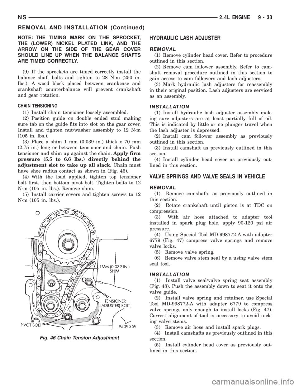
(3) Place a shim 1 mm (0.039 in.) thick x 70 mm
(2.75 in.) long or between tensioner and chain. Push
tensioner and shim up against the chain.Apply firm
pressure (5.5 to 6.6 lbs.) directly behind the
adjustment slot to take up all slack.Chain must
have shoe radius contact as shown in (Fig. 46).
(4) With the load applied, tighten top tensioner
bolt first, then bottom pivot bolt. Tighten bolts to 12
N´m (105 in. lbs.). Remove shim.
(5) Install carrier covers and tighten screws to 12
N´m (105 in. lbs.).HYDRAULIC LASH ADJUSTER
REMOVAL
(1) Remove cylinder head cover. Refer to procedure
outlined in this section.
(2) Remove cam follower assembly. Refer to cam-
shaft removal procedure outlined in this section to
gain access to cam followers and lash adjusters.
(3) Mark hydraulic lash adjusters for reassembly
in their original position. Lash adjusters are serviced
as an assembly.
INSTALLATION
(1) Install hydraulic lash adjuster assembly mak-
ing sure adjusters are at least partially full of oil.
This is indicated by little or no plunger travel when
the lash adjuster is depressed.
(2) Install cam follower assembly as previously
outlined in this section.
(3) Install camshaft as previously outlined in this
section.
(4) Install cylinder head cover as previously out-
lined in this section.
VALVE SPRINGS AND VALVE SEALS IN VEHICLE
REMOVAL
(1) Remove camshafts as previously outlined in
this section.
(2) Rotate crankshaft until piston is at TDC on
compression.
(3) With air hose attached to adapter tool
installed in spark plug hole, apply 90-120 psi air
pressure.
(4) Using Special Tool MD-998772-A with adapter
6779 (Fig. 47) compress valve springs and remove
valve locks.
(5) Remove valve spring.
(6) Remove valve stem seal by a using valve stem
seal tool.
INSTALLATION
(1) Install valve seal/valve spring seat assembly
(Fig. 48). Push the assembly down to seat it onto the
valve guide.
(2) Install valve spring and retainer, use Special
Tool MD-998772-A with adapter 6779 to compress
valve springs only enough to install locks (Fig. 47).
Correct alignment of tool is necessary to avoid nick-
ing valve stems.
(3) Remove air hose and install spark plugs.
(4) Install camshafts as previously outlined in this
section.
(5) Install cylinder head cover as previously out-
lined in this section.
Fig. 46 Chain Tension Adjustment
NS2.4L ENGINE 9 - 33
REMOVAL AND INSTALLATION (Continued)
Page 1208 of 1938
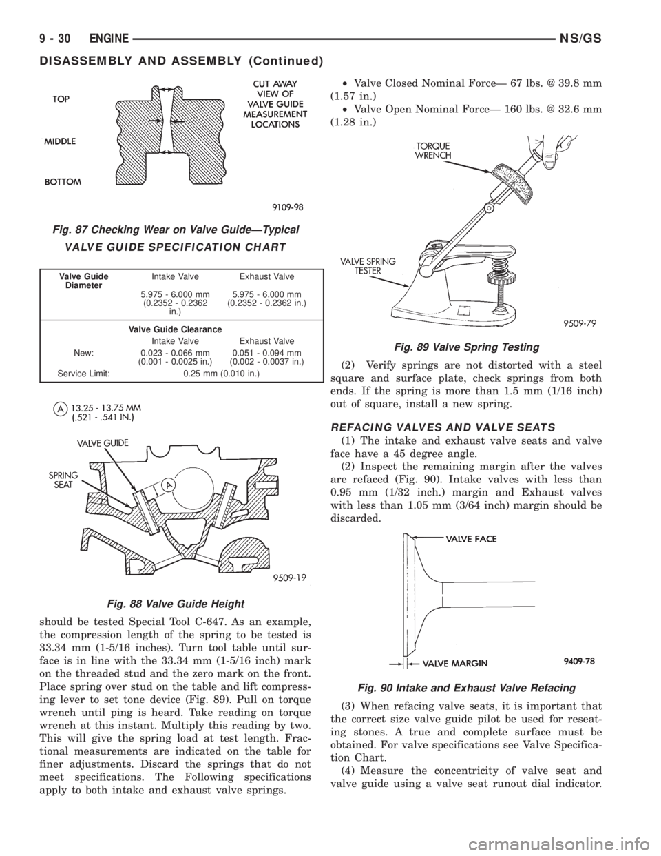
should be tested Special Tool C-647. As an example,
the compression length of the spring to be tested is
33.34 mm (1-5/16 inches). Turn tool table until sur-
face is in line with the 33.34 mm (1-5/16 inch) mark
on the threaded stud and the zero mark on the front.
Place spring over stud on the table and lift compress-
ing lever to set tone device (Fig. 89). Pull on torque
wrench until ping is heard. Take reading on torque
wrench at this instant. Multiply this reading by two.
This will give the spring load at test length. Frac-
tional measurements are indicated on the table for
finer adjustments. Discard the springs that do not
meet specifications. The Following specifications
apply to both intake and exhaust valve springs.²Valve Closed Nominal ForceÐ 67 lbs. @ 39.8 mm
(1.57 in.)
²Valve Open Nominal ForceÐ 160 lbs. @ 32.6 mm
(1.28 in.)
(2) Verify springs are not distorted with a steel
square and surface plate, check springs from both
ends. If the spring is more than 1.5 mm (1/16 inch)
out of square, install a new spring.
REFACING VALVES AND VALVE SEATS
(1) The intake and exhaust valve seats and valve
face have a 45 degree angle.
(2) Inspect the remaining margin after the valves
are refaced (Fig. 90). Intake valves with less than
0.95 mm (1/32 inch.) margin and Exhaust valves
with less than 1.05 mm (3/64 inch) margin should be
discarded.
(3) When refacing valve seats, it is important that
the correct size valve guide pilot be used for reseat-
ing stones. A true and complete surface must be
obtained. For valve specifications see Valve Specifica-
tion Chart.
(4) Measure the concentricity of valve seat and
valve guide using a valve seat runout dial indicator.
Fig. 87 Checking Wear on Valve GuideÐTypical
VALVE GUIDE SPECIFICATION CHART
Valve Guide
DiameterIntake Valve Exhaust Valve
5.975 - 6.000 mm
(0.2352 - 0.2362
in.)5.975 - 6.000 mm
(0.2352 - 0.2362 in.)
Valve Guide Clearance
Intake Valve Exhaust Valve
New: 0.023 - 0.066 mm
(0.001 - 0.0025 in.)0.051 - 0.094 mm
(0.002 - 0.0037 in.)
Service Limit: 0.25 mm (0.010 in.)
Fig. 88 Valve Guide Height
Fig. 89 Valve Spring Testing
Fig. 90 Intake and Exhaust Valve Refacing
9 - 30 ENGINENS/GS
DISASSEMBLY AND ASSEMBLY (Continued)
Page 1526 of 1938
(3) Back off adjusting screw the number of turns
listed in Specifications. Hold adjusting screw in this
position and tighten locknut to 47 N´m (35ft. lbs.)
LOW/REVERSE BAND (REAR)
To adjust low-reverse band, proceed as follows:
(1) Loosen and back off locknut approximately 5
turns.
(2) Using an inch-pound torque wrench, tighten
adjusting screw to 5 N´m (41 in. lbs.) true torque.
(3) Back off adjusting screw the number of turns
listed under Specifications. This chart is located at
the rear of this section.
(4) Tighten locknut to 14 N´m (10 ft. lbs.).
HYDRAULIC CONTROL PRESSURE ADJUSTMENTS
LINE PRESSURE
An incorrect throttle pressure setting will cause
incorrect line pressure readings even though line
pressure adjustment is correct. Always inspect and
correct throttle pressure adjustment before adjusting
the line pressure.
The approximate adjustment for line pressure is
1-5/16 inches, measured from valve body to inner
edge of adjusting nut. However, due to manufactur-
ing tolerances, the adjustment can be varied to
obtain specified line pressure.
The adjusting screw may be turned with an Allen
wrench. One complete turn of adjusting screw
changes closed throttle line pressure approximately
1-2/3 psi. Turning adjusting screw counterclockwise
increases pressure, and clockwise decreases pressure.
THROTTLE PRESSURE
Throttle pressures cannot be tested accurately;
therefore, the adjustment should be measured if a
malfunction is evident.
(1) Insert gauge pin of Tool C-3763 between the
throttle lever cam and kickdown valve.
(2) By pushing in on tool, compress kickdown
valve against its spring so throttle valve is com-
pletely bottomed inside the valve body.
(3) While compressing spring, turn throttle lever
stop screw with adapter C-4553. Turn until head of
screw touches throttle lever tang, with throttle lever
cam touching tool and throttle valve bottomed. Be
sure adjustment is made with spring fully com-
pressed and valve bottomed in the valve body.
BEARING ADJUSTMENT PROCEDURES
(1) Take extreme care when removing and install-
ing bearing cups and cones.Use only an arbor
press for installation, as a hammer may not
properly align the bearing cup or cone.Burrs or
nicks on the bearing seat will give a false end play
reading, while gauging for proper shims. Improperlyseated bearing cup and cones are subject to low-mile-
age failure.
(2) Bearing cups and cones should be replaced if
they show signs of pitting or heat distress.
(3) If distress is seen on either the cup or bearing
rollers, both cup and cone must be replaced.
NOTE: Bearing end play and drag torque specifica-
tions must be maintained to avoid premature bear-
ing failures.
(4) Used (original) bearing may lose up to 50 per-
cent of the original drag torque after break-in.
NOTE: All bearing adjustments must be made with
no other component interference or gear inter-
mesh, except the transfer gear bearing.
(5) Refer to the conversion chart in specifications
to convert inches to millimeter measurements. Refer
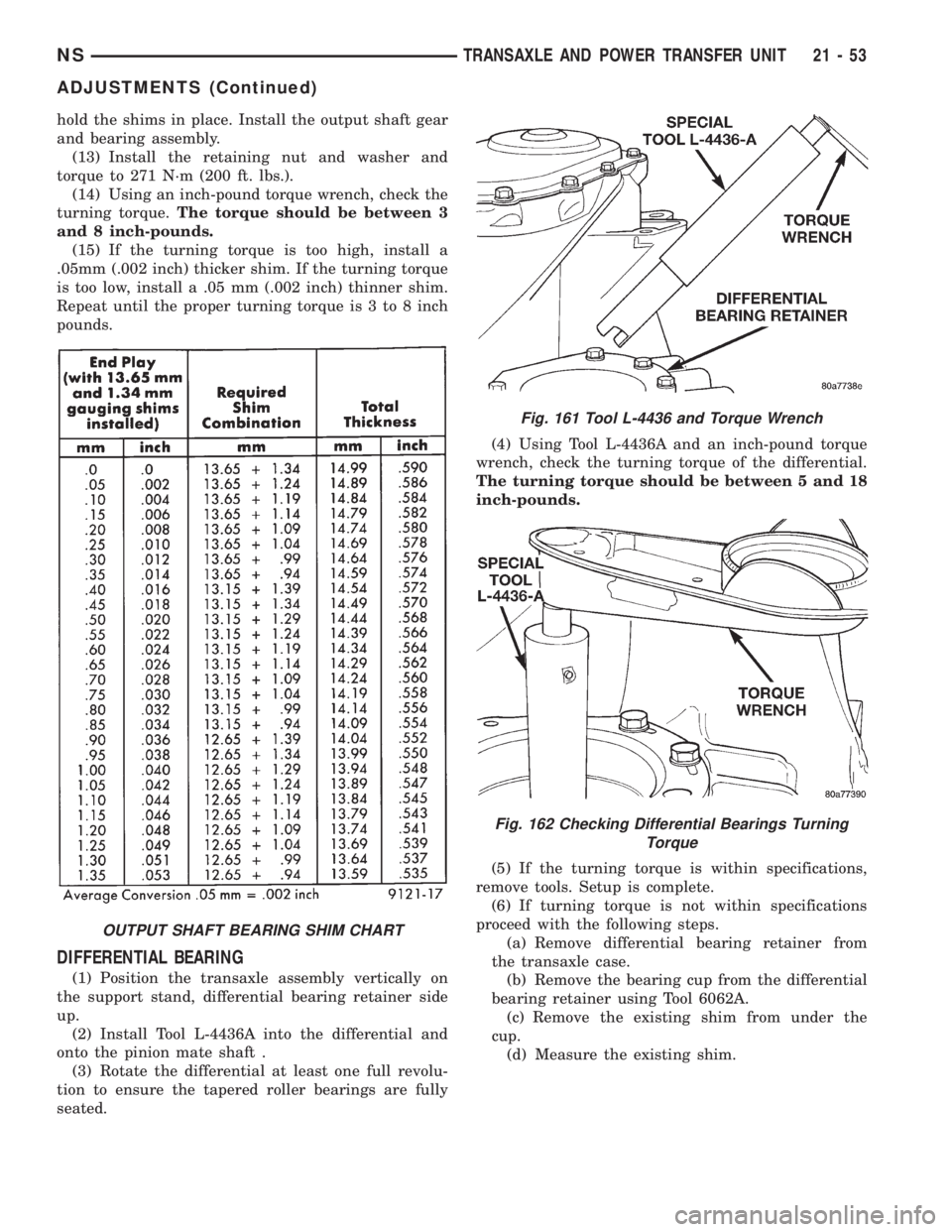
to bearing shim chart for proper shim thicknesses.
OUTPUT SHAFT BEARING
(1) With output shaft gear removed, install a 13.65
mm (.537 inch) and a 1.34 mm (.053 inch) gauging
shims on the planetary rear annulus gear hub using
grease to hold the shims in place. The 13.65 mm
shim has a larger inside diameter and must be
installed over the output shaft first. The 1.34 mm
shim pilots on the output shaft.
(2) Install output shaft gear and bearing assembly,
torque to 271 N´m (200 ft. lbs.).
(3) To measure bearing end play:
(4) Attach Tool L-4432 to the output shaft gear.
(5) Mount a steel ball with grease into the end of
the output shaft.
(6) Push and pull the gear while rotating back and
forth to insure seating of the bearing rollers.
(7) Using a dial indicator, mounted to the tran-
saxle case, measure output shaft end play.
(8) Once bearing end play has been determined,
refer to the output shaft bearing shim chart.
(9) The 12.65 mm (.498 inch), 13.15 mm (.518
inch) or 13.65 mm (.537 inch) shims are always
installed first.These shims have lubrication slots
which are necessary for proper bearing lubrica-
tion.
(10) Shims thinner than 12.65 mm listed in the
chart are common to both the transfer shaft and out-
put shaft bearings.
(11) Use Tool L-4434 to remove the retaining nut
and washer. To remove the output shaft gear use Tool
L-4407.
(12) Remove the two gauging shims and install the
proper shim combination, making sure to install the
12.65, 13.15, or 13.65 mm shim first. Use grease to
21 - 52 TRANSAXLE AND POWER TRANSFER UNITNS
ADJUSTMENTS (Continued)
Page 1527 of 1938
hold the shims in place. Install the output shaft gear
and bearing assembly.
(13) Install the retaining nut and washer and
torque to 271 N´m (200 ft. lbs.).
(14) Using an inch-pound torque wrench, check the
turning torque.The torque should be between 3
and 8 inch-pounds.
(15) If the turning torque is too high, install a
.05mm (.002 inch) thicker shim. If the turning torque
is too low, install a .05 mm (.002 inch) thinner shim.
Repeat until the proper turning torque is 3 to 8 inch
pounds.
DIFFERENTIAL BEARING
(1) Position the transaxle assembly vertically on
the support stand, differential bearing retainer side
up.
(2) Install Tool L-4436A into the differential and
onto the pinion mate shaft .
(3) Rotate the differential at least one full revolu-
tion to ensure the tapered roller bearings are fully
seated.(4) Using Tool L-4436A and an inch-pound torque
wrench, check the turning torque of the differential.
The turning torque should be between 5 and 18
inch-pounds.
(5) If the turning torque is within specifications,
remove tools. Setup is complete.
(6) If turning torque is not within specifications
proceed with the following steps.
(a) Remove differential bearing retainer from
the transaxle case.
(b) Remove the bearing cup from the differential
bearing retainer using Tool 6062A.
(c) Remove the existing shim from under the
cup.
(d) Measure the existing shim.
OUTPUT SHAFT BEARING SHIM CHART
Fig. 161 Tool L-4436 and Torque Wrench
Fig. 162 Checking Differential Bearings Turning
Torque
NSTRANSAXLE AND POWER TRANSFER UNIT 21 - 53
ADJUSTMENTS (Continued)
Page 1528 of 1938
NOTE: If the turning torque was too high when
measured, install a .05 mm (.002 inch) thinner shim.
If the turning torque is was too low, install a .05 mm
(.002 inch) thicker shim. Repeat until 5 to 18 inch-
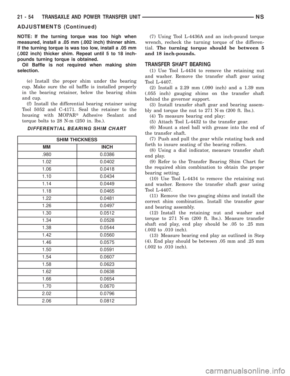
pounds turning torque is obtained.
Oil Baffle is not required when making shim
selection.
(e) Install the proper shim under the bearing
cup. Make sure the oil baffle is installed properly
in the bearing retainer, below the bearing shim
and cup.
(f) Install the differential bearing retainer using
Tool 5052 and C-4171. Seal the retainer to the
housing with MOPARtAdhesive Sealant and
torque bolts to 28 N´m (250 in. lbs.).(7) Using Tool L-4436A and an inch-pound torque
wrench, recheck the turning torque of the differen-
tial.The turning torque should be between 5
and 18 inch-pounds.
TRANSFER SHAFT BEARING
(1) Use Tool L-4434 to remove the retaining nut
and washer. Remove the transfer shaft gear using
Tool L-4407.
(2) Install a 2.29 mm (.090 inch) and a 1.39 mm
(.055 inch) gauging shims on the transfer shaft
behind the governor support.
(3) Install transfer shaft gear and bearing assem-
bly and torque the nut to 271 N´m (200 ft. lbs.).
(4) To measure bearing end play:
(5) Attach Tool L-4432 to the transfer gear.
(6) Mount a steel ball with grease into the end of
the transfer shaft.
(7) Push and pull the gear while rotating back and
forth to insure seating of the bearing rollers.
(8) Using a dial indicator, measure transfer shaft
end play.
(9) Refer to the Transfer Bearing Shim Chart for
the required shim combination to obtain the proper
bearing setting.
(10) Use Tool L-4434 to remove the retaining nut
and washer. Remove the transfer shaft gear using
Tool L-4407.
(11) Remove the two gauging shims and install the
correct shim combination. Install the transfer gear
and bearing assembly.
(12) Install the retaining nut and washer and
torque to 271 N´m (200 ft. lbs.). Measure transfer
shaft end play, end play should be .05 to .25 mm
(.002 to .010 inch).
(13) Measure bearing end play as outlined in Step
(4). End play should be between .05 mm and .25 mm
(.002 to .010 inch).
DIFFERENTIAL BEARING SHIM CHART
SHIM THICKNESS
MM INCH
.980 0.0386
1.02 0.0402
1.06 0.0418
1.10 0.0434
1.14 0.0449
1.18 0.0465
1.22 0.0481
1.26 0.0497
1.30 0.0512
1.34 0.0528
1.38 0.0544
1.42 0.0560
1.46 0.0575
1.50 0.0591
1.54 0.0607
1.58 0.0623
1.62 0.0638
1.66 0.0654
1.70 0.0670
2.02 0.0796
2.06 0.0812
21 - 54 TRANSAXLE AND POWER TRANSFER UNITNS
ADJUSTMENTS (Continued)