1996 CHRYSLER VOYAGER fuel
[x] Cancel search: fuelPage 1364 of 1938
(5) When the sensor is removed, the exhaust man-
ifold threads must be cleaned with an 18 mm X 1.5 +
6E tap. If using original sensor, coat the threads with
Loctite 771-64 anti-seize compound or equivalent.
INSTALLATION
(1) Reverse removal procedure to install a new
sensor.
New sensors are packaged with compound on the
threads and no additional compound is required. The
sensor must be tightened to 27 N´m (20 ft. lbs.)
torque.
KNOCK SENSOR
For removal/installation procedures refer to Group
8D- Ignition System, Service Procedures.
AIR CLEANER ELEMENT
REMOVAL
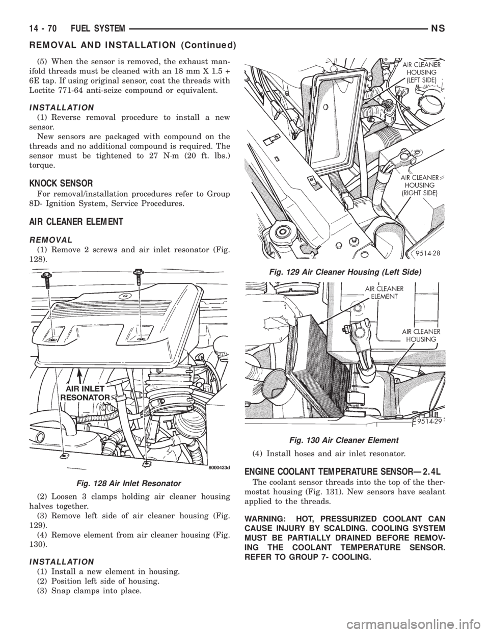
(1) Remove 2 screws and air inlet resonator (Fig.
128).
(2) Loosen 3 clamps holding air cleaner housing
halves together.
(3) Remove left side of air cleaner housing (Fig.
129).
(4) Remove element from air cleaner housing (Fig.
130).
INSTALLATION
(1) Install a new element in housing.
(2) Position left side of housing.
(3) Snap clamps into place.(4) Install hoses and air inlet resonator.
ENGINE COOLANT TEMPERATURE SENSORÐ2.4L
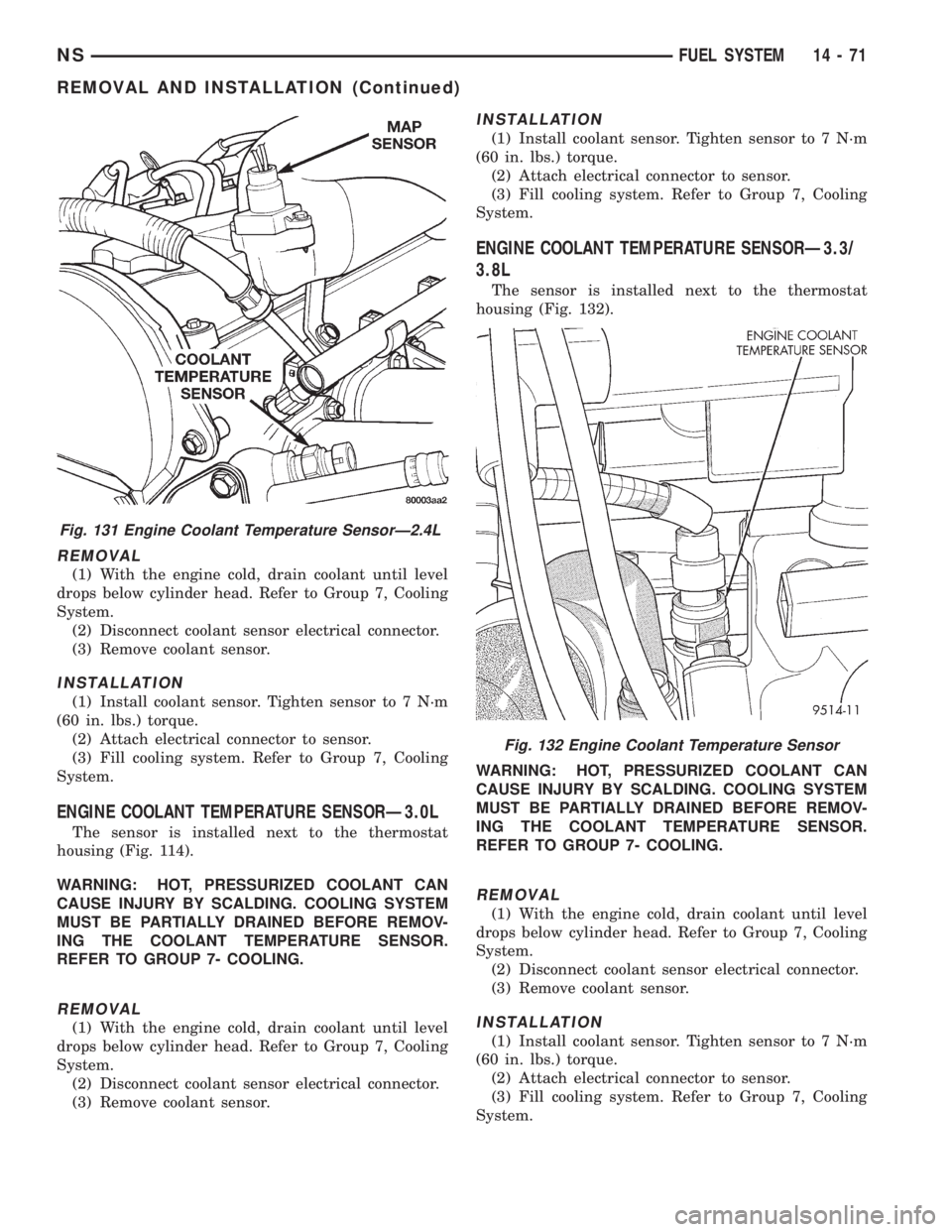
The coolant sensor threads into the top of the ther-
mostat housing (Fig. 131). New sensors have sealant
applied to the threads.
WARNING: HOT, PRESSURIZED COOLANT CAN
CAUSE INJURY BY SCALDING. COOLING SYSTEM
MUST BE PARTIALLY DRAINED BEFORE REMOV-
ING THE COOLANT TEMPERATURE SENSOR.
REFER TO GROUP 7- COOLING.Fig. 128 Air Inlet Resonator
Fig. 129 Air Cleaner Housing (Left Side)
Fig. 130 Air Cleaner Element
14 - 70 FUEL SYSTEMNS
REMOVAL AND INSTALLATION (Continued)
Page 1365 of 1938
REMOVAL
(1) With the engine cold, drain coolant until level
drops below cylinder head. Refer to Group 7, Cooling
System.
(2) Disconnect coolant sensor electrical connector.
(3) Remove coolant sensor.
INSTALLATION
(1) Install coolant sensor. Tighten sensor to 7 N´m
(60 in. lbs.) torque.
(2) Attach electrical connector to sensor.
(3) Fill cooling system. Refer to Group 7, Cooling
System.
ENGINE COOLANT TEMPERATURE SENSORÐ3.0L
The sensor is installed next to the thermostat
housing (Fig. 114).
WARNING: HOT, PRESSURIZED COOLANT CAN
CAUSE INJURY BY SCALDING. COOLING SYSTEM
MUST BE PARTIALLY DRAINED BEFORE REMOV-
ING THE COOLANT TEMPERATURE SENSOR.
REFER TO GROUP 7- COOLING.
REMOVAL
(1) With the engine cold, drain coolant until level
drops below cylinder head. Refer to Group 7, Cooling
System.
(2) Disconnect coolant sensor electrical connector.
(3) Remove coolant sensor.
INSTALLATION
(1) Install coolant sensor. Tighten sensor to 7 N´m
(60 in. lbs.) torque.
(2) Attach electrical connector to sensor.
(3) Fill cooling system. Refer to Group 7, Cooling
System.
ENGINE COOLANT TEMPERATURE SENSORÐ3.3/
3.8L
The sensor is installed next to the thermostat
housing (Fig. 132).
WARNING: HOT, PRESSURIZED COOLANT CAN
CAUSE INJURY BY SCALDING. COOLING SYSTEM
MUST BE PARTIALLY DRAINED BEFORE REMOV-
ING THE COOLANT TEMPERATURE SENSOR.
REFER TO GROUP 7- COOLING.
REMOVAL
(1) With the engine cold, drain coolant until level
drops below cylinder head. Refer to Group 7, Cooling
System.
(2) Disconnect coolant sensor electrical connector.
(3) Remove coolant sensor.
INSTALLATION
(1) Install coolant sensor. Tighten sensor to 7 N´m
(60 in. lbs.) torque.
(2) Attach electrical connector to sensor.
(3) Fill cooling system. Refer to Group 7, Cooling
System.
Fig. 131 Engine Coolant Temperature SensorÐ2.4L
Fig. 132 Engine Coolant Temperature Sensor
NSFUEL SYSTEM 14 - 71
REMOVAL AND INSTALLATION (Continued)
Page 1366 of 1938
INTAKE AIR TEMPERATURE SENSORÐ2.4L
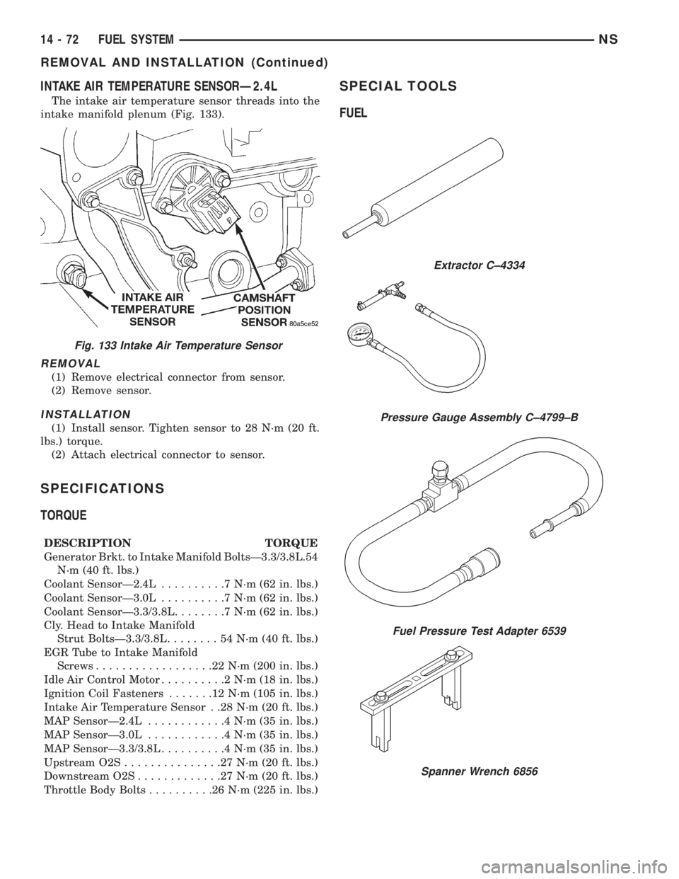
The intake air temperature sensor threads into the
intake manifold plenum (Fig. 133).
REMOVAL
(1) Remove electrical connector from sensor.
(2) Remove sensor.
INSTALLATION
(1) Install sensor. Tighten sensor to 28 N´m (20 ft.
lbs.) torque.
(2) Attach electrical connector to sensor.
SPECIFICATIONS
TORQUE
DESCRIPTION TORQUE
Generator Brkt. to Intake Manifold BoltsÐ3.3/3.8L.54
N´m (40 ft. lbs.)
Coolant SensorÐ2.4L..........7N´m(62in.lbs.)
Coolant SensorÐ3.0L..........7N´m(62in.lbs.)
Coolant SensorÐ3.3/3.8L........7N´m(62in.lbs.)
Cly. Head to Intake Manifold
Strut BoltsÐ3.3/3.8L........54N´m(40ft.lbs.)
EGR Tube to Intake Manifold
Screws..................22N´m(200 in. lbs.)
Idle Air Control Motor..........2N´m(18in.lbs.)
Ignition Coil Fasteners.......12N´m(105 in. lbs.)
Intake Air Temperature Sensor . .28 N´m (20 ft. lbs.)
MAP SensorÐ2.4L............4N´m(35in.lbs.)
MAP SensorÐ3.0L............4N´m(35in.lbs.)
MAP SensorÐ3.3/3.8L..........4N´m(35in.lbs.)
Upstream O2S...............27N´m(20ft.lbs.)
Downstream O2S.............27N´m(20ft.lbs.)
Throttle Body Bolts..........26N´m(225 in. lbs.)
SPECIAL TOOLS
FUEL
Fig. 133 Intake Air Temperature Sensor
Extractor C±4334
Pressure Gauge Assembly C±4799±B
Fuel Pressure Test Adapter 6539
Spanner Wrench 6856
14 - 72 FUEL SYSTEMNS
REMOVAL AND INSTALLATION (Continued)
Page 1367 of 1938
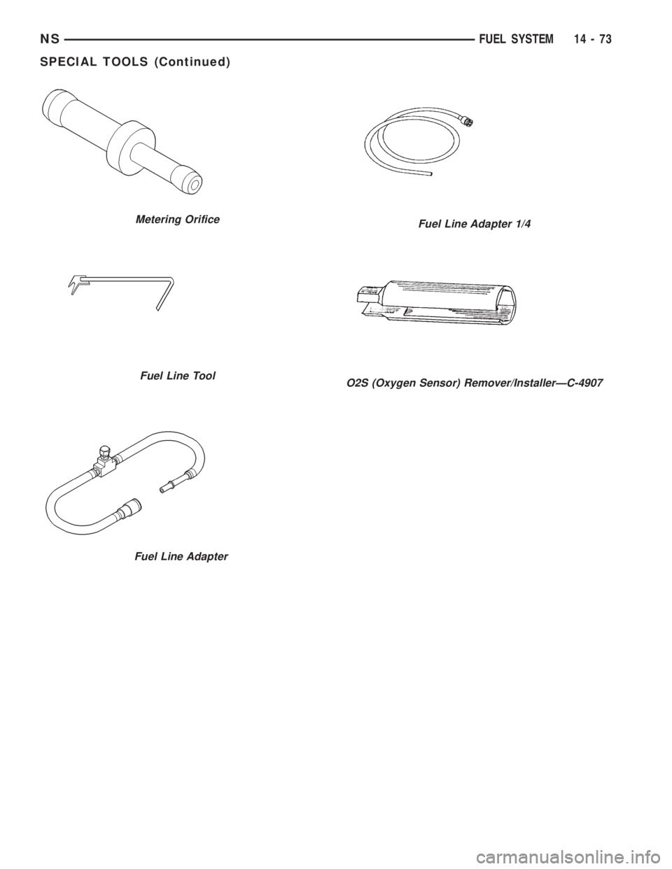
Metering Orifice
Fuel Line Tool
Fuel Line Adapter
Fuel Line Adapter 1/4
O2S (Oxygen Sensor) Remover/InstallerÐC-4907
NSFUEL SYSTEM 14 - 73
SPECIAL TOOLS (Continued)
Page 1369 of 1938
FUEL SYSTEMÐ2.5L DIESEL ENGINE/2.0L GAS ENGINE
CONTENTS
page page
FUEL DELIVERY SYSTEMÐ2.0L ENGINE.... 28
FUEL DELIVERY SYSTEMÐ2.5L DIESEL
ENGINE.............................. 3
FUEL INJECTION SYSTEMÐ2.0L ENGINE . . . 32FUEL INJECTION SYSTEMÐ2.5L DIESEL
ENGINE............................. 43
GENERAL INFORMATION.................. 1
GENERAL INFORMATION
INDEX
page page
GENERAL INFORMATION
FUEL REQUIREMENTSÐ2.0L ENGINE....... 2
FUEL REQUIREMENTSÐ2.5L DIESEL........ 2GASOLINE/OXYGENATE BLENDS........... 2
INTRODUCTIONÐ2.0L ENGINE............. 2
INTRODUCTIONÐ2.5L DIESEL............. 1
GENERAL INFORMATION
INTRODUCTIONÐ2.5L DIESEL
Certain components of the fuel system on the 2.5L
diesel engine are controlled by the Bosch Engine con-
troller which is a Powertrain Control Module (PCM).
Refer to Powertrain Control Module in the Fuel
Injection SystemÐ2.5L Diesel Engine section of this
group for a list of items controlled by the PCM. The
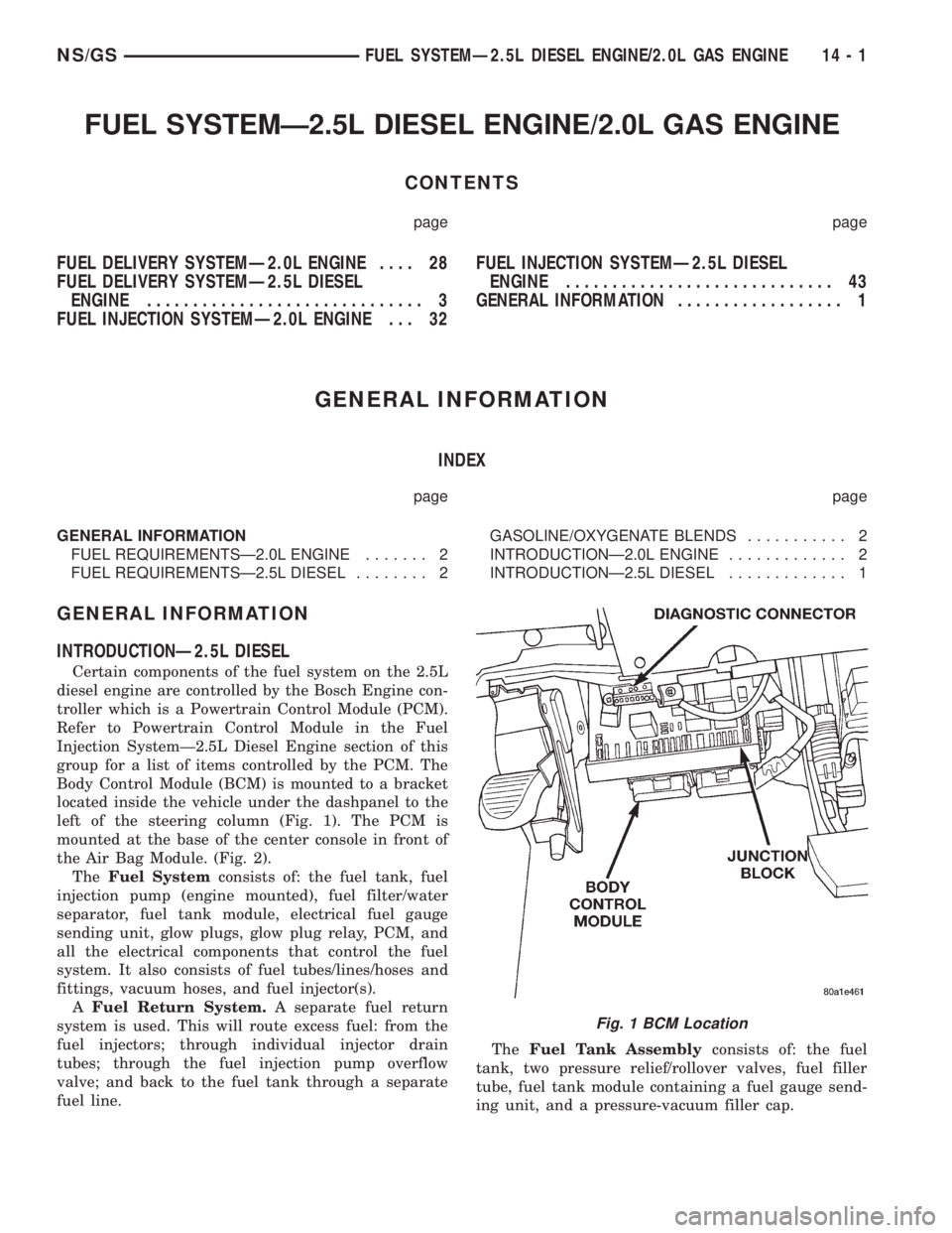
Body Control Module (BCM) is mounted to a bracket
located inside the vehicle under the dashpanel to the
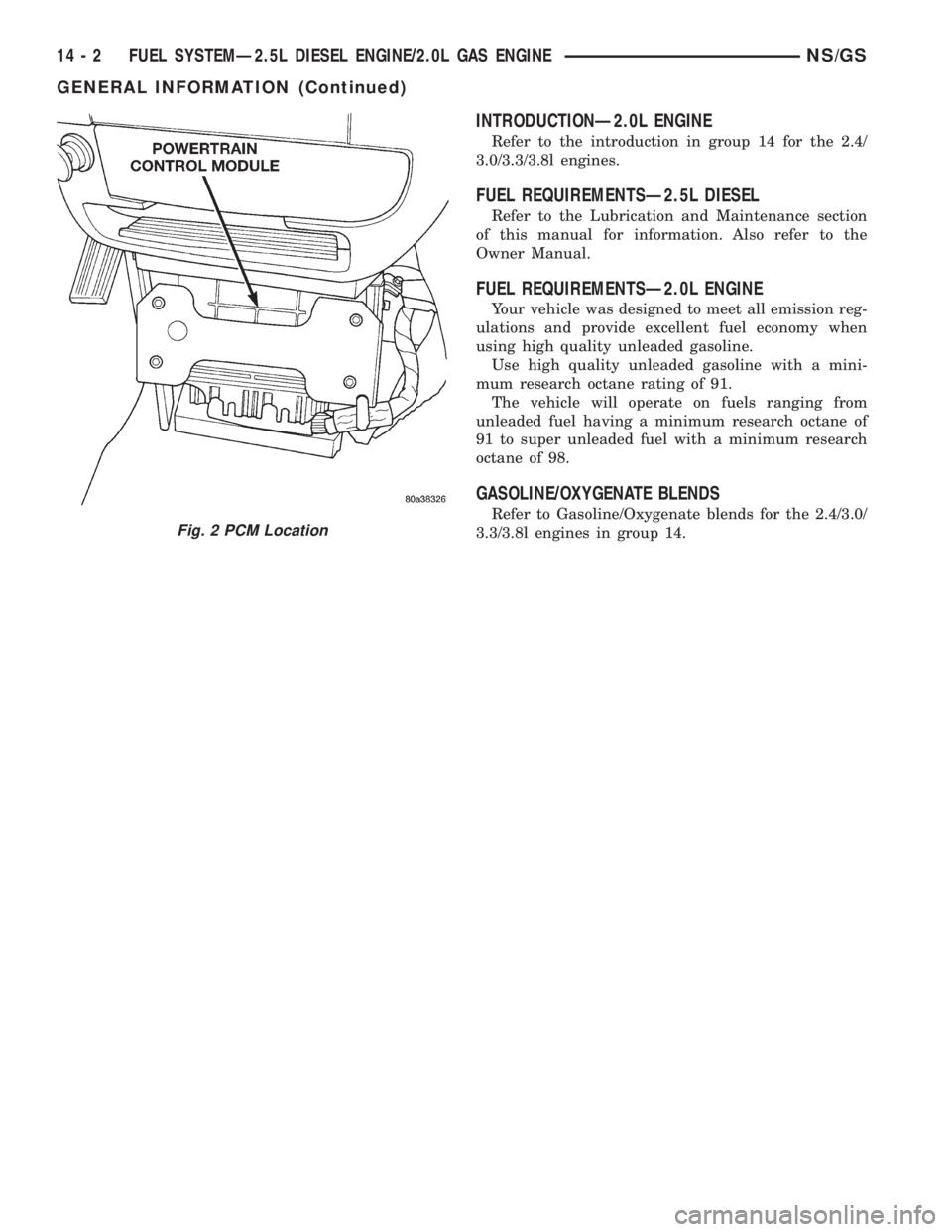
left of the steering column (Fig. 1). The PCM is
mounted at the base of the center console in front of
the Air Bag Module. (Fig. 2).
TheFuel Systemconsists of: the fuel tank, fuel
injection pump (engine mounted), fuel filter/water
separator, fuel tank module, electrical fuel gauge
sending unit, glow plugs, glow plug relay, PCM, and
all the electrical components that control the fuel
system. It also consists of fuel tubes/lines/hoses and
fittings, vacuum hoses, and fuel injector(s).
AFuel Return System.A separate fuel return
system is used. This will route excess fuel: from the
fuel injectors; through individual injector drain
tubes; through the fuel injection pump overflow
valve; and back to the fuel tank through a separate
fuel line.TheFuel Tank Assemblyconsists of: the fuel
tank, two pressure relief/rollover valves, fuel filler
tube, fuel tank module containing a fuel gauge send-
ing unit, and a pressure-vacuum filler cap.
Fig. 1 BCM Location
NS/GSFUEL SYSTEMÐ2.5L DIESEL ENGINE/2.0L GAS ENGINE 14 - 1
Page 1370 of 1938
INTRODUCTIONÐ2.0L ENGINE
Refer to the introduction in group 14 for the 2.4/
3.0/3.3/3.8l engines.
FUEL REQUIREMENTSÐ2.5L DIESEL
Refer to the Lubrication and Maintenance section
of this manual for information. Also refer to the
Owner Manual.
FUEL REQUIREMENTSÐ2.0L ENGINE
Your vehicle was designed to meet all emission reg-
ulations and provide excellent fuel economy when
using high quality unleaded gasoline.
Use high quality unleaded gasoline with a mini-
mum research octane rating of 91.
The vehicle will operate on fuels ranging from
unleaded fuel having a minimum research octane of
91 to super unleaded fuel with a minimum research
octane of 98.
GASOLINE/OXYGENATE BLENDS
Refer to Gasoline/Oxygenate blends for the 2.4/3.0/
3.3/3.8l engines in group 14.
Fig. 2 PCM Location
14 - 2 FUEL SYSTEMÐ2.5L DIESEL ENGINE/2.0L GAS ENGINENS/GS
GENERAL INFORMATION (Continued)
Page 1371 of 1938
FUEL DELIVERY SYSTEMÐ2.5L DIESEL ENGINE
INDEX
page page
DESCRIPTION AND OPERATION
FUEL DRAIN TUBES..................... 7
FUEL FILTER/WATER SEPARATOR.......... 4
FUEL GAUGE SENDING UNIT.............. 4
FUEL HEATER RELAY.................... 8
FUEL HEATER.......................... 8
FUEL INJECTION PUMP.................. 5
FUEL INJECTORS....................... 6
FUEL SHUTDOWN SOLENOID............. 5
FUEL SYSTEM PRESSURE WARNING....... 3
FUEL TANK MODULE.................... 4
FUEL TANK............................ 3
FUEL TUBES/LINES/HOSES AND CLAMPSÐ
LOW-PRESSURE TYPE................. 6
HIGH-PRESSURE FUEL LINES............. 7
INTRODUCTION........................ 3
QUICK-CONNECT FITTINGSÐLOW PRESSURE
TYPE............................... 7
WASTEGATE (TURBOCHARGER)........... 8
DIAGNOSIS AND TESTING
AIR IN FUEL SYSTEM................... 11
FUEL HEATER RELAY TEST.............. 12
FUEL INJECTION PUMP TEST............. 12
FUEL INJECTOR SENSOR TEST........... 12
FUEL INJECTOR TEST.................. 12
FUEL SHUTDOWN SOLENOID TEST........ 13
FUEL SUPPLY RESTRICTIONS............ 13GENERAL INFORMATION................. 9
HIGH-PRESSURE FUEL LINE LEAK TEST.... 14
VISUAL INSPECTION..................... 9
WASTEGATE (TURBOCHARGER).......... 14
SERVICE PROCEDURES
AIR BLEED PROCEDURES............... 14
FUEL INJECTION PUMP TIMING........... 15
REMOVAL AND INSTALLATION
ACCELERATOR PEDAL.................. 16
AIR CLEANER ELEMENT................. 16
FUEL DRAIN TUBES.................... 16
FUEL FILTER/WATER SEPARATOR......... 16
FUEL HEATER RELAY................... 17
FUEL HEATER......................... 17
FUEL INJECTION PUMP................. 19
FUEL INJECTORS...................... 22
FUEL LEVEL SENSOR................... 18
FUEL RESERVOIR MODULE.............. 25
FUEL SHUTDOWN SOLENOID............ 23
FUEL TANK........................... 23
HIGH-PRESSURE LINES................. 26
SPECIFICATIONS
FUEL INJECTOR FIRING SEQUENCE....... 27
FUEL SYSTEM PRESSURE............... 27
FUEL TANK CAPACITY.................. 27
IDLE SPEED.......................... 27
DESCRIPTION AND OPERATION
INTRODUCTION
This Fuel Delivery section will cover components
not controlled by the PCM. For components con-
trolled by the PCM, refer to the Fuel Injection Sys-
temÐ2.5L Diesel Engine section of this group.
The fuel heater relay, fuel heater and fuel gauge
are not operated by the PCM. These components are
controlled by the ignition (key) switch. All other fuel
system electrical components necessary to operate
the engine are controlled or regulated by the PCM.
FUEL SYSTEM PRESSURE WARNING
WARNING: HIGH±PRESSURE FUEL LINES DELIVER
DIESEL FUEL UNDER EXTREME PRESSURE FROM
THE INJECTION PUMP TO THE FUEL INJECTORS.
THIS MAY BE AS HIGH AS 45,000 KPA (6526 PSI).
USE EXTREME CAUTION WHEN INSPECTING FORHIGH±PRESSURE FUEL LEAKS. INSPECT FOR
HIGH±PRESSURE FUEL LEAKS WITH A SHEET OF
CARDBOARD (Fig. 1). HIGH FUEL INJECTION
PRESSURE CAN CAUSE PERSONAL INJURY IF
CONTACT IS MADE WITH THE SKIN.
FUEL TANK
The fuel tank and tank mounting used with the
diesel powered engine is the same as used with gas-
oline powered models, although the fuel tank module
is different.
The fuel tank contains the fuel tank module and
two rollover valves. Two fuel lines are routed to the
fuel tank module. One line is used for fuel supply to
the fuel filter/water separator. The other is used to
return excess fuel back to the fuel tank.
The fuel tank module contains the fuel gauge elec-
trical sending unit.An electrical fuel pump is not
used with the diesel engine.
NS/GSFUEL SYSTEMÐ2.5L DIESEL ENGINE/2.0L GAS ENGINE 14 - 3
Page 1372 of 1938
FUEL TANK MODULE
An electric fuel pump is not attached to the fuel
tank module for diesel powered engines. Fuel is sup-
plied by the fuel injection pump.
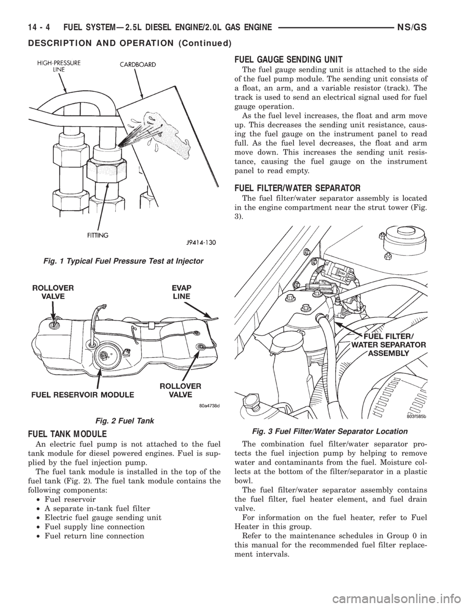
The fuel tank module is installed in the top of the
fuel tank (Fig. 2). The fuel tank module contains the
following components:
²Fuel reservoir
²A separate in-tank fuel filter
²Electric fuel gauge sending unit
²Fuel supply line connection
²Fuel return line connection
FUEL GAUGE SENDING UNIT
The fuel gauge sending unit is attached to the side
of the fuel pump module. The sending unit consists of
a float, an arm, and a variable resistor (track). The
track is used to send an electrical signal used for fuel
gauge operation.
As the fuel level increases, the float and arm move
up. This decreases the sending unit resistance, caus-
ing the fuel gauge on the instrument panel to read
full. As the fuel level decreases, the float and arm
move down. This increases the sending unit resis-
tance, causing the fuel gauge on the instrument
panel to read empty.
FUEL FILTER/WATER SEPARATOR
The fuel filter/water separator assembly is located
in the engine compartment near the strut tower (Fig.
3).
The combination fuel filter/water separator pro-
tects the fuel injection pump by helping to remove
water and contaminants from the fuel. Moisture col-
lects at the bottom of the filter/separator in a plastic
bowl.
The fuel filter/water separator assembly contains
the fuel filter, fuel heater element, and fuel drain
valve.
For information on the fuel heater, refer to Fuel
Heater in this group.
Refer to the maintenance schedules in Group 0 in
this manual for the recommended fuel filter replace-
ment intervals.
Fig. 1 Typical Fuel Pressure Test at Injector
Fig. 2 Fuel Tank
Fig. 3 Fuel Filter/Water Separator Location
14 - 4 FUEL SYSTEMÐ2.5L DIESEL ENGINE/2.0L GAS ENGINENS/GS
DESCRIPTION AND OPERATION (Continued)