Page 1340 of 1938
Shutdown (ASD) RelayÐPCM Output in this section
for relay operation.
TORQUE CONVERTER CLUTCH SOLENOIDÐPCM
OUTPUT
Three-speed automatic transaxles use a torque con-
verter clutch solenoid. The PCM controls the engage-
ment of the torque converter clutch through the
solenoid. The torque converter clutch is engaged only
in direct drive mode. Refer to Group 21 for transaxle
information.
MALFUNCTION INDICATOR (CHECK ENGINE)
LAMPÐPCM OUTPUT
The PCM supplies the malfunction indicator (check
engine) lamp on/off signal to the instrument panel
through the CCD Bus. The CCD Bus is a communi-
cations port. Various modules use the CCD Bus to
exchange information.
The Check Engine lamp comes on each time the
ignition key is turned ON and stays on for 3 seconds
as a bulb test.
The Malfunction Indicator Lamp (MIL) stays on
continuously, when the PCM has entered a Limp-In
mode or identified a failed emission component. Dur-
ing Limp-in Mode, the PCM attempts to keep the
system operational. The MIL signals the need for
immediate service. In limp-in mode, the PCM com-
pensates for the failure of certain components that
send incorrect signals. The PCM substitutes for the
incorrect signals with inputs from other sensors.
If the PCM detects active engine misfire severe
enough to cause catalyst damage, it flashes the MIL.
At the same time the PCM also sets a Diagnostic
Trouble Code (DTC).
For signals that can trigger the MIL (Check
Engine Lamp) refer to Group 25, On-Board
Dianostics.
SOLID STATE FAN RELAYÐPCM OUTPUT
The radiator fan runs at a variable speed depend-
ing on coolant temperature and A/C system pressure.
The radiator fan circuit contains a Solid State Fan
Relay (SSFR). Refer to the Group 8W for a circuit
schematic.
A 5 volt signal is supplied to the SSFR. The PCM
provides a pulsed ground for the SSFR. Depending
upon the amount of pulse on time, the SSFR puts out
a proportional voltage to the fan motor at the lower
speed. For instance, if the on time is 30 percent, then
the voltage to the fan motor will be 3.6 volts.
When engine coolant reaches approximately 102ÉC
(215ÉF) the PCM grounds the SSFR relay. If engine
coolant reaches 207ÉC (225ÉF) the PCM grounds the
high speed ground relay and high speed fan relay. If
the fan operates at high speed, the PCM de-energizes
the high speed relay and high speed ground relay
when coolant temperature drops to approximately
101ÉC (214ÉF). When coolant temperature drops to
101ÉC (214ÉF) the fan operates at low speed. The
PCM de-energizes the low speed relay when coolant
temperature drops to approximately 93ÉC (199ÉF).
Also, when the air conditioning pressure switch
closes, the fan operates at high speed. The air condi-
tioning switch closes at 285 psi610 psi. When air
conditioning pressure drops approximately 40 psi, the
pressure switch opens and the fan operates at low
speed.
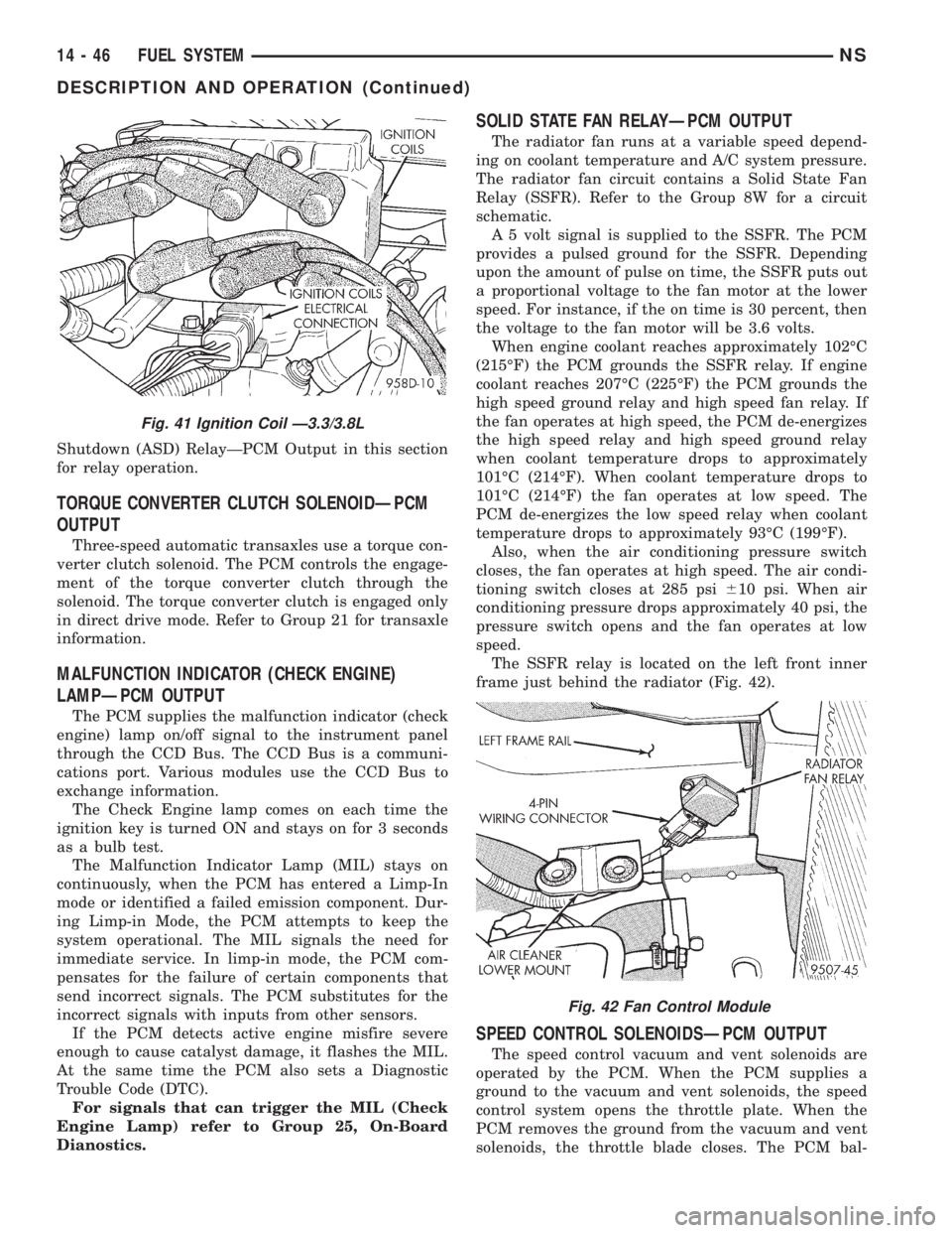
The SSFR relay is located on the left front inner
frame just behind the radiator (Fig. 42).
SPEED CONTROL SOLENOIDSÐPCM OUTPUT
The speed control vacuum and vent solenoids are
operated by the PCM. When the PCM supplies a
ground to the vacuum and vent solenoids, the speed
control system opens the throttle plate. When the
PCM removes the ground from the vacuum and vent
solenoids, the throttle blade closes. The PCM bal-
Fig. 41 Ignition Coil Ð3.3/3.8L
Fig. 42 Fan Control Module
14 - 46 FUEL SYSTEMNS
DESCRIPTION AND OPERATION (Continued)
Page 1341 of 1938
ances the two solenoids to maintain the set speed.
Refer to Group 8H for speed control information.
TACHOMETERÐPCM OUTPUT
The PCM supplies engine RPM to the instrument
panel tachometer through the CCD Bus. The CCD
Bus is a communications port. Various modules use
the CCD Bus to exchange information. Refer to
Group 8E for more information.
THROTTLE BODY
On all engine assemblies (2.4, 3.0, and 3.3/3.8L)
the throttle body's are located on the left side of the
intake manifold plenum. The throttle body houses
the throttle position sensor and the idle air control
motor. Air flow through the throttle body is con-
trolled by a cable operated throttle blade located in
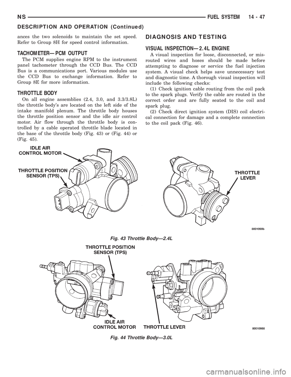
the base of the throttle body (Fig. 43) or (Fig. 44) or
(Fig. 45).
DIAGNOSIS AND TESTING
VISUAL INSPECTIONÐ2.4L ENGINE
A visual inspection for loose, disconnected, or mis-
routed wires and hoses should be made before
attempting to diagnose or service the fuel injection
system. A visual check helps save unnecessary test
and diagnostic time. A thorough visual inspection will
include the following checks:
(1) Check ignition cable routing from the coil pack
to the spark plugs. Verify the cable are routed in the
correct order and are fully seated to the coil and
spark plug.
(2) Check direct ignition system (DIS) coil electri-
cal connection for damage and a complete connection
to the coil pack (Fig. 46).
Fig. 43 Throttle BodyÐ2.4L
Fig. 44 Throttle BodyÐ3.0L
NSFUEL SYSTEM 14 - 47
DESCRIPTION AND OPERATION (Continued)
Page 1342 of 1938
(3) Verify the camshaft position sensor electrical
connector is connected to the harness and not dam-
aged (Fig. 47).(4) Ensure the engine temperature sensor electri-
cal connector is connected to the sensor and not dam-
aged (Fig. 48).
(5) Verify the quick connect fuel fitting is fully
inserted on the fuel supply tube.
(6) Check the oil pressure sending unit electrical
connection.
(7) Verify the electrical connector at the knock sen-
sor is fully seated and not damaged (Fig. 49).
Fig. 45 Throttle BodyÐ3.3/3.8L
Fig. 46 Ignition Coil Pack Electrical Connection
Fig. 47 Camshaft Position Sensor
14 - 48 FUEL SYSTEMNS
DIAGNOSIS AND TESTING (Continued)
Page 1343 of 1938
(8) Verify the electrical connector is attached to
the Proportional purge solenoid (Fig. 50) and not
damaged.
(9) Verify the vacuum connection at the Propor-
tional purge solenoid is secure and not leaking.
(10) Verify the hoses are securely attached to the
EVAP canister (Fig. 51).(11) Ensure the harness connectors for the fuel
injectors are attached to the correct injector and not
damaged.
(12) Verify the fuel injector harness and engine
wiring harness connectors are fully inserted into the
main wiring harness.
(13) Check the vacuum connections at the throttle
body and intake plenum.
Fig. 48 Engine Coolant Temperature Sensor
Fig. 49 Knock Sensor
Fig. 50 Proportional Purge Solenoid
Fig. 51 Evaporative Canister
NSFUEL SYSTEM 14 - 49
DIAGNOSIS AND TESTING (Continued)
Page 1344 of 1938
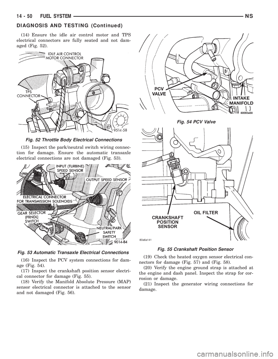
(14) Ensure the idle air control motor and TPS
electrical connectors are fully seated and not dam-
aged (Fig. 52).
(15) Inspect the park/neutral switch wiring connec-
tion for damage. Ensure the automatic transaxle
electrical connections are not damaged (Fig. 53).
(16) Inspect the PCV system connections for dam-
age (Fig. 54).
(17) Inspect the crankshaft position sensor electri-
cal connector for damage (Fig. 55).
(18) Verify the Manifold Absolute Pressure (MAP)
sensor electrical connector is attached to the sensor
and not damaged (Fig. 56).(19) Check the heated oxygen sensor electrical con-
nectors for damage (Fig. 57) and (Fig. 58).
(20) Verify the engine ground strap is attached at
the engine and dash panel. Inspect the strap for cor-
rosion or damage.
(21) Inspect the generator wiring connections for
damage.
Fig. 52 Throttle Body Electrical Connections
Fig. 53 Automatic Transaxle Electrical Connections
Fig. 54 PCV Valve
Fig. 55 Crankshaft Position Sensor
14 - 50 FUEL SYSTEMNS
DIAGNOSIS AND TESTING (Continued)
Page 1345 of 1938
(22) Check the accessory drive belt tension.
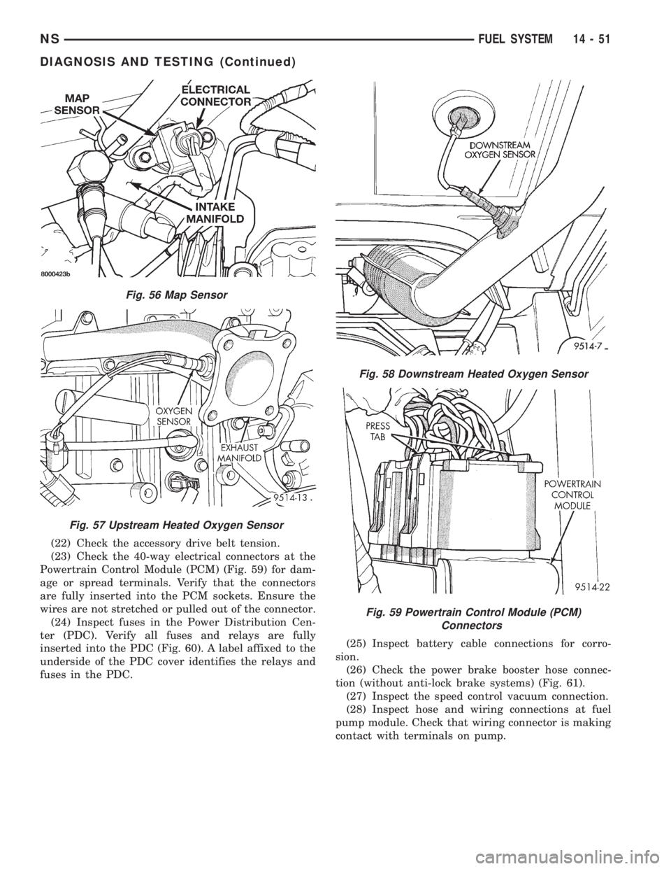
(23) Check the 40-way electrical connectors at the
Powertrain Control Module (PCM) (Fig. 59) for dam-
age or spread terminals. Verify that the connectors
are fully inserted into the PCM sockets. Ensure the
wires are not stretched or pulled out of the connector.
(24) Inspect fuses in the Power Distribution Cen-
ter (PDC). Verify all fuses and relays are fully
inserted into the PDC (Fig. 60). A label affixed to the
underside of the PDC cover identifies the relays and
fuses in the PDC.(25) Inspect battery cable connections for corro-
sion.
(26) Check the power brake booster hose connec-
tion (without anti-lock brake systems) (Fig. 61).
(27) Inspect the speed control vacuum connection.
(28) Inspect hose and wiring connections at fuel
pump module. Check that wiring connector is making
contact with terminals on pump.
Fig. 56 Map Sensor
Fig. 57 Upstream Heated Oxygen Sensor
Fig. 58 Downstream Heated Oxygen Sensor
Fig. 59 Powertrain Control Module (PCM)
Connectors
NSFUEL SYSTEM 14 - 51
DIAGNOSIS AND TESTING (Continued)
Page 1346 of 1938
VISUAL INSPECTIONÐ3.0L ENGINE
A visual inspection for loose, disconnected, or mis-
routed wires and hoses should be made before
attempting to diagnose or service the fuel injection
system. A visual check helps save unnecessary test
and diagnostic time. A thorough visual inspection will
include the following checks:(1) Check for correct spark plug cable routing.
Ensure that the cables are completely connected to
the spark plugs and distributor.
(2) Check ignition coil electrical connections (Fig.
62).
(3) Verify that the electrical connector is attached
to the Proportional Purge Solenoid (Fig. 63).
(4) Verify that vacuum connection at the duty cycle
Proportional Purge Solenoid valve is secure and not
leaking.
Fig. 60 Power Distribution Center (PDC)
Fig. 61 Power Brake Booster Hose
Fig. 62 Ignition Coil Electrical Connection
Fig. 63 Proportional Purge Solenoid Valve
14 - 52 FUEL SYSTEMNS
DIAGNOSIS AND TESTING (Continued)
Page 1347 of 1938
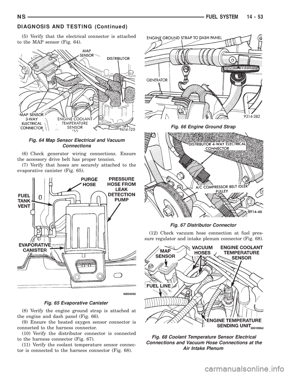
(5) Verify that the electrical connector is attached
to the MAP sensor (Fig. 64).
(6) Check generator wiring connections. Ensure
the accessory drive belt has proper tension.
(7) Verify that hoses are securely attached to the
evaporative canister (Fig. 65).
(8) Verify the engine ground strap is attached at
the engine and dash panel (Fig. 66).
(9) Ensure the heated oxygen sensor connector is
connected to the harness connector.
(10) Verify the distributor connector is connected
to the harness connector (Fig. 67).
(11) Verify the coolant temperature sensor connec-
tor is connected to the harness connector (Fig. 68).(12) Check vacuum hose connection at fuel pres-
sure regulator and intake plenum connector (Fig. 68).
Fig. 64 Map Sensor Electrical and Vacuum
Connections
Fig. 65 Evaporative Canister
Fig. 66 Engine Ground Strap
Fig. 67 Distributor Connector
Fig. 68 Coolant Temperature Sensor Electrical
Connections and Vacuum Hose Connections at the
Air Intake Plenum
NSFUEL SYSTEM 14 - 53
DIAGNOSIS AND TESTING (Continued)