1996 CHRYSLER VOYAGER tires
[x] Cancel search: tiresPage 418 of 1938

²Depressing the OFF switch
²Depressing the CANCEL switch.
NOTE: Depressing the OFF switch or turning off
the ignition switch will erase the set speed stored
in the PCM.
For added safety,the speed control system is pro-
grammed to disengaged for any of the following con-
ditions:
²An indication of Park or Neutral
²An rpm increase without a VSS signal increase
(indicates that the clutch has been disengaged)
²Excessive engine rpm (indicates that the trans-
mission may be in a low gear)
²The VSS signal increases at a rate of 10 mph
per second (indicates that the co-efficient of friction
between the road surface and tires is extremely low)
²The VSS signal decreases at a rate of 10 mph
per second (indicates that the vehicle may have
decelerated at an extremely high rate)
²If the actual speed is not within 20 mph of the
set speed
The previous disengagement conditions are pro-
grammed for added safety.
Once the speed control has been disengaged,
depressing the ACCEL switch when speed is greater
than 25 mph restores the vehicle to the target speed
that was stored in the PCM.
NOTE: Depressing the OFF switch will erase the
set speed stored in the PCM's RAM.
While the speed control is engaged, the driver can
increase the vehicle speed by depressing the ACCEL
switch. The new target speed is stored in the PCM
when the ACCEL is released. The PCM also has a
9tap-up9feature in which vehicle speed increases at a
rate of approximately 2 mph for each momentary
switch activation of the ACCEL switch. The PCM
also provides a means to decelerate without disen-
gaging speed control. To decelerate from an existing
recorded target speed, depress and hold the COAST
switch until the desired speed is reached, then
release the switch.
The individual switches cannot be repaired. If one
switch fails, the entire switch module must be
replaced.
AUTOMATIC SPEED CONTROL OVERSPEED
REDUCTION
Transmission control software includes an auto-
matic speed control overspeed reduction feature. This
maintains vehicle speed at the selected set point
when descending a grade.
The Transmission Control Module (TCM) first
senses that the speed control is set. If the set speedis exceeded by more than 4 mph (6.5 km/hr) and the
throttle is closed, the TCM causes the transaxle to
downshift to THIRD gear. After downshifting, the
automatic speed control resumes normal operation.
To ensure that an upshift is appropriate after the set
speed is reached, the TCM waits until the speed con-
trol system opens the throttle at least 8 degrees
before upshifting to OVERDRIVE again.
If the driver applies the brakes, canceling auto-
matic speed control operation with the transaxle still
in THIRD gear, the TCM maintains this gear until
the driver opens the throttle at least 8 degrees to
avoid an inappropriate upshift. The upshift is also
delayed for 0.5 seconds after reaching the 8 degrees
throttle opening in anticipation that the driver might
open the throttle enough to require THIRD gear.
This will avoid unnecessary and disturbing transmis-
sion cycling. If the automatic speed control RESUME
feature is used after braking, the upshift is delayed
until the set speed is achieved to reduce cycling and
provide better response.
STOP LAMP SWITCH
Vehicles equipped with the speed control option use
a dual function stop lamp switch. The switch is
mounted on the brake pedal mounting bracket under
the instrument panel. The PCM monitors the state of
the dual function stop lamp switch. Refer to Group 5,
Brakes for more information on stop lamp switch ser-
vice and adjustment procedures.
SERVO CABLE
The speed control servo cable is connected between
the speed control vacuum servo diaphragm and the
throttle body control linkage. This cable causes the
throttle control linkage to open or close the throttle
valve in response to movement of the vacuum servo
diaphragm.
POWERTRAIN CONTROL MODULE
The speed control electronic control circuitry is
integrated into the Powertrain Control Module
(PCM). The PCM is located in the engine compart-
ment. The PCM speed control functions are moni-
tored by the On-Board Diagnostics (OBD). All OBD-
sensed systems are monitored by the PCM. Each
monitored circuit is assigned a Diagnostic Trouble
Code (DTC). The PCM will store a DTC in electronic
memory for any failure it detects. See On-Board
Diagnostic Tests in this group for more information.
The PCM cannot be repaired and must be replaced if
faulty.
USE THE DRB SCAN TOOL TO REPROGRAM
THE NEW PCM WITH THE VEHICLES ORIGI-
NAL IDENTIFICATION NUMBER (VIN) AND
THE ORGINAL VEHICLES MILAGE. IF THIS
8H - 2 VEHICLE SPEED CONTROL SYSTEMNS
DESCRIPTION AND OPERATION (Continued)
Page 444 of 1938

MULTI-FUNCTION SWITCH
To test the windshield wiper and washer portion of
the multi-function switch:
(1) Remove the multi-function switch, refer to
removal procedures.
(2) Using an ohmmeter check continuity reading
between switch pins, refer to (Fig. 1) for proper pin
numbers.
REMOVAL AND INSTALLATION
MULTI-FUNCTION SWITCH
WARNING: BEFORE SERVICING A STEERING COL-
UMN EQUIPPED WITH AN AIRBAG REFER TO
GROUP 8M, RESTRAINT SYSTEMS FOR PROPER
AND SAFE SERVICE PROCEDURES.
REMOVAL
(1) Release hood latch and open hood.
(2) Disconnect and isolate battery negative cable.
(3) Remove upper and lower steering column
shrouds, refer to Group 19, Steering for proper pro-
cedures.
(4) Disconnect wire connector from back of turn
signal multi-function switch (Fig. 2).
(5) Remove screws holding turn signal switch to
steering column adapter collar.
(6) Remove turn signal switch.
INSTALLATION
For installation, reverse the above procedures. Ver-
ify switch operation by placing the control stalk ineither the right or left position and turning the steer-
ing wheel to ensure the automatic cancellation of the
switch.
WINDSHIELD WASHER BOTTLE
REMOVAL
(1) Hoist and support vehicle on safety stands.
(2) Remove right front wheel, refer to Group 22,
Wheels and Tires for proper procedures and tighten-
ing sequences.
(3) Remove front wheelhouse splash shield.
(4) Disconnect wire connectors from the windshield
and rear window washer pumps (Fig. 3).
(5) If washer bottle has fluid in it place a suitable
drain pan under the hose connections.
Fig. 1 Windshield Wiper and Washer±Multi-Function
Switch Test
Fig. 2 Turn Signal Multi-Function Switch
Fig. 3 Windshield Washer Bottle
8K - 4 WINDSHIELD WIPERS AND WASHERSNS
DIAGNOSIS AND TESTING (Continued)
Page 502 of 1938
DEPLOYED MODULE
The Driver Airbag Module and Driver Airbag Cov-
er/Horn Pad are serviced separately from eachother.
REMOVAL
(1) Disconnect battery negative cable. Allow at
least two minutes for the reserve capacitor in the
ACM to discharge.
(2) Clean powder residue from interior of vehicle,
refer to Cleanup Procedure.
(3) Remove three screws attaching Driver Airbag
Module to steering wheel (Fig. 7).
(4) Remove airbag module from steering wheel.
(5) Disconnect wire connectors from Airbag Mod-
ule, horn switch, and speed control switches.
(6) Adjust the steering wheel so that the tires are
in a straight ahead position. Remove steering wheel
(Fig. 8), refer to Group 19, Steering for proper proce-
dure.
(7) Disconnect the 2-way and 4-way connectors
between the clockspring and the instrument panel
wiring harness.
(8) Remove upper and lower steering column
shrouds.
(9) Remove clockspring from the housing assembly
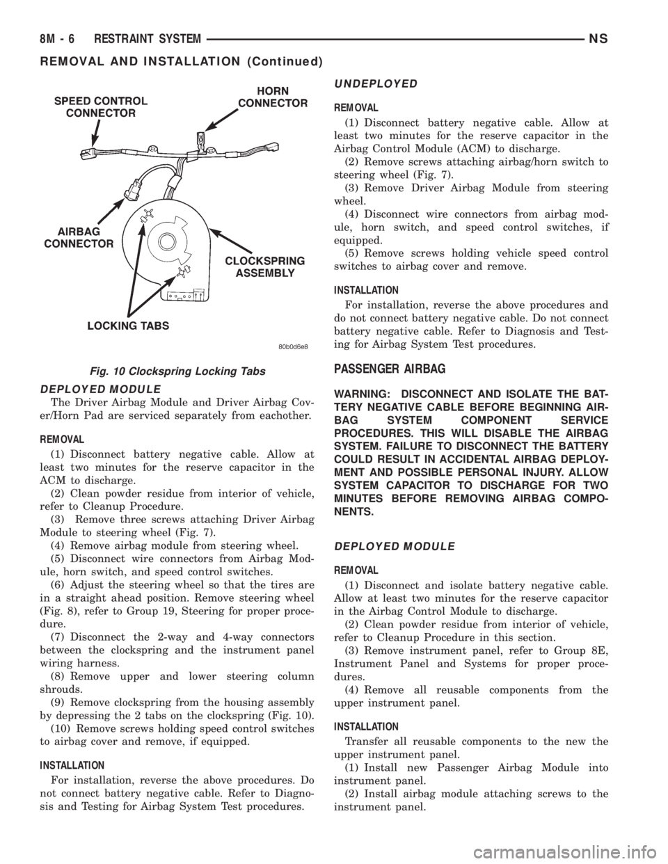
by depressing the 2 tabs on the clockspring (Fig. 10).
(10) Remove screws holding speed control switches
to airbag cover and remove, if equipped.
INSTALLATION
For installation, reverse the above procedures. Do
not connect battery negative cable. Refer to Diagno-
sis and Testing for Airbag System Test procedures.
UNDEPLOYED
REMOVAL
(1) Disconnect battery negative cable. Allow at
least two minutes for the reserve capacitor in the
Airbag Control Module (ACM) to discharge.
(2) Remove screws attaching airbag/horn switch to
steering wheel (Fig. 7).
(3) Remove Driver Airbag Module from steering
wheel.
(4) Disconnect wire connectors from airbag mod-
ule, horn switch, and speed control switches, if
equipped.
(5) Remove screws holding vehicle speed control
switches to airbag cover and remove.
INSTALLATION
For installation, reverse the above procedures and
do not connect battery negative cable. Do not connect
battery negative cable. Refer to Diagnosis and Test-
ing for Airbag System Test procedures.
PASSENGER AIRBAG
WARNING: DISCONNECT AND ISOLATE THE BAT-
TERY NEGATIVE CABLE BEFORE BEGINNING AIR-
BAG SYSTEM COMPONENT SERVICE
PROCEDURES. THIS WILL DISABLE THE AIRBAG
SYSTEM. FAILURE TO DISCONNECT THE BATTERY
COULD RESULT IN ACCIDENTAL AIRBAG DEPLOY-
MENT AND POSSIBLE PERSONAL INJURY. ALLOW
SYSTEM CAPACITOR TO DISCHARGE FOR TWO
MINUTES BEFORE REMOVING AIRBAG COMPO-
NENTS.
DEPLOYED MODULE
REMOVAL
(1) Disconnect and isolate battery negative cable.
Allow at least two minutes for the reserve capacitor
in the Airbag Control Module to discharge.
(2) Clean powder residue from interior of vehicle,
refer to Cleanup Procedure in this section.
(3) Remove instrument panel, refer to Group 8E,
Instrument Panel and Systems for proper proce-
dures.
(4) Remove all reusable components from the
upper instrument panel.
INSTALLATION
Transfer all reusable components to the new the
upper instrument panel.
(1) Install new Passenger Airbag Module into
instrument panel.
(2) Install airbag module attaching screws to the
instrument panel.
Fig. 10 Clockspring Locking Tabs
8M - 6 RESTRAINT SYSTEMNS
REMOVAL AND INSTALLATION (Continued)
Page 503 of 1938
(3) Install Instrument panel. Refer to Group 8E,
Instrument Panel and Systems for installation proce-
dures.
(4) Through access holes in instrument panel
above glove box opening, install screws holding air-
bag to back of panel.
(5) Install the bolts attaching forward airbag
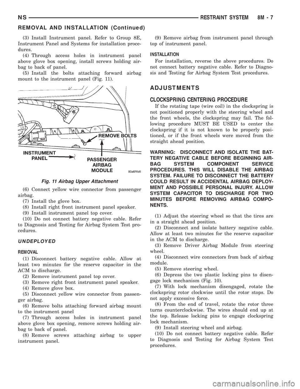
mount to the instrument panel (Fig. 11).
(6) Connect yellow wire connector from passenger
airbag.
(7) Install the glove box.
(8) Install right front instrument panel speaker.
(9) Install instrument panel top cover.
(10) Do not connect battery negative cable. Refer
to Diagnosis and Testing for Airbag System Test pro-
cedures.
UNDEPLOYED
REMOVAL
(1) Disconnect battery negative cable. Allow at
least two minutes for the reserve capacitor in the
ACM to discharge.
(2) Remove instrument panel top cover.
(3) Remove right front instrument panel speaker.
(4) Remove glove box.
(5) Disconnect yellow wire connector from passen-
ger airbag.
(6) Remove bolts attaching forward airbag mount
to the instrument panel
(7) Through access holes in instrument panel
above glove box opening, remove screws holding air-
bag to back of panel.
(8) Remove screws attaching airbag to upper
instrument panel.(9) Remove airbag from instrument panel through
top of instrument panel.
INSTALLATION
For installation, reverse the above procedures. Do
not connect battery negative cable. Refer to Diagno-
sis and Testing for Airbag System Test procedures.
ADJUSTMENTS
CLOCKSPRING CENTERING PROCEDURE
If the rotating tape (wire coil) in the clockspring is
not positioned properly with the steering wheel and
the front wheels, the clockspring may fail. The fol-
lowing procedure MUST BE USED to center the
clockspring if it is not known to be properly posi-
tioned, or if the front wheels were moved from the
straight ahead position.
WARNING: DISCONNECT AND ISOLATE THE BAT-
TERY NEGATIVE CABLE BEFORE BEGINNING AIR-
BAG SYSTEM COMPONENT SERVICE
PROCEDURES. THIS WILL DISABLE THE AIRBAG
SYSTEM. FAILURE TO DISCONNECT THE BATTERY
COULD RESULT IN ACCIDENTAL AIRBAG DEPLOY-
MENT AND POSSIBLE PERSONAL INJURY. ALLOW
SYSTEM CAPACITOR TO DISCHARGE FOR TWO
MINUTES BEFORE REMOVING AIRBAG COMPO-
NENTS.
(1) Adjust the steering wheel so that the tires are
in a straight ahead position.
(2) Disconnect and isolate battery negative cable.
Allow at least two minutes for the reserve capacitor
in the ACM to discharge.
(3) Remove Driver Airbag Module from steering
wheel.
(4) Disconnect wire connectors from back of airbag
module.
(5) Remove steering wheel.
(6) Depress the two plastic locking pins to disen-
gage lock mechanism (Fig. 10).
(7) With lock mechanism disengaged, rotate the
clockspring rotor clockwise until the rotor stops. Do
not apply excessive force.
(8) From the end of travel, rotate the rotor three
turns counterclockwise. The wires should end up at
the top. Release locking pins to engage clockspring
lock mechanism.
(9) Install steering wheel and airbag.
(10) Do not connect battery negative cable. Refer
to Diagnosis and Testing for Airbag System Test
procedures.
Fig. 11 Airbag Upper Attachment
NSRESTRAINT SYSTEM 8M - 7
REMOVAL AND INSTALLATION (Continued)
Page 1076 of 1938
ENGINE ASSEMBLY
REMOVAL
(1) Perform fuel pressure release procedure. Refer
to Group 14, Fuel System for procedure. Remove fuel
line to fuel rail.
(2) Disconnect battery.
(3) Remove Air cleaner and hoses.
(4) Drain cooling system. Refer to Group 7, Cooling
System for procedure.
(5) Remove upper radiator hose and remove radia-
tor fans. Refer to Group 7, Cooling System for proce-
dure.
(6) Remove lower radiator hose.
(7) Disconnect automatic transmission cooler lines
and plug, if equipped.
(8) Disconnect transmission shift linkage.
(9) Disconnect throttle body linkage.
(10) Disconnect engine wiring harness.
(11) Disconnect heater hoses.
(12) Discharge Air Conditioning System. Refer to
Group 24, Air Conditioning for procedure.
(13) Hoist vehicle and remove right inner splash
shield. Remove wheels and tires.
(14) Loosen power steering belt for pump removal.
Refer to Group 7, Cooling System for procedure.
(15) Remove axle shafts. Refer to Group 2, Suspen-
sion and Driveshafts for procedure.
(16) Disconnect exhaust pipe from manifold.
(17) Remove front and rear engine mount brackets
from the body.
(18) Remove bending braces and front engine
mount bracket. Remove transmission inspection
cover.
(19) Mark flexplate to torque converter and
remove torque converter bolts.
(20) Install front engine mount bracket.
(21) Lower vehicle.
(22) Remove power steering pump. Set pump
aside.
(23) Remove A/C lines at compressor and cap.
(24) Remove ground straps to body.
(25) Raise vehicle enough to allow engine dolly
Special Tool 6135, cradle Special Tool 6710 with
Posts Special Tool 6848 and Adaptor Special Tool
8130 to be installed under vehicle (Fig. 27).
(26) Loosen cradle posts to allow movement for
proper positioning. Locate two rear posts (right side
of engine) into the holes on the engine bedplate.
Locate the two front posts (left side of engine) on the
front engine bracket and A/C compressor bracket
(Fig. 27). Lower vehicle and position cradle mounts
until the engine is resting on mounts. Tighten
mounts to cradle frame. This will keep mounts from
moving when removing or installing engine and
transmission.(27) Lower vehicle so the weight ofONLY THE
ENGINE AND TRANSMISSIONare on the cradle.
(28) Remove engine and transmission mount bolts.
(29) Raise vehicle slowly. It may be necessary to
move the engine/transmission assembly on the cradle
to allow for removal around the body.
INSTALLATION
(1) Position engine and transmission assembly
under vehicle and slowly lower the vehicle over the
engine and transmission.
(2) Align engine and transmission mounts to
attaching points. Install mounting bolts at the right
engine and left transmission mounts. Refer to proce-
dures outlined in this section.
(3) Slowly raise vehicle enough to remove the
engine dolly and cradle Special Tools 6135 and 6710.
(4) Install axle shafts. Refer to Group 2, Suspen-
sion and Driveshafts for procedure.
(5) Install transmission and engine braces and
splash shields.
(6) Connect exhaust system to manifold. Refer to
Group 11, Exhaust System and Intake Manifold for
procedure and torque specifications.
(7) Install power steering pump. Refer to Cooling
System Group 7, Accessory Drive Section for belt ten-
sion adjustment.
(8) Install A/C compressor hoses. Refer to Group
24, Heater and Air Conditioning for procedure.
(9) Install accessory drive belts. Refer to Group 7,
Cooling System Accessory Drive Section for belt ten-
sion adjustment.
(10) Install front and rear engine mounts. Refer to
this section for procedure.
(11) Install inner splash shield. Install wheels and
tires.
(12) Connect automatic transmission cooler lines,
and shift linkage. Refer to Group 21, Transmission
for procedures.
(13) Connect fuel line and heater hoses.
(14) Install ground straps. Connect engine and
throttle body connections and harnesses. Refer to
Group 8, Electrical for procedure.
(15) Connect throttle body linkage. Refer to Group
14, Fuel System for procedure.
(16) Install radiator fans. Install radiator hoses.
Fill cooling system. Refer to Group 7, Cooling System
for filling procedure.
(17) Connect battery.
(18) Install air cleaner and hoses.
(19) Install oil filter. Fill engine crankcase with
proper oil to correct level.
(20) Start engine and run until operating temper-
ature is reached.
(21) Adjust transmission linkage, if necessary.
9 - 26 2.4L ENGINENS
REMOVAL AND INSTALLATION (Continued)
Page 1281 of 1938
FRAME AND BUMPERS
CONTENTS
page page
BUMPERS AND FASCIA.................... 1FRAME................................. 3
BUMPERS AND FASCIA
INDEX
page page
REMOVAL AND INSTALLATION
FRONT BUMPER FASCIA.................. 1
FRONT BUMPER REINFORCEMENT.......... 1REAR BUMPER FASCIA................... 2
REAR BUMPER REINFORCEMENT........... 2
REMOVAL AND INSTALLATION
FRONT BUMPER FASCIA
REMOVAL
(1) Release hood latch and open hood.
(2) Remove bolts holding fascia to headlamp
mounting panel at each side of grille.
(3) Hoist and support vehicle on safety stands.
(4) Remove front wheels. Refer to Group 22,
Wheels and Tires, for proper procedures and
sequence.
(5) Remove front wheelhouse splash shields fasten-
ers as necessary to gain access to bolts holding front
fascia to fender. Refer to Group 23, Body, for proper
procedures.
(6) Remove bolts holding fascia to bottom of front
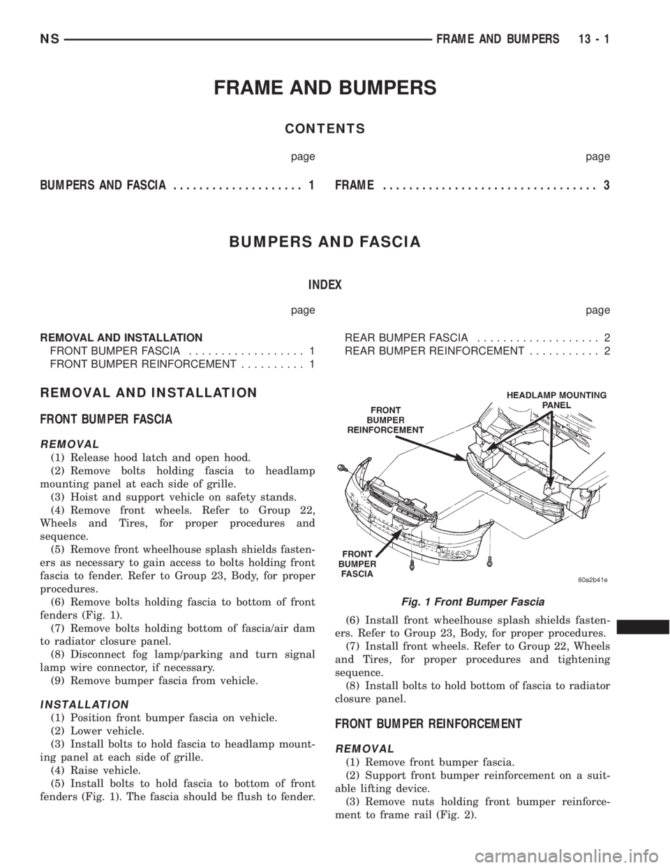
fenders (Fig. 1).
(7) Remove bolts holding bottom of fascia/air dam
to radiator closure panel.
(8) Disconnect fog lamp/parking and turn signal
lamp wire connector, if necessary.
(9) Remove bumper fascia from vehicle.
INSTALLATION
(1) Position front bumper fascia on vehicle.
(2) Lower vehicle.
(3) Install bolts to hold fascia to headlamp mount-
ing panel at each side of grille.
(4) Raise vehicle.
(5) Install bolts to hold fascia to bottom of front
fenders (Fig. 1). The fascia should be flush to fender.(6) Install front wheelhouse splash shields fasten-
ers. Refer to Group 23, Body, for proper procedures.
(7) Install front wheels. Refer to Group 22, Wheels
and Tires, for proper procedures and tightening
sequence.
(8) Install bolts to hold bottom of fascia to radiator
closure panel.FRONT BUMPER REINFORCEMENT
REMOVAL
(1) Remove front bumper fascia.
(2) Support front bumper reinforcement on a suit-
able lifting device.
(3) Remove nuts holding front bumper reinforce-
ment to frame rail (Fig. 2).
Fig. 1 Front Bumper Fascia
NSFRAME AND BUMPERS 13 - 1
Page 1429 of 1938
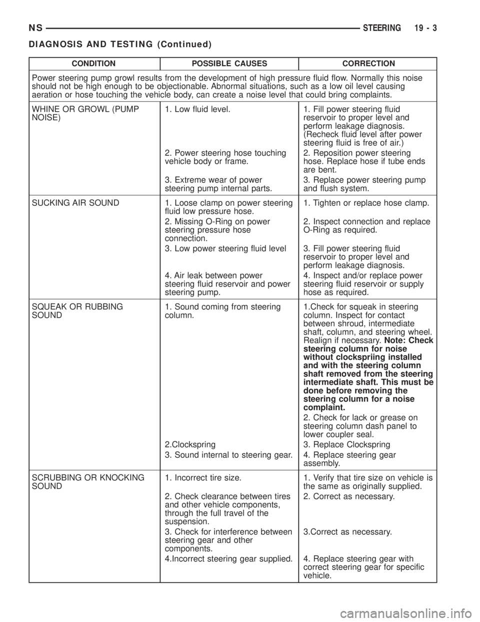
CONDITION POSSIBLE CAUSES CORRECTION
Power steering pump growl results from the development of high pressure fluid flow. Normally this noise
should not be high enough to be objectionable. Abnormal situations, such as a low oil level causing
aeration or hose touching the vehicle body, can create a noise level that could bring complaints.
WHINE OR GROWL (PUMP
NOISE)1. Low fluid level. 1. Fill power steering fluid
reservoir to proper level and
perform leakage diagnosis.
(Recheck fluid level after power
steering fluid is free of air.)
2. Power steering hose touching
vehicle body or frame.2. Reposition power steering
hose. Replace hose if tube ends
are bent.
3. Extreme wear of power
steering pump internal parts.3. Replace power steering pump
and flush system.
SUCKING AIR SOUND 1. Loose clamp on power steering
fluid low pressure hose.1. Tighten or replace hose clamp.
2. Missing O-Ring on power
steering pressure hose
connection.2. Inspect connection and replace
O-Ring as required.
3. Low power steering fluid level 3. Fill power steering fluid
reservoir to proper level and
perform leakage diagnosis.
4. Air leak between power
steering fluid reservoir and power
steering pump.4. Inspect and/or replace power
steering fluid reservoir or supply
hose as required.
SQUEAK OR RUBBING
SOUND1. Sound coming from steering
column.1.Check for squeak in steering
column. Inspect for contact
between shroud, intermediate
shaft, column, and steering wheel.
Realign if necessary.Note: Check
steering column for noise
without clockspriing installed
and with the steering column
shaft removed from the steering
intermediate shaft. This must be
done before removing the
steering column for a noise
complaint.
2. Check for lack or grease on
steering column dash panel to
lower coupler seal.
2.Clockspring 3. Replace Clockspring
3. Sound internal to steering gear. 4. Replace steering gear
assembly.
SCRUBBING OR KNOCKING
SOUND1. Incorrect tire size. 1. Verify that tire size on vehicle is
the same as originally supplied.
2. Check clearance between tires
and other vehicle components,
through the full travel of the
suspension.2. Correct as necessary.
3. Check for interference between
steering gear and other
components.3.Correct as necessary.
4.Incorrect steering gear supplied. 4. Replace steering gear with
correct steering gear for specific
vehicle.
NSSTEERING 19 - 3
DIAGNOSIS AND TESTING (Continued)
Page 1430 of 1938
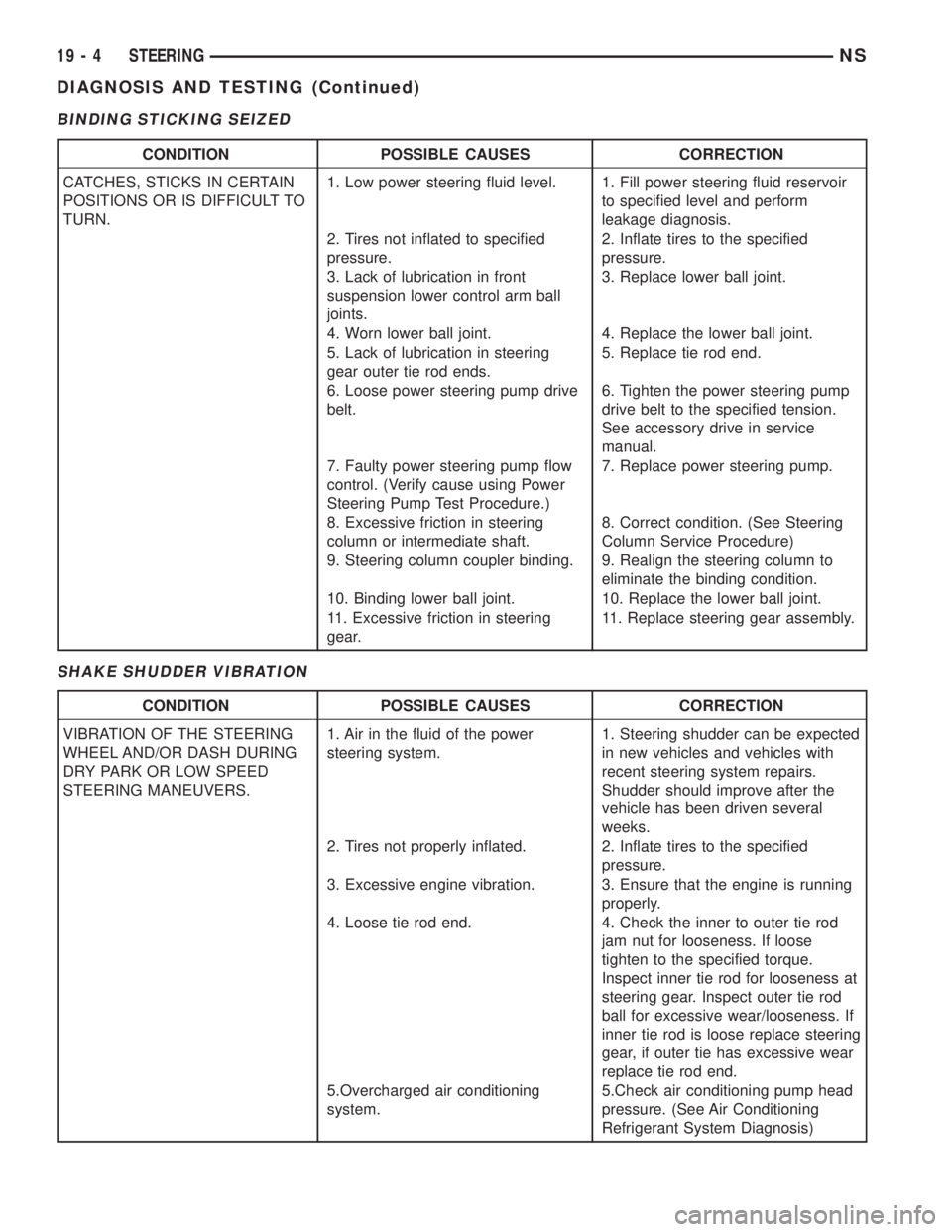
BINDING STICKING SEIZED
SHAKE SHUDDER VIBRATION
CONDITION POSSIBLE CAUSES CORRECTION
CATCHES, STICKS IN CERTAIN
POSITIONS OR IS DIFFICULT TO
TURN.1. Low power steering fluid level. 1. Fill power steering fluid reservoir
to specified level and perform
leakage diagnosis.
2. Tires not inflated to specified
pressure.2. Inflate tires to the specified
pressure.
3. Lack of lubrication in front
suspension lower control arm ball
joints.3. Replace lower ball joint.
4. Worn lower ball joint. 4. Replace the lower ball joint.
5. Lack of lubrication in steering
gear outer tie rod ends.5. Replace tie rod end.
6. Loose power steering pump drive
belt.6. Tighten the power steering pump
drive belt to the specified tension.
See accessory drive in service
manual.
7. Faulty power steering pump flow
control. (Verify cause using Power
Steering Pump Test Procedure.)7. Replace power steering pump.
8. Excessive friction in steering
column or intermediate shaft.8. Correct condition. (See Steering
Column Service Procedure)
9. Steering column coupler binding. 9. Realign the steering column to
eliminate the binding condition.
10. Binding lower ball joint. 10. Replace the lower ball joint.
11. Excessive friction in steering
gear.11. Replace steering gear assembly.
CONDITION POSSIBLE CAUSES CORRECTION
VIBRATION OF THE STEERING
WHEEL AND/OR DASH DURING
DRY PARK OR LOW SPEED
STEERING MANEUVERS.1. Air in the fluid of the power
steering system.1. Steering shudder can be expected
in new vehicles and vehicles with
recent steering system repairs.
Shudder should improve after the
vehicle has been driven several
weeks.
2. Tires not properly inflated. 2. Inflate tires to the specified
pressure.
3. Excessive engine vibration. 3. Ensure that the engine is running
properly.
4. Loose tie rod end. 4. Check the inner to outer tie rod
jam nut for looseness. If loose
tighten to the specified torque.
Inspect inner tie rod for looseness at
steering gear. Inspect outer tie rod
ball for excessive wear/looseness. If
inner tie rod is loose replace steering
gear, if outer tie has excessive wear
replace tie rod end.
5.Overcharged air conditioning
system.5.Check air conditioning pump head
pressure. (See Air Conditioning
Refrigerant System Diagnosis)
19 - 4 STEERINGNS
DIAGNOSIS AND TESTING (Continued)