1996 CHRYSLER VOYAGER heating
[x] Cancel search: heatingPage 1331 of 1938
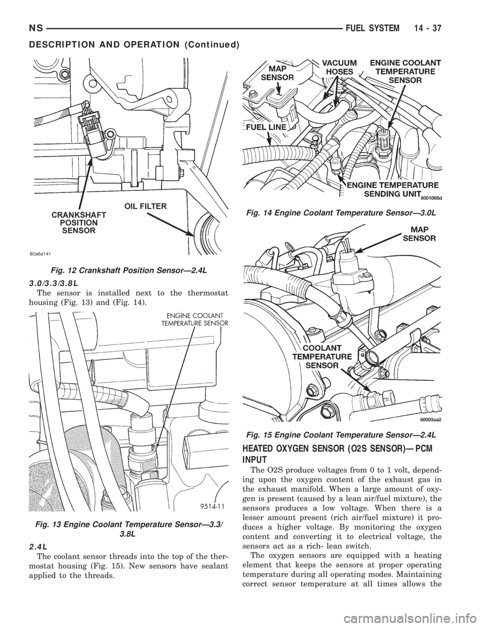
3.0/3.3/3.8L
The sensor is installed next to the thermostat
housing (Fig. 13) and (Fig. 14).
2.4L
The coolant sensor threads into the top of the ther-
mostat housing (Fig. 15). New sensors have sealant
applied to the threads.
HEATED OXYGEN SENSOR (O2S SENSOR)ÐPCM
INPUT
The O2S produce voltages from 0 to 1 volt, depend-
ing upon the oxygen content of the exhaust gas in
the exhaust manifold. When a large amount of oxy-
gen is present (caused by a lean air/fuel mixture), the
sensors produces a low voltage. When there is a
lesser amount present (rich air/fuel mixture) it pro-
duces a higher voltage. By monitoring the oxygen
content and converting it to electrical voltage, the
sensors act as a rich- lean switch.
The oxygen sensors are equipped with a heating
element that keeps the sensors at proper operating
temperature during all operating modes. Maintaining
correct sensor temperature at all times allows the
Fig. 12 Crankshaft Position SensorÐ2.4L
Fig. 13 Engine Coolant Temperature SensorÐ3.3/
3.8L
Fig. 14 Engine Coolant Temperature SensorÐ3.0L
Fig. 15 Engine Coolant Temperature SensorÐ2.4L
NSFUEL SYSTEM 14 - 37
DESCRIPTION AND OPERATION (Continued)
Page 1332 of 1938
system to enter into closed loop operation sooner.
Also, it allows the system to remain in closed loop
operation during periods of extended idle.
In Closed Loop operation the PCM monitors the
O2S input (along with other inputs) and adjusts the
injector pulse width accordingly. During Open Loop
operation the PCM ignores the O2 sensor input. The
PCM adjusts injector pulse width based on prepro-
grammed (fixed) values and inputs from other sen-
sors.
The Automatic Shutdown (ASD) relay supplies bat-
tery voltage to both the upstream and downstream
heated oxygen sensors. The oxygen sensors are
equipped with a heating element. The heating ele-
ments reduce the time required for the sensors to
reach operating temperature.
UPSTREAM HEATED OXYGEN SENSOR
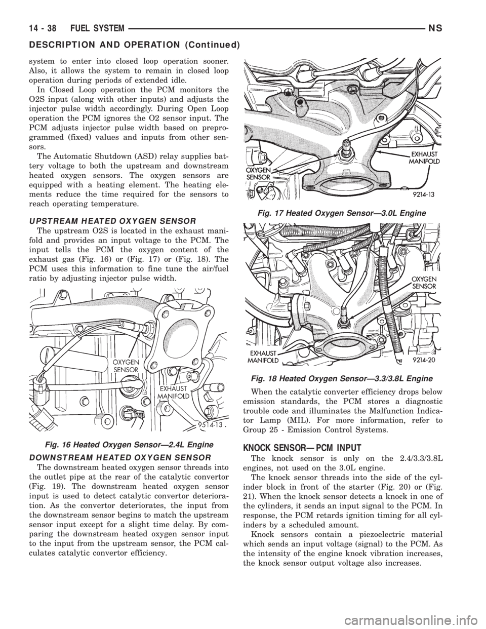
The upstream O2S is located in the exhaust mani-
fold and provides an input voltage to the PCM. The
input tells the PCM the oxygen content of the
exhaust gas (Fig. 16) or (Fig. 17) or (Fig. 18). The
PCM uses this information to fine tune the air/fuel
ratio by adjusting injector pulse width.
DOWNSTREAM HEATED OXYGEN SENSOR
The downstream heated oxygen sensor threads into
the outlet pipe at the rear of the catalytic convertor
(Fig. 19). The downstream heated oxygen sensor
input is used to detect catalytic convertor deteriora-
tion. As the convertor deteriorates, the input from
the downstream sensor begins to match the upstream
sensor input except for a slight time delay. By com-
paring the downstream heated oxygen sensor input
to the input from the upstream sensor, the PCM cal-
culates catalytic convertor efficiency.When the catalytic converter efficiency drops below
emission standards, the PCM stores a diagnostic
trouble code and illuminates the Malfunction Indica-
tor Lamp (MIL). For more information, refer to
Group 25 - Emission Control Systems.
KNOCK SENSORÐPCM INPUT
The knock sensor is only on the 2.4/3.3/3.8L
engines, not used on the 3.0L engine.
The knock sensor threads into the side of the cyl-
inder block in front of the starter (Fig. 20) or (Fig.
21). When the knock sensor detects a knock in one of
the cylinders, it sends an input signal to the PCM. In
response, the PCM retards ignition timing for all cyl-
inders by a scheduled amount.
Knock sensors contain a piezoelectric material
which sends an input voltage (signal) to the PCM. As
the intensity of the engine knock vibration increases,
the knock sensor output voltage also increases.
Fig. 16 Heated Oxygen SensorÐ2.4L Engine
Fig. 17 Heated Oxygen SensorÐ3.0L Engine
Fig. 18 Heated Oxygen SensorÐ3.3/3.8L Engine
14 - 38 FUEL SYSTEMNS
DESCRIPTION AND OPERATION (Continued)
Page 1336 of 1938

in the engine compartment next to the battery (Fig.
30). A label affixed to the underside of the PDC cover
identifies the relays and fuses in the PDC.
GENERATOR FIELDÐPCM OUTPUT
The PCM regulates the charging system voltage
within a range of 12.9 to 15.0 volts. Refer to Group
8A for Battery system information and 8C for charg-
ing system information.
AUTOMATIC SHUTDOWN RELAYÐPCM OUTPUT
The Automatic Shutdown (ASD) relay supplies bat-
tery voltage to the fuel injectors, electronic ignition
coil and the heating elements in the oxygen sensors.
A buss bar in the Power Distribution Center (PDC)
supplies voltage to the solenoid side and contact side
of the relay. The ASD relay power circuit contains a
25 amp fuse between the buss bar in the PDC and
the relay. The fuse is located in the PDC. Refer to
Group 8W, Wiring Diagrams for circuit information.
The PCM controls the relay by switching the
ground path for the solenoid side of the relay on and
off. The PCM turns the ground path off when the
ignition switch is in the Off position unless the 02
Heater Monitor test is being run. Refer to Group 25,
On-Board Diagnostics. When the ignition switch is in
the On or Crank position, the PCM monitors the
crankshaft position sensor and camshaft position sen-
sor signals to determine engine speed and ignition
timing (coil dwell). If the PCM does not receive the
crankshaft position sensor and camshaft position sen-
sor signals when the ignition switch is in the Run
position, it will de-energize the ASD relay.The ASD relay is located in the PDC (Fig. 30). A
label affixed to the underside of the PDC cover iden-
tifies the relays and fuses in the PDC.
FUEL PUMP RELAYÐPCM OUTPUT
The fuel pump relay supplies battery voltage to the
fuel pump. The fuel pump relay power circuit con-
tains a 9 amp fuse. The fuse is located in the PDC.
Refer to Group 8W, Wiring Diagrams for circuit infor-
mation.
The PCM controls the fuel pump relay by switch-
ing the ground path for the solenoid side of the relay
on and off. The PCM turns the ground path off when
the ignition switch is in the Off position. When the
ignition switch is in the On position, the PCM ener-
gizes the fuel pump. If the crankshaft position sensor
does not detect engine rotation, the PCM de-ener-
gizes the relay after approximately one second.
The fuel pump relay is located in the PDC (Fig.
30). A label affixed to the underside of the PDC cover
identifies the relays and fuses in the PDC.
STARTER RELAYÐPCM OUTPUT
Double Start Override ia a feature that prevents
the starter from operating if the engine is already
running. This feature is accomplished with software
only. There was no hardware added because of this
feature. To incorporate the unique feature of Double
Start Override, it was necessary to use the PCM
(software) to control the starter circuit. To use the
PCM it was necessary to separate the starter relay
coil ground from the park neutral switch. The starter
relay ground is now controlled through Pin 60 of the
PCM. This allows the PCM to interrupt the ground
circuit if other inputs tell it that the engine is turn-
ing. If the starter system is operating properly, it can
be assumed that the override protection is also work-
ing.
IDLE AIR CONTROL MOTORÐPCM OUTPUT
The idle air control motor is mounted on the throt-
tle body. The PCM operates the idle air control motor
(Fig. 26) or (Fig. 27) or (Fig. 28). The PCM adjusts
engine idle speed through the idle air control motor
to compensate for engine load or ambient conditions.
The throttle body has an air bypass passage that
provides air for the engine at idle (the throttle blade
is closed). The idle air control motor pintle protrudes
into the air bypass passage and regulates air flow
through it.
The PCM adjusts engine idle speed by moving the
idle air control motor pintle in and out of the bypass
passage. The adjustments are based on inputs the
PCM receives. The inputs are from the throttle posi-
tion sensor, crankshaft position sensor, coolant tem-
perature sensor, and various switch operations
Fig. 30 Power Distribution Center (PDC)
14 - 42 FUEL SYSTEMNS
DESCRIPTION AND OPERATION (Continued)
Page 1355 of 1938
PCM. If OK, replace MAP sensor. If not OK, repair or
replace the wire harness as required.
HEATED OXYGEN SENSOR
Use an ohmmeter to test the heating element of
the oxygen sensors. Disconnect the electrical connec-
tor from each oxygen sensor. The white wires in the
sensor connector are the power and ground circuits
for the heater. Connect the ohmmeter test leads to
terminals of the white wires in the heated oxygen
sensor connector. Replace the heated oxygen sensor if
the resistance is not between 4 and 7 ohms.
KNOCK SENSOR
The engine knock sensor is affected by a number of
factors. A few of these are: ignition timing, cylinder
pressure, fuel octane, etc. The knock sensor gener-
ates an AC voltage whose amplitude increases with
the increase of engine knock. The knock sensor can
be tested with a digital voltmeter. The RMS voltage
starts at about 20mVac (at about 700 rpm) and
increases to approximately 600 mVac (5000 rpm). If
the output falls outside of this range a DTC will be
set.
CAMSHAFT AND CRANKSHAFT POSITION SENSOR
Refer to Group 8D, Ignition for Diagnosis and Test-
ing of Camshaft and Crankshaft Sensors.
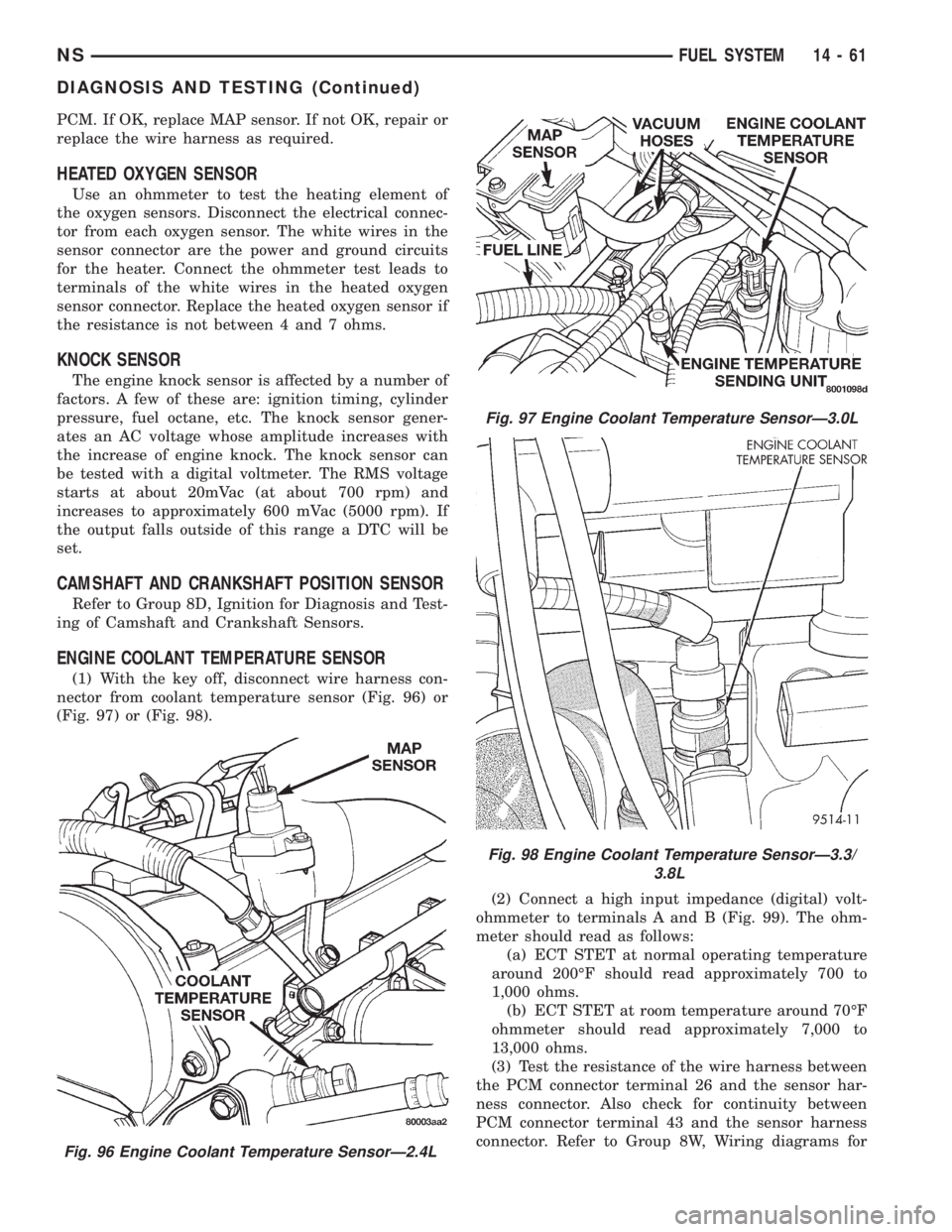
ENGINE COOLANT TEMPERATURE SENSOR
(1) With the key off, disconnect wire harness con-
nector from coolant temperature sensor (Fig. 96) or
(Fig. 97) or (Fig. 98).
(2) Connect a high input impedance (digital) volt-
ohmmeter to terminals A and B (Fig. 99). The ohm-
meter should read as follows:
(a) ECT STET at normal operating temperature
around 200ÉF should read approximately 700 to
1,000 ohms.
(b) ECT STET at room temperature around 70ÉF
ohmmeter should read approximately 7,000 to
13,000 ohms.
(3) Test the resistance of the wire harness between
the PCM connector terminal 26 and the sensor har-
ness connector. Also check for continuity between
PCM connector terminal 43 and the sensor harness
connector. Refer to Group 8W, Wiring diagrams for
Fig. 96 Engine Coolant Temperature SensorÐ2.4L
Fig. 97 Engine Coolant Temperature SensorÐ3.0L
Fig. 98 Engine Coolant Temperature SensorÐ3.3/
3.8L
NSFUEL SYSTEM 14 - 61
DIAGNOSIS AND TESTING (Continued)
Page 1417 of 1938
±cycle, the lower the advance. The lower the duty-
±cycle, the more advanced the fuel timing.
The duty±cycle is determined by the PCM from
inputs it receives from the fuel injector sensor and
engine speed sensor.
TACHOMETERÐPCM OUTPUT
The PCM supplies engine rpm values to the Body
Controller that then supplies the instrument cluster
mounted tachometer (if equipped). Refer to Group 8E
for tachometer information.
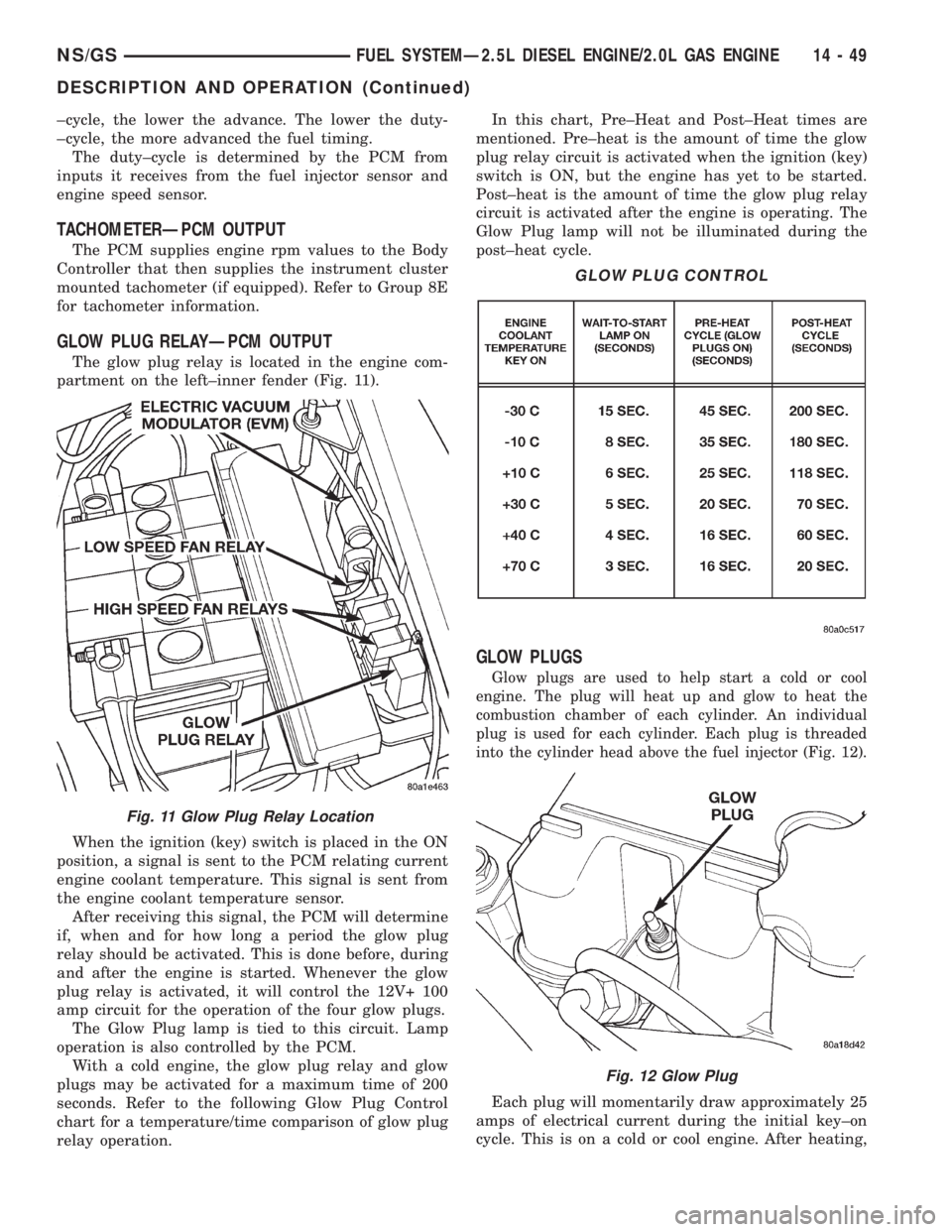
GLOW PLUG RELAYÐPCM OUTPUT
The glow plug relay is located in the engine com-
partment on the left±inner fender (Fig. 11).
When the ignition (key) switch is placed in the ON
position, a signal is sent to the PCM relating current
engine coolant temperature. This signal is sent from
the engine coolant temperature sensor.
After receiving this signal, the PCM will determine
if, when and for how long a period the glow plug
relay should be activated. This is done before, during
and after the engine is started. Whenever the glow
plug relay is activated, it will control the 12V+ 100
amp circuit for the operation of the four glow plugs.
The Glow Plug lamp is tied to this circuit. Lamp
operation is also controlled by the PCM.
With a cold engine, the glow plug relay and glow
plugs may be activated for a maximum time of 200
seconds. Refer to the following Glow Plug Control
chart for a temperature/time comparison of glow plug
relay operation.In this chart, Pre±Heat and Post±Heat times are
mentioned. Pre±heat is the amount of time the glow
plug relay circuit is activated when the ignition (key)
switch is ON, but the engine has yet to be started.
Post±heat is the amount of time the glow plug relay
circuit is activated after the engine is operating. The
Glow Plug lamp will not be illuminated during the
post±heat cycle.
GLOW PLUGS
Glow plugs are used to help start a cold or cool
engine. The plug will heat up and glow to heat the
combustion chamber of each cylinder. An individual
plug is used for each cylinder. Each plug is threaded
into the cylinder head above the fuel injector (Fig. 12).
Each plug will momentarily draw approximately 25
amps of electrical current during the initial key±on
cycle. This is on a cold or cool engine. After heating,
Fig. 11 Glow Plug Relay Location
GLOW PLUG CONTROL
Fig. 12 Glow Plug
NS/GSFUEL SYSTEMÐ2.5L DIESEL ENGINE/2.0L GAS ENGINE 14 - 49
DESCRIPTION AND OPERATION (Continued)
Page 1439 of 1938
(18) Remove the 3 previously loosened bolts
attaching the front bracket to the power steering
pump and separate the power steering pump from
the front bracket prior to removing the pump from
the vehicle.
(19) The power steering pump is removed from the
vehicle by pulling it out through the exhaust tunnel
area in the floor pan of the vehicle.
INSTALL
(1) Install power steering pump back in vehicle
using the reverse order of its removal through the
exhaust tunnel are of the vehicle.
(2) Install the power steering pump on its cast
mounting bracket and loosely install nut to hold
pump in place (Fig. 9).
(3) Install the front bracket on the power steering
pump and loosely install the 3 mounting bolts (Fig.
10). Then install the nut and bolt attaching the front
bracket to the cast bracket (Fig. 10).
(4) Tighten the 3 power steering pump mounting
bolts (Fig. 10) to a torque of 54 N´m (40 ft. lbs.).
NOTE: Before installing power steering fluid pres-
sure hose on power steering pump, inspect the
O-ring on the pressure hose for damage and
replace if necessary.
(5) Install the power steering fluid pressure line
onto the output fitting of the power steering pump
(Fig. 8). Tighten the pressure line to pump fitting
tube nut to a torque of 31 N´m (275 in. lbs.).
(6) Install the power steering fluid, low pressure
return hose on the power steering pump low pressure
fitting (Fig. 8).Be sure hose clamps are properly
reinstalled.
(7) Install the power steering fluid supply hose
from the power steering fluid reservoir, on the power
steering pump fluid fitting (Fig. 7).Be sure hose is
clear of accessory drive belts all hose clamps
are properly reinstalled.
(8) Install the power steering pump drive belt on
pulley. See Cooling, Group 7 for detailed installation
procedure.
(9) Install the accessory drive splash shield (Fig.
6).
(10) Install the power steering fluid return hose on
the steel tube at the front suspension cradle (Fig. 5).
(11) Install a screw type hose clamp on the power
steering hose to steel tube connection.Be sure hose
clamps are properly reinstalled.Tighten the screw
clamp to a torque of 2 N´m (18 in. lbs.).
CAUTION: The protective heat shield sleeves must
cover the entire rubber hose and hose to tube con-
nection portion of both the power steering fluid
pressure and return hoses (Fig. 5). This is requiredto prevent the overheating of the power steering
hoses.
(12) When used, properly position the protective
heat sleeves on the power steering hoses (Fig. 5).
Then, tie strap the heat sleeves to the power steering
hoses to keep them in their proper position.
(13) Install the exhaust pipe on the exhaust man-
ifold. Install all exhaust system hangers/isolators on
the exhaust system brackets.
(14) Connect the oxygen sensor wiring harness to
the vehicle wiring harness. Install wiring harness
grommet in the floor pan of the vehicle.
(15) Lower vehicle.
(16) Adjust the power steering pump drive belt.
See Cooling, Group 7 for detailed adjustment proce-
dure.
(17) Tighten the top nut and bottom bolt on the
power steering pump front mounting bracket (Fig. 3)
to a torque of 54 N´m (40 ft. lbs.).
CAUTION: Do not use automatic transmission fluid
in power steering system. Only use MoparT, Power
Steering Fluid, or equivalent.
(18) Fill the remote power steering pump fluid res-
ervoir to correct fluid level.
(19) Install cap on power steering fluid reservoir.
(20) Connect the negative battery cable on the
negative battery post.
(21) Start engine and turn steering wheel several
times from stop to stop to bleed air from fluid in sys-
tem. Stop engine, check fluid level, and inspect sys-
tem for leaks. See Checking Fluid Level.
3.0 LITER POWER STEERING PUMP
REMOVE
WARNING: POWER STEERING OIL, ENGINE COM-
PONENTS AND THE EXHAUST SYSTEM MAY BE
EXTREMELY HOT IF ENGINE HAS BEEN RUNNING.
DO NOT START ENGINE WITH ANY LOOSE OR DIS-
CONNECTED HOSES. DO NOT ALLOW HOSES TO
TOUCH HOT EXHAUST MANIFOLD OR CATALYST.
(1) Remove the (-) negative battery cable from the
battery and isolate cable.
(2) Remove cap from power steering fluid reser-
voir.
(3) Using a siphon pump, remove as much power
steering fluid as possible from the power steering
fluid reservoir.
NSSTEERING 19 - 13
REMOVAL AND INSTALLATION (Continued)
Page 1441 of 1938
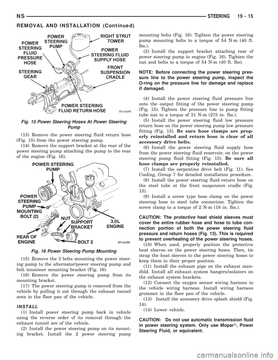
(13) Remove the power steering fluid return hose
(Fig. 15) from the power steering pump.
(14) Remove the support bracket at the rear of the
power steering pump attaching the pump to the rear
of the engine (Fig. 16).
(15) Remove the 2 bolts mounting the power steer-
ing pump to the alternator/power steering pump and
belt tensioner mounting bracket (Fig. 16).
(16) Remove the power steering pump from its
mounting bracket.
(17) The power steering pump is removed from the
vehicle by pulling it out through the exhaust tunnel
area in the floor pan of the vehicle.
INSTALL
(1) Install power steering pump back in vehicle
using the reverse order of its removal through the
exhaust tunnel are of the vehicle.
(2) Install the power steering pump on its mount-
ing bracket. Install the 2 power steering pumpmounting bolts (Fig. 16). Tighten the power steering
pump mounting bolts to a torque of 54 N´m (40 ft.
lbs.).
(3) Install the support bracket attaching rear of
power steering pump to engine (Fig. 16). Tighten the
nut and bolts to a torque of 54 N´m (40 ft. lbs).
NOTE: Before connecting the power steering pres-
sure line to the power steering pump, inspect the
O-ring on the pressure line for damage and replace
if damaged.
(4) Install the power steering fluid pressure line
onto the output fitting of the power steering pump
(Fig. 15). Tighten the pressure line to pump fitting
tube nut to a torque of 31 N´m (275 in. lbs.).
(5) Install the power steering fluid low pressure
return hose on the power steering pump low pressure
fitting (Fig. 15).Be sure hose clamps are prop-
erly reinstalled and return hose is clear of all
accessory drive belts.
(6) Install the power steering fluid supply hose
from the power steering fluid reservoir, on the power
steering pump fluid fitting (Fig. 15).Be sure all
hose clamps are properly reinstalled.
(7) Install the serpentine drive belt (Fig. 11). See
Cooling, Group 7 for detailed installation procedure.
(8) Install the power steering fluid return hose on
the steel tube at the front suspension cradle (Fig.
13).
(9) Install a screw type hose clamp on the power
steering hose to steel tube connection. Tighten the
screw clamp to a torque of 2 N´m (18 in. lbs.).
CAUTION: The protective heat shield sleeves must
cover the entire rubber hose and hose to tube con-
nection portion of both the power steering fluid
pressure and return hoses (Fig. 13). This is required
to prevent overheating of the power steering hoses.
(10) When used, properly position the protective
heat sleeves on the power steering hoses. Then, tie
strap the heat sleeves to the power steering hoses to
keep them in their proper position.
(11) Install the exhaust pipe on the exhaust man-
ifold. Install all exhaust system hangers/isolators on
the exhaust system brackets.
(12) Connect the oxygen sensor wiring harness to
the vehicle wiring harness. Install wiring harness
grommet in the floor pan of the vehicle.
(13) Install the accessory drive splash shield (Fig.
14).
(14) Lower vehicle.
CAUTION: Do not use automatic transmission fluid
in power steering system. Only use MoparT, Power
Steering Fluid, or equivalent.
Fig. 15 Power Steering Hoses At Power Steering
Pump
Fig. 16 Power Steering Pump Mounting
NSSTEERING 19 - 15
REMOVAL AND INSTALLATION (Continued)
Page 1447 of 1938
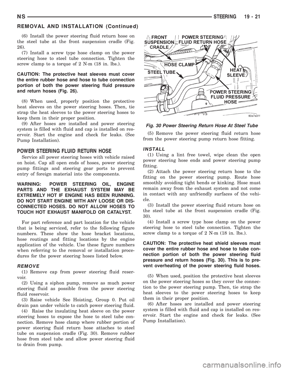
(6) Install the power steering fluid return hose on
the steel tube at the front suspension cradle (Fig.
26).
(7) Install a screw type hose clamp on the power
steering hose to steel tube connection. Tighten the
screw clamp to a torque of 2 N´m (18 in. lbs.).
CAUTION: The protective heat sleeves must cover
the entire rubber hose and hose to tube connection
portion of both the power steering fluid pressure
and return hoses (Fig. 26).
(8) When used, properly position the protective
heat sleeves on the power steering hoses. Then, tie
strap the heat sleeves to the power steering hoses to
keep them in their proper position.
(9) After hoses are installed and power steering
system is filled with fluid and cap is installed on res-
ervoir. Start the engine and check for leaks. (See
Pump Installation).
POWER STEERING FLUID RETURN HOSE
Service all power steering hoses with vehicle raised
on hoist. Cap all open ends of hoses, power steering
pump fittings and steering gear ports to prevent
entry of foreign material into the components.
WARNING: POWER STEERING OIL, ENGINE
PARTS AND THE EXHAUST SYSTEM MAY BE
EXTREMELY HOT IF ENGINE HAS BEEN RUNNING.
DO NOT START ENGINE WITH ANY LOOSE OR DIS-
CONNECTED HOSES. DO NOT ALLOW HOSES TO
TOUCH HOT EXHAUST MANIFOLD OR CATALYST.
For part reference and part location for the vehicle
that is being serviced, refer to the following figure
numbers. These show the hose bracket locations,
hose routings and fitting locations by the engine
application of the vehicle. Use these figure numbers
when referring to the removal or installation proce-
dures for the power steering hoses listed below.
REMOVE
(1) Remove cap from power steering fluid reser-
voir.
(2) Using a siphon pump, remove as much power
steering fluid as possible from the power steering
fluid reservoir.
(3) Raise vehicle See Hoisting, Group 0. Put oil
drain pan under vehicle to catch power steering fluid.
(4) Raise the insulating heat sleeve on the power
steering hoses to expose the hose to steel tube con-
nection. Remove hose clamp where rubber portion of
power steering fluid return hose attaches to steel
tube on suspension cradle (Fig. 30). Remove rubber
hose from steel tube and allow power steering fluid
to drain from pump.(5) Remove the power steering fluid return hose
from the power steering pump return hose fitting.
INSTALL
(1) Using a lint free towel, wipe clean the open
power steering hose ends and power steering pump
fitting.
(2) Attach the power steering return hose to the
fitting on the power steering pump. Route hose
smoothly avoiding tight bends or kinking. Hose must
remain away from the exhaust system and not come
in contact with any unfriendly surfaces of the vehi-
cle.
(3) Install the power steering fluid return hose on
the steel tube at the front suspension cradle (Fig.
30).
(4) Install a screw type hose clamp on the power
steering hose to steel tube connection. Tighten the
screw clamp to a torque of 2 N´m (18 in. lbs.).
CAUTION: The protective heat shield sleeves must
cover the entire rubber hose and hose to tube con-
nection portion of both the power steering fluid
pressure and return hoses (Fig. 30). This is to pre-
vent overheating of the power steering fluid hoses.
(5) When used, position the protective heat sleeves
on the power steering hoses so they cover the connec-
tion to the power steering pump. Then, tie strap the
heat sleeves to the power steering hoses to keep
them in their proper position.
(6) After hoses are installed and power steering
system is filled with fluid and cap is installed on res-
ervoir. Start the engine and check for leaks. (See
Pump Installation).
Fig. 30 Power Steering Return Hose At Steel Tube
NSSTEERING 19 - 21
REMOVAL AND INSTALLATION (Continued)