1996 CHRYSLER VOYAGER heating
[x] Cancel search: heatingPage 1903 of 1938

(4) Install PANEL door actuator gear. Align master
spline of PANEL door actuator gear to master spline
on PANEL door. Position actuator gear within cam
wheel track.
(5) Install DEFROST door actuator gear to hous-
ing. Match master spline of DEFROST door actuatorto master spline on DEFROST door. Position actuator
gear within cam wheel track.
(6) Reinstall housing in vehicle.
(7) Perform the HVAC control Calibration Diagnos-
tic and Cooldown test.
NS/GSHEATING AND AIR CONDITIONING 24 - 37
DISASSEMBLY AND ASSEMBLY (Continued)
Page 1910 of 1938

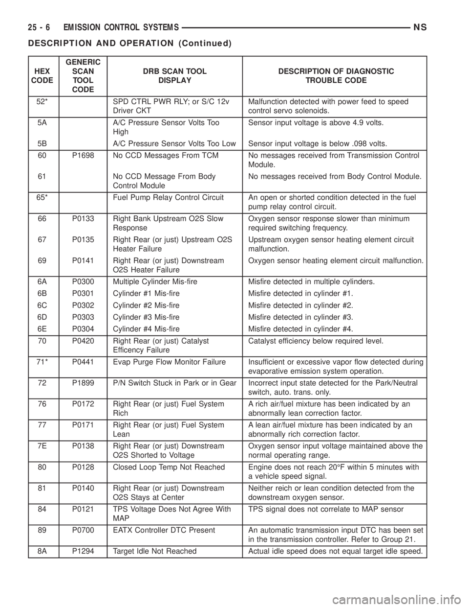
HEX
CODEGENERIC
SCAN
TOOL
CODEDRB SCAN TOOL
DISPLAYDESCRIPTION OF DIAGNOSTIC
TROUBLE CODE
52* SPD CTRL PWR RLY; or S/C 12v
Driver CKTMalfunction detected with power feed to speed
control servo solenoids.
5A A/C Pressure Sensor Volts Too
HighSensor input voltage is above 4.9 volts.
5B A/C Pressure Sensor Volts Too Low Sensor input voltage is below .098 volts.
60 P1698 No CCD Messages From TCM No messages received from Transmission Control
Module.
61 No CCD Message From Body
Control ModuleNo messages received from Body Control Module.
65* Fuel Pump Relay Control Circuit An open or shorted condition detected in the fuel
pump relay control circuit.
66 P0133 Right Bank Upstream O2S Slow
ResponseOxygen sensor response slower than minimum
required switching frequency.
67 P0135 Right Rear (or just) Upstream O2S
Heater FailureUpstream oxygen sensor heating element circuit
malfunction.
69 P0141 Right Rear (or just) Downstream
O2S Heater FailureOxygen sensor heating element circuit malfunction.
6A P0300 Multiple Cylinder Mis-fire Misfire detected in multiple cylinders.
6B P0301 Cylinder #1 Mis-fire Misfire detected in cylinder #1.
6C P0302 Cylinder #2 Mis-fire Misfire detected in cylinder #2.
6D P0303 Cylinder #3 Mis-fire Misfire detected in cylinder #3.
6E P0304 Cylinder #4 Mis-fire Misfire detected in cylinder #4.
70 P0420 Right Rear (or just) Catalyst
Efficency FailureCatalyst efficiency below required level.
71* P0441 Evap Purge Flow Monitor Failure Insufficient or excessive vapor flow detected during
evaporative emission system operation.
72 P1899 P/N Switch Stuck in Park or in Gear Incorrect input state detected for the Park/Neutral
switch, auto. trans. only.
76 P0172 Right Rear (or just) Fuel System
RichA rich air/fuel mixture has been indicated by an
abnormally lean correction factor.
77 P0171 Right Rear (or just) Fuel System
LeanA lean air/fuel mixture has been indicated by an
abnormally rich correction factor.
7E P0138 Right Rear (or just) Downstream
O2S Shorted to VoltageOxygen sensor input voltage maintained above the
normal operating range.
80 P0128 Closed Loop Temp Not Reached Engine does not reach 20ÉF within 5 minutes with
a vehicle speed signal.
81 P0140 Right Rear (or just) Downstream
O2S Stays at CenterNeither reich or lean condition detected from the
downstream oxygen sensor.
84 P0121 TPS Voltage Does Not Agree With
MAPTPS signal does not correlate to MAP sensor
89 P0700 EATX Controller DTC Present An automatic transmission input DTC has been set
in the transmission controller. Refer to Group 21.
8A P1294 Target Idle Not Reached Actual idle speed does not equal target idle speed.
25 - 6 EMISSION CONTROL SYSTEMSNS
DESCRIPTION AND OPERATION (Continued)
Page 1912 of 1938

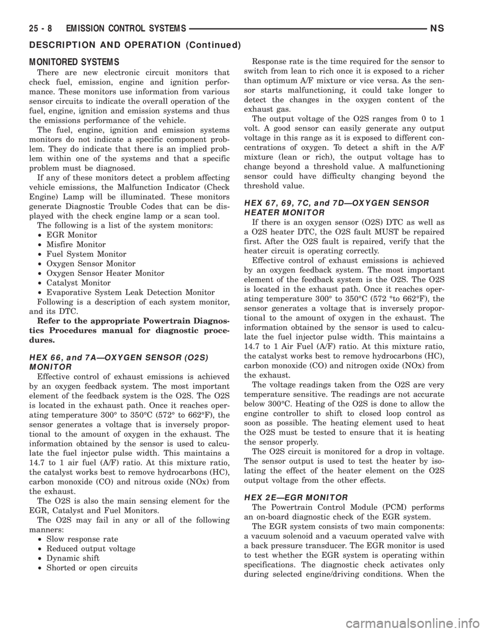
MONITORED SYSTEMS
There are new electronic circuit monitors that
check fuel, emission, engine and ignition perfor-
mance. These monitors use information from various
sensor circuits to indicate the overall operation of the
fuel, engine, ignition and emission systems and thus
the emissions performance of the vehicle.
The fuel, engine, ignition and emission systems
monitors do not indicate a specific component prob-
lem. They do indicate that there is an implied prob-
lem within one of the systems and that a specific
problem must be diagnosed.
If any of these monitors detect a problem affecting
vehicle emissions, the Malfunction Indicator (Check
Engine) Lamp will be illuminated. These monitors
generate Diagnostic Trouble Codes that can be dis-
played with the check engine lamp or a scan tool.
The following is a list of the system monitors:
²EGR Monitor
²Misfire Monitor
²Fuel System Monitor
²Oxygen Sensor Monitor
²Oxygen Sensor Heater Monitor
²Catalyst Monitor
²Evaporative System Leak Detection Monitor
Following is a description of each system monitor,
and its DTC.
Refer to the appropriate Powertrain Diagnos-
tics Procedures manual for diagnostic proce-
dures.
HEX 66, and 7AÐOXYGEN SENSOR (O2S)
MONITOR
Effective control of exhaust emissions is achieved
by an oxygen feedback system. The most important
element of the feedback system is the O2S. The O2S
is located in the exhaust path. Once it reaches oper-
ating temperature 300É to 350ÉC (572É to 662ÉF), the
sensor generates a voltage that is inversely propor-
tional to the amount of oxygen in the exhaust. The
information obtained by the sensor is used to calcu-
late the fuel injector pulse width. This maintains a
14.7 to 1 air fuel (A/F) ratio. At this mixture ratio,
the catalyst works best to remove hydrocarbons (HC),
carbon monoxide (CO) and nitrous oxide (NOx) from
the exhaust.
The O2S is also the main sensing element for the
EGR, Catalyst and Fuel Monitors.
The O2S may fail in any or all of the following
manners:
²Slow response rate
²Reduced output voltage
²Dynamic shift
²Shorted or open circuitsResponse rate is the time required for the sensor to
switch from lean to rich once it is exposed to a richer
than optimum A/F mixture or vice versa. As the sen-
sor starts malfunctioning, it could take longer to
detect the changes in the oxygen content of the
exhaust gas.
The output voltage of the O2S ranges from 0 to 1
volt. A good sensor can easily generate any output
voltage in this range as it is exposed to different con-
centrations of oxygen. To detect a shift in the A/F
mixture (lean or rich), the output voltage has to
change beyond a threshold value. A malfunctioning
sensor could have difficulty changing beyond the
threshold value.
HEX 67, 69, 7C, and 7DÐOXYGEN SENSOR
HEATER MONITOR
If there is an oxygen sensor (O2S) DTC as well as
a O2S heater DTC, the O2S fault MUST be repaired
first. After the O2S fault is repaired, verify that the
heater circuit is operating correctly.
Effective control of exhaust emissions is achieved
by an oxygen feedback system. The most important
element of the feedback system is the O2S. The O2S
is located in the exhaust path. Once it reaches oper-
ating temperature 300É to 350ÉC (572 Éto 662ÉF), the
sensor generates a voltage that is inversely propor-
tional to the amount of oxygen in the exhaust. The
information obtained by the sensor is used to calcu-
late the fuel injector pulse width. This maintains a
14.7 to 1 Air Fuel (A/F) ratio. At this mixture ratio,
the catalyst works best to remove hydrocarbons (HC),
carbon monoxide (CO) and nitrogen oxide (NOx) from
the exhaust.
The voltage readings taken from the O2S are very
temperature sensitive. The readings are not accurate
below 300ÉC. Heating of the O2S is done to allow the
engine controller to shift to closed loop control as
soon as possible. The heating element used to heat
the O2S must be tested to ensure that it is heating
the sensor properly.
The O2S circuit is monitored for a drop in voltage.
The sensor output is used to test the heater by iso-
lating the effect of the heater element on the O2S
output voltage from the other effects.
HEX 2EÐEGR MONITOR
The Powertrain Control Module (PCM) performs
an on-board diagnostic check of the EGR system.
The EGR system consists of two main components:
a vacuum solenoid and a vacuum operated valve with
a back pressure transducer. The EGR monitor is used
to test whether the EGR system is operating within
specifications. The diagnostic check activates only
during selected engine/driving conditions. When the
25 - 8 EMISSION CONTROL SYSTEMSNS
DESCRIPTION AND OPERATION (Continued)
Page 1925 of 1938

ulated shop air to the metal back- pressure fitting on
the EGR valve.
(6) By hand, open the throttle to the wide open
position. AirSHOULD NOT BE HEARDemitting
from the intake manifold while applying air pressure
at the back-pressure fitting.
(7) If airCAN BE HEARDemitting from the
intake manifold, the poppet valve (Fig. 4) is leaking
at the bottom of the EGR valve. Replace the EGR
valve. Note: The EGR valve, valve control and
attaching hoses are serviced as one assembly. Refer
to EGR Valve Removal/Installation in this group. Do
not attempt clean the old EGR valve.
EGR VALVE CONTROL (TRANSDUCER) TEST
TESTING ELECTRICAL SOLENOID PORTION
OF VALVE
This is not to be used as a complete test of the
EGR system.
Electrical operation of the valve should be checked
with the DRB scan tool. Refer to the appropriate
Powertrain Diagnostic Procedures service manual for
operation of the DRB scan tool. Replace solenoid if
necessary, unit serviced only as an assembly.
TESTING VACUUM TRANSDUCER PORTION
OF VALVE
The first part of this test will determine if the
transducer diaphragm at the back-pressure side of
the valve has ruptured or is leaking. The second part
of the test will determine if engine vacuum (full-man-
ifold) is flowing from the inlet to the outlet side of
the valve. This is not to be used as a complete test of
the EGR system.
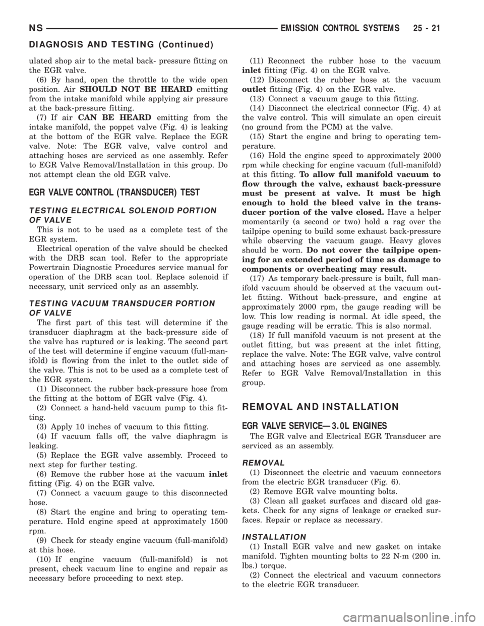
(1) Disconnect the rubber back-pressure hose from
the fitting at the bottom of EGR valve (Fig. 4).
(2) Connect a hand-held vacuum pump to this fit-
ting.
(3) Apply 10 inches of vacuum to this fitting.
(4) If vacuum falls off, the valve diaphragm is
leaking.
(5) Replace the EGR valve assembly. Proceed to
next step for further testing.
(6) Remove the rubber hose at the vacuuminlet
fitting (Fig. 4) on the EGR valve.
(7) Connect a vacuum gauge to this disconnected
hose.
(8) Start the engine and bring to operating tem-
perature. Hold engine speed at approximately 1500
rpm.
(9) Check for steady engine vacuum (full-manifold)
at this hose.
(10) If engine vacuum (full-manifold) is not
present, check vacuum line to engine and repair as
necessary before proceeding to next step.(11) Reconnect the rubber hose to the vacuum
inletfitting (Fig. 4) on the EGR valve.
(12) Disconnect the rubber hose at the vacuum
outletfitting (Fig. 4) on the EGR valve.
(13) Connect a vacuum gauge to this fitting.
(14) Disconnect the electrical connector (Fig. 4) at
the valve control. This will simulate an open circuit
(no ground from the PCM) at the valve.
(15) Start the engine and bring to operating tem-
perature.
(16) Hold the engine speed to approximately 2000
rpm while checking for engine vacuum (full-manifold)
at this fitting.To allow full manifold vacuum to
flow through the valve, exhaust back-pressure
must be present at valve. It must be high
enough to hold the bleed valve in the trans-
ducer portion of the valve closed.Have a helper
momentarily (a second or two) hold a rag over the
tailpipe opening to build some exhaust back-pressure
while observing the vacuum gauge. Heavy gloves
should be worn.Do not cover the tailpipe open-
ing for an extended period of time as damage to
components or overheating may result.
(17) As temporary back-pressure is built, full man-
ifold vacuum should be observed at the vacuum out-
let fitting. Without back-pressure, and engine at
approximately 2000 rpm, the gauge reading will be
low. This low reading is normal. At idle speed, the
gauge reading will be erratic. This is also normal.
(18) If full manifold vacuum is not present at the
outlet fitting, but was present at the inlet fitting,
replace the valve. Note: The EGR valve, valve control
and attaching hoses are serviced as one assembly.
Refer to EGR Valve Removal/Installation in this
group.
REMOVAL AND INSTALLATION
EGR VALVE SERVICEÐ3.0L ENGINES
The EGR valve and Electrical EGR Transducer are
serviced as an assembly.
REMOVAL
(1) Disconnect the electric and vacuum connectors
from the electric EGR transducer (Fig. 6).
(2) Remove EGR valve mounting bolts.
(3) Clean all gasket surfaces and discard old gas-
kets. Check for any signs of leakage or cracked sur-
faces. Repair or replace as necessary.
INSTALLATION
(1) Install EGR valve and new gasket on intake
manifold. Tighten mounting bolts to 22 N´m (200 in.
lbs.) torque.
(2) Connect the electrical and vacuum connectors
to the electric EGR transducer.
NSEMISSION CONTROL SYSTEMS 25 - 21
DIAGNOSIS AND TESTING (Continued)