1996 CHRYSLER VOYAGER Heater hoses
[x] Cancel search: Heater hosesPage 1158 of 1938
²Non±isolatedcylinder head cover to 12 N´m
(105 in. lbs.).
²Isolatedcylinder head cover to 10 N´m (90 in.
lbs.) (Fig. 32).
(4) Connect PCV hose from cylinder head cover.
(5) Install intake manifold upper plenum. Refer to
Group 11, Exhaust System and Intake Manifold for
procedure.
(6) Install Wiper Unit. Refer to Group 8K, Wind-
shield Wipers and Washers for procedure.
(7) Connect negative cable to battery.
CYLINDER HEAD
REMOVAL
(1) Drain cooling system. Refer to Group 7, Cooling
System for procedure and disconnect negative cable
from battery.
(2) Remove upper and lower intake manifolds.
Refer to Group 11, Exhaust System and Intake Man-
ifold.
WARNING: INTAKE MANIFOLD GASKET IS MADE
OF VERY THIN METAL AND MAY CAUSE PER-
SONAL INJURY, HANDLE WITH CARE.
(3) Disconnect coil wires, sending unit wire, heater
hoses and bypass hose.
(4) Remove PCV system hoses, evaporation control
system hose and cylinder head covers.
(5) Remove exhaust manifolds.
(6) Remove rocker arm and shaft assemblies.
Remove push rods andmark positions to ensure
installation in original locations.
(7) Remove the 9 head bolts from each cylinder
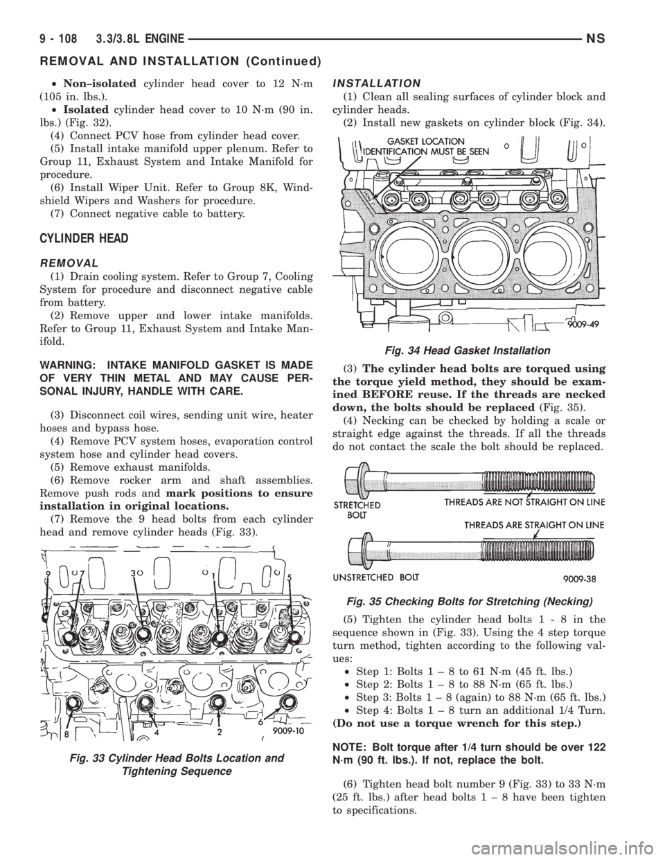
head and remove cylinder heads (Fig. 33).
INSTALLATION
(1) Clean all sealing surfaces of cylinder block and
cylinder heads.
(2) Install new gaskets on cylinder block (Fig. 34).
(3)The cylinder head bolts are torqued using
the torque yield method, they should be exam-
ined BEFORE reuse. If the threads are necked
down, the bolts should be replaced(Fig. 35).
(4) Necking can be checked by holding a scale or
straight edge against the threads. If all the threads
do not contact the scale the bolt should be replaced.
(5) Tighten the cylinder head bolts1-8inthe
sequence shown in (Fig. 33). Using the 4 step torque
turn method, tighten according to the following val-
ues:
²Step 1: Bolts1±8to61N´m(45ft.lbs.)
²Step 2: Bolts1±8to88N´m(65ft.lbs.)
²Step 3: Bolts1±8(again) to 88 N´m (65 ft. lbs.)
²Step 4: Bolts1±8turn an additional 1/4 Turn.
(Do not use a torque wrench for this step.)
NOTE: Bolt torque after 1/4 turn should be over 122
N´m (90 ft. lbs.). If not, replace the bolt.
(6) Tighten head bolt number 9 (Fig. 33) to 33 N´m
(25 ft. lbs.) after head bolts1±8have been tighten
to specifications.
Fig. 33 Cylinder Head Bolts Location and
Tightening Sequence
Fig. 34 Head Gasket Installation
Fig. 35 Checking Bolts for Stretching (Necking)
9 - 108 3.3/3.8L ENGINENS
REMOVAL AND INSTALLATION (Continued)
Page 1231 of 1938
ENGINE ASSEMBLY
REMOVAL
(1) Disconnect the battery.
(2) Remove the air cleaner assembly and inlet
hose.
(3) Remove both hoses at intercooler and engine.
(4) Disconnect EGR vacuum hose.
(5) Disconnect brake booster vacuum hose.
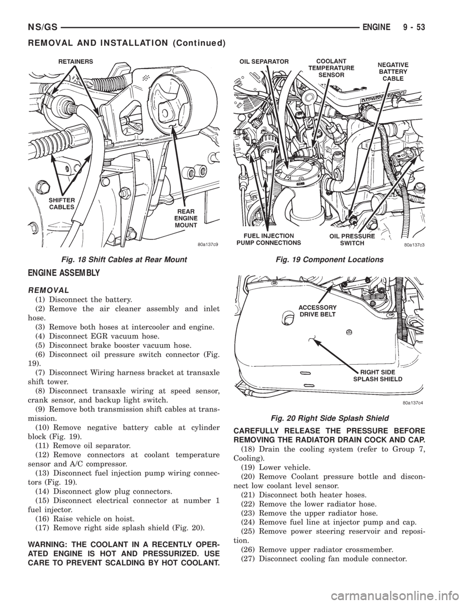
(6) Disconnect oil pressure switch connector (Fig.
19).
(7) Disconnect Wiring harness bracket at transaxle
shift tower.
(8) Disconnect transaxle wiring at speed sensor,
crank sensor, and backup light switch.
(9) Remove both transmission shift cables at trans-
mission.
(10) Remove negative battery cable at cylinder
block (Fig. 19).
(11) Remove oil separator.
(12) Remove connectors at coolant temperature
sensor and A/C compressor.
(13) Disconnect fuel injection pump wiring connec-
tors (Fig. 19).
(14) Disconnect glow plug connectors.
(15) Disconnect electrical connector at number 1
fuel injector.
(16) Raise vehicle on hoist.
(17) Remove right side splash shield (Fig. 20).
WARNING: THE COOLANT IN A RECENTLY OPER-
ATED ENGINE IS HOT AND PRESSURIZED. USE
CARE TO PREVENT SCALDING BY HOT COOLANT.CAREFULLY RELEASE THE PRESSURE BEFORE
REMOVING THE RADIATOR DRAIN COCK AND CAP.
(18) Drain the cooling system (refer to Group 7,
Cooling).
(19) Lower vehicle.
(20) Remove Coolant pressure bottle and discon-
nect low coolant level sensor.
(21) Disconnect both heater hoses.
(22) Remove the lower radiator hose.
(23) Remove the upper radiator hose.
(24) Remove fuel line at injector pump and cap.
(25) Remove power steering reservoir and reposi-
tion.
(26) Remove upper radiator crossmember.
(27) Disconnect cooling fan module connector.
Fig. 18 Shift Cables at Rear MountFig. 19 Component Locations
Fig. 20 Right Side Splash Shield
NS/GSENGINE 9 - 53
REMOVAL AND INSTALLATION (Continued)
Page 1233 of 1938
(3) Install cylinder head cover, torque nuts to 14.7
N´m (132 in. lbs.).
(4) Install coolant pressure tank.
(5) Install breather hose.
(6) Install generator bracket, tighten bolts to 7
N´m (4 ft. lbs.).
(7) Connect the service valves to the A/C compres-
sor ports, if equipped with air conditioning.
(8) Connect battery cable.
VALVE SPRINGSÐCYLINDER HEAD NOT
REMOVED
This procedure can be done with the engine cylin-
der head installed on the block.
REMOVAL
Each valve spring is held in place by a retainer
and a set of conical valve locks. The locks can be
removed only by compressing the valve spring.
(1) Remove the engine cylinder head cover, refer to
cylinder head cover removal in this section.
(2) Remove rocker arms assemblies for access to
each valve spring to be removed.
(3) Remove push rods. Retain the push rods, and
rocker arms assemblies in the same order and posi-
tion as removed.
(4) Inspect the springs and retainer for cracks and
possible signs of weakening.
(5) Install an air hose adaptor in the fuel injector
hole.
(6) Connect an air hose to the adapter and apply
air pressure slowly. Maintain at least 621 kPa (90psi) of air pressure in the cylinder to hold the valves
against their seats.
(7) Tap the retainer or tip with a rawhide hammer
to loosen the lock from the retainer. Use Valve Spring
Compressor Tool to compress the spring and remove
the locks.
(8) Remove valve spring and retainer.
Inspect the valve stems, especially the grooves. An
Arkansas smooth stone should be used to remove
nicks and high spots.
INSTALLATION
(1) Install valve spring and retainer.
(2) Compress the valve spring with Valve Spring
Compressor Tool and insert the valve locks. Release
the spring tension and remove the tool. Tap the
spring from side-to-side to ensure that the spring is
seated properly on the engine cylinder head.
(3) Disconnect the air hose. Remove the adaptor
from the fuel injector hole and install the fuel injec-
tor.
(4) Repeat the procedures for each remaining valve
spring to be removed.
(5) Install the push rods. Ensure the bottom end of
each rod is centered in the plunger cap seat of the
hydraulic valve tappet.
(6) Install the rocker arm assemblies, at their orig-
inal location.
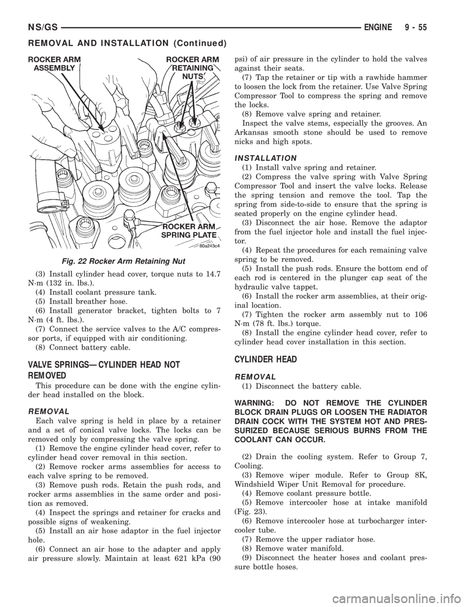
(7) Tighten the rocker arm assembly nut to 106
N´m (78 ft. lbs.) torque.
(8) Install the engine cylinder head cover, refer to
cylinder head cover installation in this section.
CYLINDER HEAD
REMOVAL
(1) Disconnect the battery cable.
WARNING: DO NOT REMOVE THE CYLINDER
BLOCK DRAIN PLUGS OR LOOSEN THE RADIATOR
DRAIN COCK WITH THE SYSTEM HOT AND PRES-
SURIZED BECAUSE SERIOUS BURNS FROM THE
COOLANT CAN OCCUR.
(2) Drain the cooling system. Refer to Group 7,
Cooling.
(3) Remove wiper module. Refer to Group 8K,
Windshield Wiper Unit Removal for procedure.
(4) Remove coolant pressure bottle.
(5) Remove intercooler hose at intake manifold
(Fig. 23).
(6) Remove intercooler hose at turbocharger inter-
cooler tube.
(7) Remove the upper radiator hose.
(8) Remove water manifold.
(9) Disconnect the heater hoses and coolant pres-
sure bottle hoses.
Fig. 22 Rocker Arm Retaining Nut
NS/GSENGINE 9 - 55
REMOVAL AND INSTALLATION (Continued)
Page 1269 of 1938
(5) Drain cooling system. Refer to Group 7, Cool-
ing System for procedure.
(6) Remove heater, and upper radiator hoses at
intake manifold.
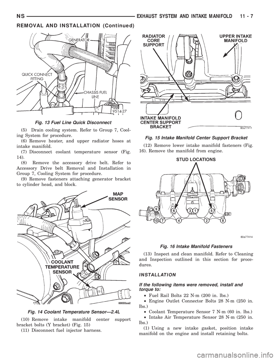
(7) Disconnect coolant temperature sensor (Fig.
14).
(8) Remove the accessory drive belt. Refer to
Accessory Drive belt Removal and Installation in
Group 7, Cooling System for procedure.
(9) Remove fasteners attaching generator bracket
to cylinder head, and block.
(10) Remove intake manifold center support
bracket bolts (Y bracket) (Fig. 15)
(11) Disconnect fuel injector harness.(12) Remove lower intake manifold fasteners (Fig.
16). Remove the manifold from engine.
(13) Inspect and clean manifold. Refer to Cleaning
and Inspection outlined in this section for proce-
dures.
INSTALLATION
If the following items were removed, install and
torque to:
²Fuel Rail Bolts 22 N´m (200 in. lbs.)
²Engine Outlet Connector Bolts 28 N´m (250 in.
lbs.)
²Coolant Temperature Sensor 7 N´m (60 in. lbs.)
²Intake Air Temperature Sensor 28 N´m (250 in.
lbs.)
(1) Using a new intake gasket, position intake
manifold on the engine and install retaining bolts.
Fig. 13 Fuel Line Quick Disconnect
Fig. 14 Coolant Temperature SensorÐ2.4L
Fig. 15 Intake Manifold Center Support Bracket
Fig. 16 Intake Manifold Fasteners
NSEXHAUST SYSTEM AND INTAKE MANIFOLD 11 - 7
REMOVAL AND INSTALLATION (Continued)
Page 1371 of 1938
FUEL DELIVERY SYSTEMÐ2.5L DIESEL ENGINE
INDEX
page page
DESCRIPTION AND OPERATION
FUEL DRAIN TUBES..................... 7
FUEL FILTER/WATER SEPARATOR.......... 4
FUEL GAUGE SENDING UNIT.............. 4
FUEL HEATER RELAY.................... 8
FUEL HEATER.......................... 8
FUEL INJECTION PUMP.................. 5
FUEL INJECTORS....................... 6
FUEL SHUTDOWN SOLENOID............. 5
FUEL SYSTEM PRESSURE WARNING....... 3
FUEL TANK MODULE.................... 4
FUEL TANK............................ 3
FUEL TUBES/LINES/HOSES AND CLAMPSÐ
LOW-PRESSURE TYPE................. 6
HIGH-PRESSURE FUEL LINES............. 7
INTRODUCTION........................ 3
QUICK-CONNECT FITTINGSÐLOW PRESSURE
TYPE............................... 7
WASTEGATE (TURBOCHARGER)........... 8
DIAGNOSIS AND TESTING
AIR IN FUEL SYSTEM................... 11
FUEL HEATER RELAY TEST.............. 12
FUEL INJECTION PUMP TEST............. 12
FUEL INJECTOR SENSOR TEST........... 12
FUEL INJECTOR TEST.................. 12
FUEL SHUTDOWN SOLENOID TEST........ 13
FUEL SUPPLY RESTRICTIONS............ 13GENERAL INFORMATION................. 9
HIGH-PRESSURE FUEL LINE LEAK TEST.... 14
VISUAL INSPECTION..................... 9
WASTEGATE (TURBOCHARGER).......... 14
SERVICE PROCEDURES
AIR BLEED PROCEDURES............... 14
FUEL INJECTION PUMP TIMING........... 15
REMOVAL AND INSTALLATION
ACCELERATOR PEDAL.................. 16
AIR CLEANER ELEMENT................. 16
FUEL DRAIN TUBES.................... 16
FUEL FILTER/WATER SEPARATOR......... 16
FUEL HEATER RELAY................... 17
FUEL HEATER......................... 17
FUEL INJECTION PUMP................. 19
FUEL INJECTORS...................... 22
FUEL LEVEL SENSOR................... 18
FUEL RESERVOIR MODULE.............. 25
FUEL SHUTDOWN SOLENOID............ 23
FUEL TANK........................... 23
HIGH-PRESSURE LINES................. 26
SPECIFICATIONS
FUEL INJECTOR FIRING SEQUENCE....... 27
FUEL SYSTEM PRESSURE............... 27
FUEL TANK CAPACITY.................. 27
IDLE SPEED.......................... 27
DESCRIPTION AND OPERATION
INTRODUCTION
This Fuel Delivery section will cover components
not controlled by the PCM. For components con-
trolled by the PCM, refer to the Fuel Injection Sys-
temÐ2.5L Diesel Engine section of this group.
The fuel heater relay, fuel heater and fuel gauge
are not operated by the PCM. These components are
controlled by the ignition (key) switch. All other fuel
system electrical components necessary to operate
the engine are controlled or regulated by the PCM.
FUEL SYSTEM PRESSURE WARNING
WARNING: HIGH±PRESSURE FUEL LINES DELIVER
DIESEL FUEL UNDER EXTREME PRESSURE FROM
THE INJECTION PUMP TO THE FUEL INJECTORS.
THIS MAY BE AS HIGH AS 45,000 KPA (6526 PSI).
USE EXTREME CAUTION WHEN INSPECTING FORHIGH±PRESSURE FUEL LEAKS. INSPECT FOR
HIGH±PRESSURE FUEL LEAKS WITH A SHEET OF
CARDBOARD (Fig. 1). HIGH FUEL INJECTION
PRESSURE CAN CAUSE PERSONAL INJURY IF
CONTACT IS MADE WITH THE SKIN.
FUEL TANK
The fuel tank and tank mounting used with the
diesel powered engine is the same as used with gas-
oline powered models, although the fuel tank module
is different.
The fuel tank contains the fuel tank module and
two rollover valves. Two fuel lines are routed to the
fuel tank module. One line is used for fuel supply to
the fuel filter/water separator. The other is used to
return excess fuel back to the fuel tank.
The fuel tank module contains the fuel gauge elec-
trical sending unit.An electrical fuel pump is not
used with the diesel engine.
NS/GSFUEL SYSTEMÐ2.5L DIESEL ENGINE/2.0L GAS ENGINE 14 - 3
Page 1377 of 1938
DIAGNOSIS AND TESTING
GENERAL INFORMATION
This section of the group will cover a general diag-
nosis of diesel engine fuel system components.
Diagnostic Trouble Codes:Refer to On-Board
Diagnostics in Group 25, Emission Control System
for a list of Diagnostic Trouble Codes (DTC's) for cer-
tain fuel system components.
The PCM must be tested with the DRBIII scan
tool. The DRBIII should be the first step in any diag-
nosis of engine performance complaints. Refer to the
1997 GS 2.5L Diesel Powertrain Diagnostic Proce-
dures manual for diagnosis and testing of the diesel
engine control system.
VISUAL INSPECTION
A visual inspection for loose, disconnected, or incor-
rectly routed wires and hoses should be made before
attempting to diagnose or service the diesel fuel
injection system. A visual check will help find these
conditions. It also saves unnecessary test and diag-
nostic time. A thorough visual inspection of the fuel
injection system includes the following checks:
(1) Be sure that the battery connections are tight
and not corroded.
(2) Be sure that the 68 way connector is fully
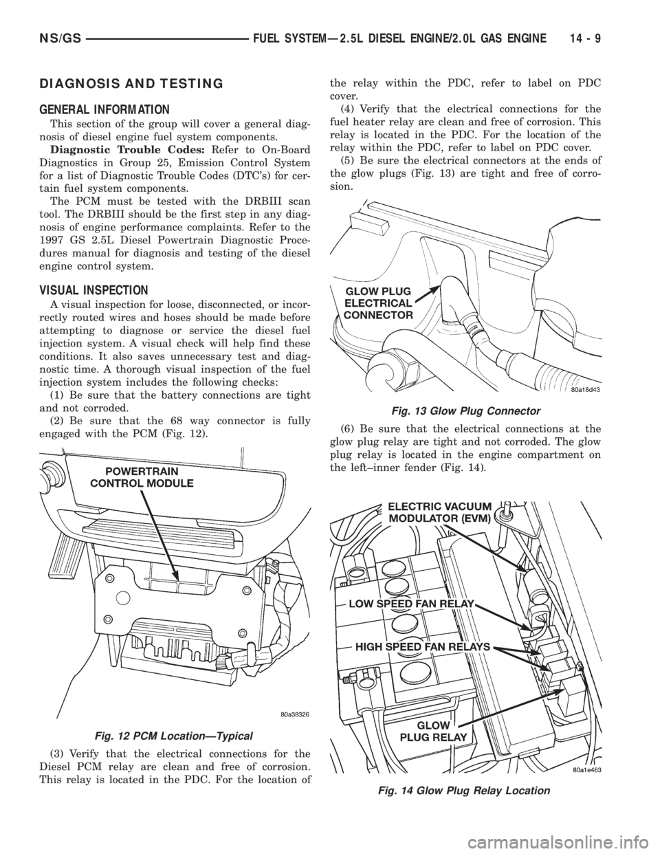
engaged with the PCM (Fig. 12).
(3) Verify that the electrical connections for the
Diesel PCM relay are clean and free of corrosion.
This relay is located in the PDC. For the location ofthe relay within the PDC, refer to label on PDC
cover.
(4) Verify that the electrical connections for the
fuel heater relay are clean and free of corrosion. This
relay is located in the PDC. For the location of the
relay within the PDC, refer to label on PDC cover.
(5) Be sure the electrical connectors at the ends of
the glow plugs (Fig. 13) are tight and free of corro-
sion.
(6) Be sure that the electrical connections at the
glow plug relay are tight and not corroded. The glow
plug relay is located in the engine compartment on
the left±inner fender (Fig. 14).
Fig. 12 PCM LocationÐTypical
Fig. 13 Glow Plug Connector
Fig. 14 Glow Plug Relay Location
NS/GSFUEL SYSTEMÐ2.5L DIESEL ENGINE/2.0L GAS ENGINE 14 - 9
Page 1384 of 1938
REMOVAL AND INSTALLATION
ACCELERATOR PEDAL
CAUTION: Be careful not to damage or kink the
cable core wire (within the cable sheathing) while
servicing the accelerator pedal or throttle cable.
REMOVAL
(1) Disconnect electrical connector.
(2) Remove accelerator pedal mounting bracket
nuts. Remove accelerator pedal assembly.
INSTALLATION
(1) Place accelerator pedal assembly over studs
protruding from floor pan. Tighten mounting nuts to
5 N´m (46 in. lbs.) torque.
(2) Connect electrical connector.
(3) Before starting the engine, operate the acceler-
ator pedal to check for any binding.
AIR CLEANER ELEMENT
REMOVAL
(1) Remove hose clamp at Mass Air Flow Sensor.
(2) Remove hose from Mass Air Flow Sensor.(3) Loosen 2 clamps holding air cleaner housing
halves together.
(4) Remove left side of air cleaner housing.
(5) Remove element from air cleaner housing.
INSTALLATION
(1) Install a new element in housing.
(2) Position left side of housing.
(3) Snap clamps into place.
(4) Install hoses and clamps.
FUEL DRAIN TUBES
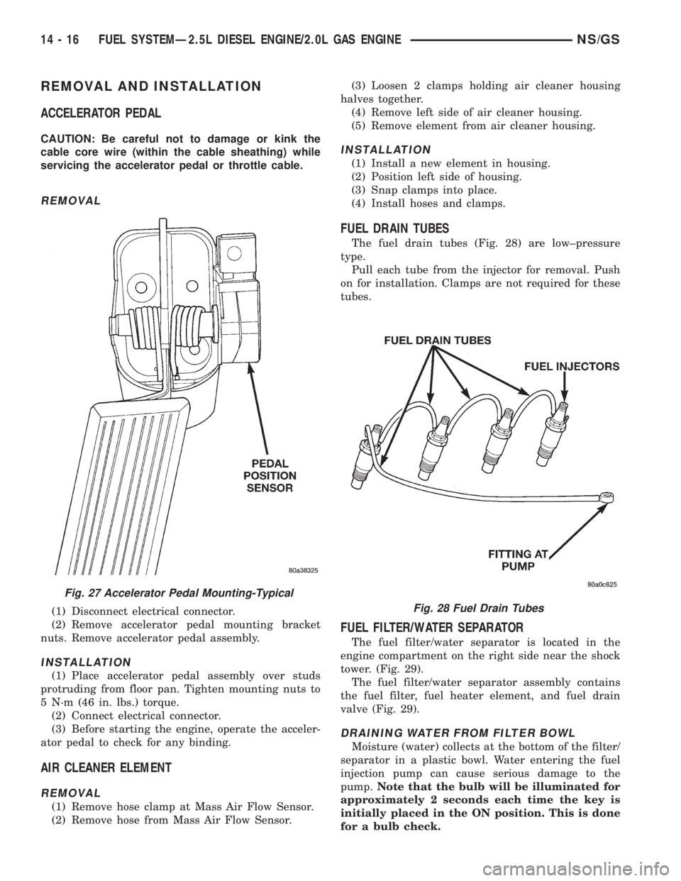
The fuel drain tubes (Fig. 28) are low±pressure
type.
Pull each tube from the injector for removal. Push
on for installation. Clamps are not required for these
tubes.
FUEL FILTER/WATER SEPARATOR
The fuel filter/water separator is located in the
engine compartment on the right side near the shock
tower. (Fig. 29).
The fuel filter/water separator assembly contains
the fuel filter, fuel heater element, and fuel drain
valve (Fig. 29).
DRAINING WATER FROM FILTER BOWL
Moisture (water) collects at the bottom of the filter/
separator in a plastic bowl. Water entering the fuel
injection pump can cause serious damage to the
pump.Note that the bulb will be illuminated for
approximately 2 seconds each time the key is
initially placed in the ON position. This is done
for a bulb check.
Fig. 27 Accelerator Pedal Mounting-Typical
Fig. 28 Fuel Drain Tubes
14 - 16 FUEL SYSTEMÐ2.5L DIESEL ENGINE/2.0L GAS ENGINENS/GS
Page 1817 of 1938
HEATING AND AIR CONDITIONING
CONTENTS
page page
FRONT HEATING AND AIR CONDITIONING
SYSTEM............................... 1REAR HEATING AND AIR CONDITIONING
SYSTEM.............................. 41
FRONT HEATING AND AIR CONDITIONING SYSTEM
INDEX
page page
GENERAL INFORMATION
INTRODUCTION......................... 2
SAFETY PRECAUTIONS AND WARNINGS...... 2
DESCRIPTION AND OPERATION
A/C PRESSURE TRANSDUCER.............. 2
A/C SERVICE PORTS..................... 2
AIR DISTRIBUTION DUCTS................. 2
COMPRESSOR HIGH-PRESSURE RELIEF
VALVE................................ 3
CONDENSATE DRAIN..................... 3
ENGINE COOLING SYSTEM REQUIREMENTS . . 3
EVAPORATOR PROBE..................... 3
HANDLING TUBING AND FITTINGS........... 3
HVAC CONTROL MODULE................. 4
REAR BLOWER SPEED SWITCH............ 3
SIDE DOOR HEATER A/C OUTLETS.......... 4
SIDE WINDOW DEMISTER................. 4
SYSTEM AIRFLOW....................... 4
SYSTEM OIL LEVEL...................... 5
DIAGNOSIS AND TESTING
A/C PERFORMANCE TEST................ 12
A/C PRESSURE TRANSDUCER............. 12
ACTUATOR CALIBRATION/DIAGNOSTICS AND
COOLDOWN TEST...................... 6
BLOWER MOTOR AND WHEEL ASSEMBLY.... 13
COMPRESSOR CLUTCH/COIL.............. 13
COMPRESSOR NOISE DIAGNOSIS.......... 13
EXPANSION VALVE...................... 13
HEATER PERFORMANCE TEST............ 15
HVAC CONTROL DIAGNOSTIC CONDITIONS . . . 9
SYSTEM CHARGE LEVEL TEST............ 16SERVICE PROCEDURES
CHARGING REFRIGERANT SYSTEM........ 17
EVACUATING REFRIGERANT SYSTEM....... 18
R-134a REFRIGERANT................... 16
STICKING HVAC CONTROL MODULE PUSH
BUTTONS............................ 19
SYSTEM LEAK CHECKING................ 19
THERMOCOUPLE PROBE................. 19
REMOVAL AND INSTALLATION
A/C PRESSURE TRANSDUCER............. 20
A/C SERVICE PORTS.................... 20
BLEND-AIR DOOR ACTUATOR............. 20
BLOWER MOTOR AND WHEEL ASSEMBLY.... 21
BLOWER MOTOR RESISTOR BLOCK........ 21
BLOWER MOTOR WHEEL................. 22
COMPRESSOR CLUTCH/COIL.............. 23
COMPRESSOR......................... 23
CONDENSER ASSEMBLY................. 25
DISCHARGE LINE....................... 26
EVAPORATOR PROBE.................... 27
EXPANSION VALVE...................... 28
FILTER-DRIER ASSEMBLY................. 28
HEATER A/C UNIT HOUSING............... 29
HEATER CORE......................... 30
HEATER HOSES........................ 31
LIQUID LINE........................... 32
MODE DOOR ACTUATOR................. 32
RECIRC DOOR ACTUATOR................ 34
SIDE WINDOW DEMISTER DUCTS.......... 33
SUCTION LINE.......................... 33
DISASSEMBLY AND ASSEMBLY
HEATER A/C UNIT RECONDITION........... 34
NSHEATING AND AIR CONDITIONING 24 - 1