1996 CHRYSLER VOYAGER wiring
[x] Cancel search: wiringPage 1315 of 1938
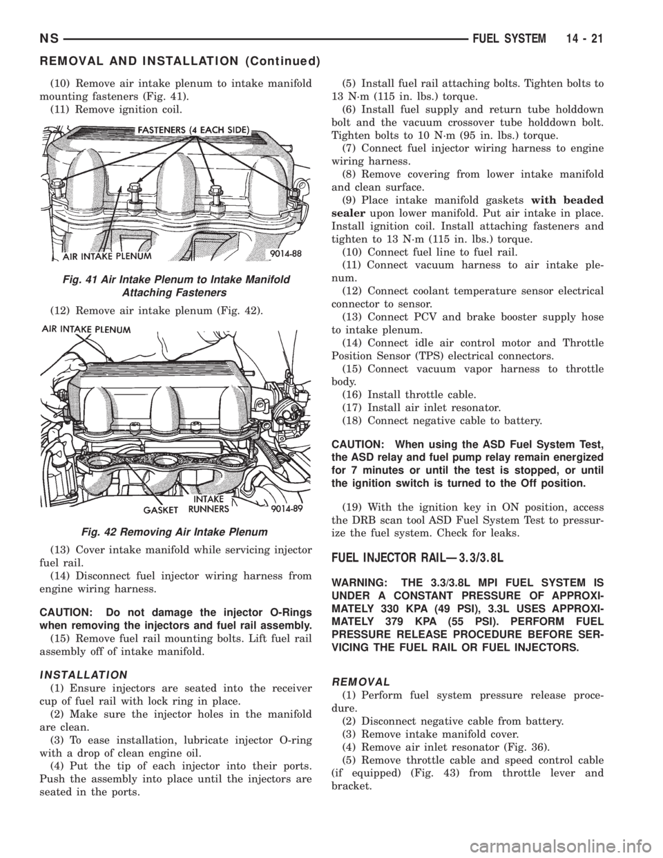
(10) Remove air intake plenum to intake manifold
mounting fasteners (Fig. 41).
(11) Remove ignition coil.
(12) Remove air intake plenum (Fig. 42).
(13) Cover intake manifold while servicing injector
fuel rail.
(14) Disconnect fuel injector wiring harness from
engine wiring harness.
CAUTION: Do not damage the injector O-Rings
when removing the injectors and fuel rail assembly.
(15) Remove fuel rail mounting bolts. Lift fuel rail
assembly off of intake manifold.
INSTALLATION
(1) Ensure injectors are seated into the receiver
cup of fuel rail with lock ring in place.
(2) Make sure the injector holes in the manifold
are clean.
(3) To ease installation, lubricate injector O-ring
with a drop of clean engine oil.
(4) Put the tip of each injector into their ports.
Push the assembly into place until the injectors are
seated in the ports.(5) Install fuel rail attaching bolts. Tighten bolts to
13 N´m (115 in. lbs.) torque.
(6) Install fuel supply and return tube holddown
bolt and the vacuum crossover tube holddown bolt.
Tighten bolts to 10 N´m (95 in. lbs.) torque.
(7) Connect fuel injector wiring harness to engine
wiring harness.
(8) Remove covering from lower intake manifold
and clean surface.
(9) Place intake manifold gasketswith beaded
sealerupon lower manifold. Put air intake in place.
Install ignition coil. Install attaching fasteners and
tighten to 13 N´m (115 in. lbs.) torque.
(10) Connect fuel line to fuel rail.
(11) Connect vacuum harness to air intake ple-
num.
(12) Connect coolant temperature sensor electrical
connector to sensor.
(13) Connect PCV and brake booster supply hose
to intake plenum.
(14) Connect idle air control motor and Throttle
Position Sensor (TPS) electrical connectors.
(15) Connect vacuum vapor harness to throttle
body.
(16) Install throttle cable.
(17) Install air inlet resonator.
(18) Connect negative cable to battery.
CAUTION: When using the ASD Fuel System Test,
the ASD relay and fuel pump relay remain energized
for 7 minutes or until the test is stopped, or until
the ignition switch is turned to the Off position.
(19) With the ignition key in ON position, access
the DRB scan tool ASD Fuel System Test to pressur-
ize the fuel system. Check for leaks.
FUEL INJECTOR RAILÐ3.3/3.8L
WARNING: THE 3.3/3.8L MPI FUEL SYSTEM IS
UNDER A CONSTANT PRESSURE OF APPROXI-
MATELY 330 KPA (49 PSI), 3.3L USES APPROXI-
MATELY 379 KPA (55 PSI). PERFORM FUEL
PRESSURE RELEASE PROCEDURE BEFORE SER-
VICING THE FUEL RAIL OR FUEL INJECTORS.
REMOVAL
(1) Perform fuel system pressure release proce-
dure.
(2) Disconnect negative cable from battery.
(3) Remove intake manifold cover.
(4) Remove air inlet resonator (Fig. 36).
(5) Remove throttle cable and speed control cable
(if equipped) (Fig. 43) from throttle lever and
bracket.
Fig. 41 Air Intake Plenum to Intake Manifold
Attaching Fasteners
Fig. 42 Removing Air Intake Plenum
NSFUEL SYSTEM 14 - 21
REMOVAL AND INSTALLATION (Continued)
Page 1318 of 1938
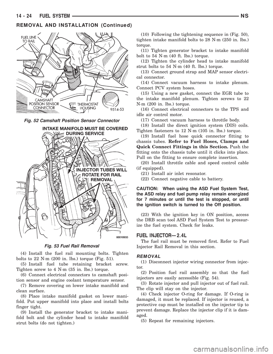
(4) Install the fuel rail mounting bolts. Tighten
bolts to 22 N´m (200 in. lbs.) torque (Fig. 51).
(5) Install fuel tube retaining bracket screw.
Tighten screw to 4 N´m (35 in. lbs.) torque.
(6) Connect electrical connectors to camshaft posi-
tion sensor and engine coolant temperature sensor.
(7) Remove covering on lower intake manifold and
clean surface.
(8) Place intake manifold gasket on lower mani-
fold. Put upper manifold into place and install bolts
finger tight.
(9) Install the generator bracket to intake mani-
fold bolt and the cylinder head to intake manifold
strut bolts (do not tighten.)(10) Following the tightening sequence in (Fig. 50),
tighten intake manifold bolts to 28 N´m (250 in. lbs.)
torque.
(11) Tighten generator bracket to intake manifold
bolt to 54 N´m (40 ft. lbs.) torque.
(12) Tighten the cylinder head to intake manifold
strut bolts to 54 N´m (40 ft. lbs.) torque.
(13) Connect ground strap and MAP sensor electri-
cal connector.
(14) Connect vacuum harness to intake plenum.
Connect PCV system hoses.
(15) Using a new gasket, connect the EGR tube to
the intake manifold plenum. Tighten screws to 22
N´m (200 in. lbs.) torque.
(16) Connect electrical connectors to the TPS and
idle air control motor.
(17) Connect vacuum harness to throttle body.
(18) Install the direct ignition system (DIS) coils.
Tighten fasteners to 12 N´m (105 in. lbs.) torque.
(19) Install fuel hose quick connector fitting to
chassis tubes.Refer to Fuel Hoses, Clamps and
Quick Connect Fittings in this Section.Push the
fitting onto the chassis tube until it clicks into place.
Pull on the fitting to ensure complete insertion.
(20) Install throttle cable and speed control cable
(if equipped).
(21) Install air inlet resonator.
(22) Connect negative cable to battery.
CAUTION: When using the ASD Fuel System Test,
the ASD relay and fuel pump relay remain energized
for 7 minutes or until the test is stopped, or until
the ignition switch is turned to the Off position.
(23) With the ignition key in ON position, access
the DRB scan tool ASD Fuel System Test to pressur-
ize the fuel system. Check for leaks.
FUEL INJECTORÐ2.4L
The fuel rail must be removed first. Refer to Fuel
Injector Rail Removal in this section.
REMOVAL
(1) Disconnect injector wiring connector from injec-
tor.
(2) Position fuel rail assembly so that the fuel
injectors are easily accessible (Fig. 54).
(3) Rotate injector and pull injector out of fuel rail.
The clip will stay on the injector.
(4) Check injector O-ring for damage. If O-ring is
damaged, it must be replaced. If injector is reused, a
protective cap must be installed on the injector tip to
prevent damage. Replace the injector clip if it is dam-
aged.
(5) Repeat for remaining injectors.
Fig. 52 Camshaft Position Sensor Connector
Fig. 53 Fuel Rail Removal
14 - 24 FUEL SYSTEMNS
REMOVAL AND INSTALLATION (Continued)
Page 1319 of 1938
INSTALLATION
(1) Before installing an injector the rubber O-ring
must be lubricated with a drop of clean engine oil to
aid in installation.
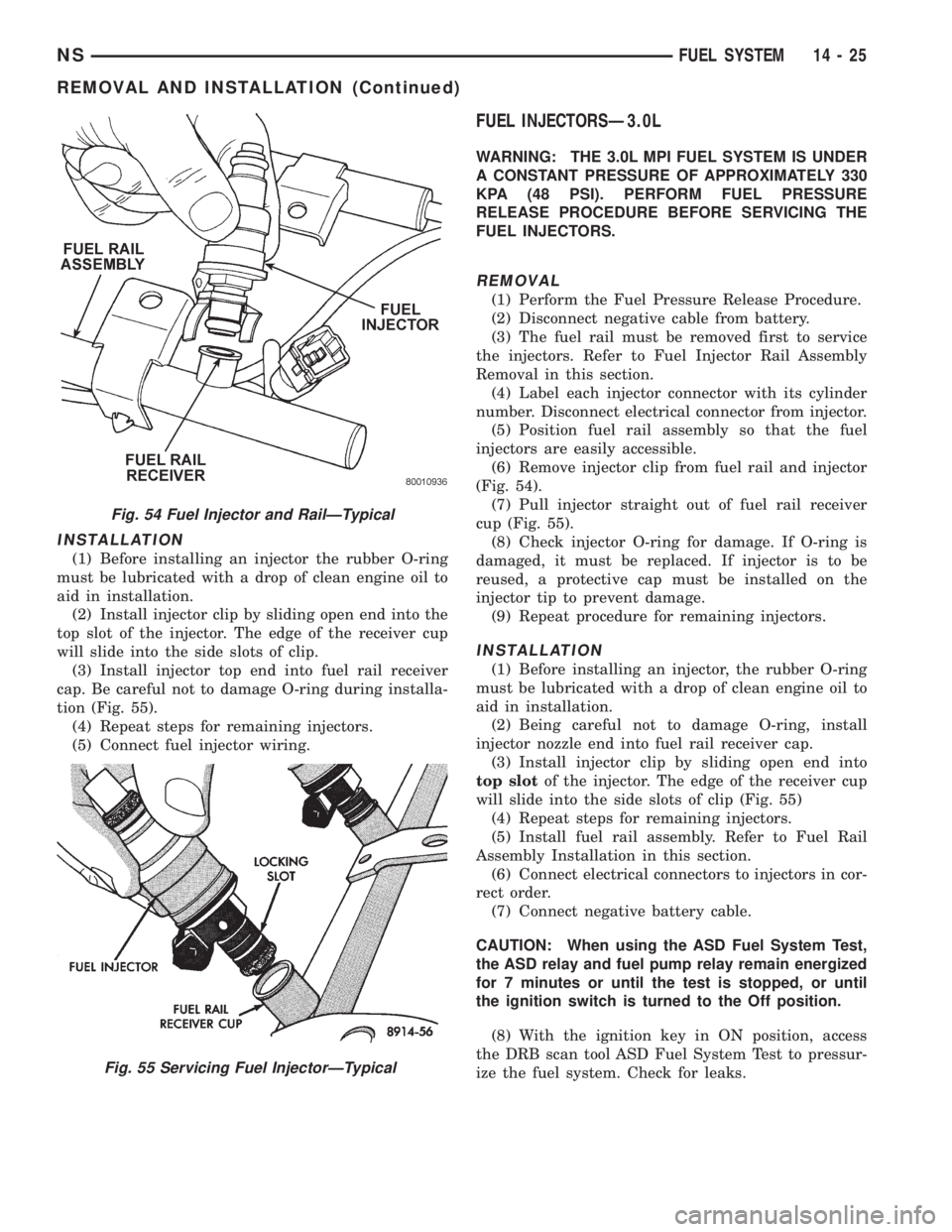
(2) Install injector clip by sliding open end into the
top slot of the injector. The edge of the receiver cup
will slide into the side slots of clip.
(3) Install injector top end into fuel rail receiver
cap. Be careful not to damage O-ring during installa-
tion (Fig. 55).
(4) Repeat steps for remaining injectors.
(5) Connect fuel injector wiring.
FUEL INJECTORSÐ3.0L
WARNING: THE 3.0L MPI FUEL SYSTEM IS UNDER
A CONSTANT PRESSURE OF APPROXIMATELY 330
KPA (48 PSI). PERFORM FUEL PRESSURE
RELEASE PROCEDURE BEFORE SERVICING THE
FUEL INJECTORS.
REMOVAL
(1) Perform the Fuel Pressure Release Procedure.
(2) Disconnect negative cable from battery.
(3) The fuel rail must be removed first to service
the injectors. Refer to Fuel Injector Rail Assembly
Removal in this section.
(4) Label each injector connector with its cylinder
number. Disconnect electrical connector from injector.
(5) Position fuel rail assembly so that the fuel
injectors are easily accessible.
(6) Remove injector clip from fuel rail and injector
(Fig. 54).
(7) Pull injector straight out of fuel rail receiver
cup (Fig. 55).
(8) Check injector O-ring for damage. If O-ring is
damaged, it must be replaced. If injector is to be
reused, a protective cap must be installed on the
injector tip to prevent damage.
(9) Repeat procedure for remaining injectors.
INSTALLATION
(1) Before installing an injector, the rubber O-ring
must be lubricated with a drop of clean engine oil to
aid in installation.
(2) Being careful not to damage O-ring, install
injector nozzle end into fuel rail receiver cap.
(3) Install injector clip by sliding open end into
top slotof the injector. The edge of the receiver cup
will slide into the side slots of clip (Fig. 55)
(4) Repeat steps for remaining injectors.
(5) Install fuel rail assembly. Refer to Fuel Rail
Assembly Installation in this section.
(6) Connect electrical connectors to injectors in cor-
rect order.
(7) Connect negative battery cable.
CAUTION: When using the ASD Fuel System Test,
the ASD relay and fuel pump relay remain energized
for 7 minutes or until the test is stopped, or until
the ignition switch is turned to the Off position.
(8) With the ignition key in ON position, access
the DRB scan tool ASD Fuel System Test to pressur-
ize the fuel system. Check for leaks.
Fig. 54 Fuel Injector and RailÐTypical
Fig. 55 Servicing Fuel InjectorÐTypical
NSFUEL SYSTEM 14 - 25
REMOVAL AND INSTALLATION (Continued)
Page 1320 of 1938
FUEL INJECTORÐ3.3/3.8L
The fuel rail must be removed first. Refer to Fuel
Injector Rail Assembly Removal in this section.
REMOVAL
(1) Disconnect injector wiring connector from injec-
tor.
(2) Position fuel rail assembly so that the fuel
injectors are easily accessible (Fig. 54).
(3) Rotate injector and pull injector out of fuel rail.
The clip will stay on the injector.
(4) Check injector O-ring for damage. If O-ring is
damaged, it must be replaced. If injector is reused, a
protective cap must be installed on the injector tip to
prevent damage. Replace the injector clip if it is dam-
aged.
(5) Repeat for remaining injectors.
INSTALLATION
(1) Before installing an injector the rubber O-ring
must be lubricated with a drop of clean engine oil to
aid in installation.
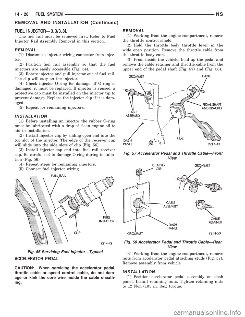
(2) Install injector clip by sliding open end into the
top slot of the injector. The edge of the receiver cup
will slide into the side slots of clip (Fig. 56).
(3) Install injector top end into fuel rail receiver
cap. Be careful not to damage O-ring during installa-
tion (Fig. 56).
(4) Repeat steps for remaining injectors.
(5) Connect fuel injector wiring.
ACCELERATOR PEDAL
CAUTION: When servicing the accelerator pedal,
throttle cable or speed control cable, do not dam-
age or kink the core wire inside the cable sheath-
ing.
REMOVAL
(1) Working from the engine compartment, remove
the throttle control shield.
(2) Hold the throttle body throttle lever in the
wide open position. Remove the throttle cable from
the throttle body cam.
(3) From inside the vehicle, hold up the pedal and
remove the cable retainer and throttle cable from the
upper end of the pedal shaft (Fig. 57) and (Fig. 58).
(4) Working from the engine compartment, remove
nuts from accelerator pedal attaching studs (Fig. 57).
Remove assembly from vehicle.
INSTALLATION
(1) Position accelerator pedal assembly on dash
panel. Install retaining nuts. Tighten retaining nuts
to 12 N´m (105 in. lbs.) torque.
Fig. 56 Servicing Fuel InjectorÐTypical
Fig. 57 Accelerator Pedal and Throttle CableÐFront
View
Fig. 58 Accelerator Pedal and Throttle CableÐRear
View
14 - 26 FUEL SYSTEMNS
REMOVAL AND INSTALLATION (Continued)
Page 1336 of 1938

in the engine compartment next to the battery (Fig.
30). A label affixed to the underside of the PDC cover
identifies the relays and fuses in the PDC.
GENERATOR FIELDÐPCM OUTPUT
The PCM regulates the charging system voltage
within a range of 12.9 to 15.0 volts. Refer to Group
8A for Battery system information and 8C for charg-
ing system information.
AUTOMATIC SHUTDOWN RELAYÐPCM OUTPUT
The Automatic Shutdown (ASD) relay supplies bat-
tery voltage to the fuel injectors, electronic ignition
coil and the heating elements in the oxygen sensors.
A buss bar in the Power Distribution Center (PDC)
supplies voltage to the solenoid side and contact side
of the relay. The ASD relay power circuit contains a
25 amp fuse between the buss bar in the PDC and
the relay. The fuse is located in the PDC. Refer to
Group 8W, Wiring Diagrams for circuit information.
The PCM controls the relay by switching the
ground path for the solenoid side of the relay on and
off. The PCM turns the ground path off when the
ignition switch is in the Off position unless the 02
Heater Monitor test is being run. Refer to Group 25,
On-Board Diagnostics. When the ignition switch is in
the On or Crank position, the PCM monitors the
crankshaft position sensor and camshaft position sen-
sor signals to determine engine speed and ignition
timing (coil dwell). If the PCM does not receive the
crankshaft position sensor and camshaft position sen-
sor signals when the ignition switch is in the Run
position, it will de-energize the ASD relay.The ASD relay is located in the PDC (Fig. 30). A
label affixed to the underside of the PDC cover iden-
tifies the relays and fuses in the PDC.
FUEL PUMP RELAYÐPCM OUTPUT
The fuel pump relay supplies battery voltage to the
fuel pump. The fuel pump relay power circuit con-
tains a 9 amp fuse. The fuse is located in the PDC.
Refer to Group 8W, Wiring Diagrams for circuit infor-
mation.
The PCM controls the fuel pump relay by switch-
ing the ground path for the solenoid side of the relay
on and off. The PCM turns the ground path off when
the ignition switch is in the Off position. When the
ignition switch is in the On position, the PCM ener-
gizes the fuel pump. If the crankshaft position sensor
does not detect engine rotation, the PCM de-ener-
gizes the relay after approximately one second.
The fuel pump relay is located in the PDC (Fig.
30). A label affixed to the underside of the PDC cover
identifies the relays and fuses in the PDC.
STARTER RELAYÐPCM OUTPUT
Double Start Override ia a feature that prevents
the starter from operating if the engine is already
running. This feature is accomplished with software
only. There was no hardware added because of this
feature. To incorporate the unique feature of Double
Start Override, it was necessary to use the PCM
(software) to control the starter circuit. To use the
PCM it was necessary to separate the starter relay
coil ground from the park neutral switch. The starter
relay ground is now controlled through Pin 60 of the
PCM. This allows the PCM to interrupt the ground
circuit if other inputs tell it that the engine is turn-
ing. If the starter system is operating properly, it can
be assumed that the override protection is also work-
ing.
IDLE AIR CONTROL MOTORÐPCM OUTPUT
The idle air control motor is mounted on the throt-
tle body. The PCM operates the idle air control motor
(Fig. 26) or (Fig. 27) or (Fig. 28). The PCM adjusts
engine idle speed through the idle air control motor
to compensate for engine load or ambient conditions.
The throttle body has an air bypass passage that
provides air for the engine at idle (the throttle blade
is closed). The idle air control motor pintle protrudes
into the air bypass passage and regulates air flow
through it.
The PCM adjusts engine idle speed by moving the
idle air control motor pintle in and out of the bypass
passage. The adjustments are based on inputs the
PCM receives. The inputs are from the throttle posi-
tion sensor, crankshaft position sensor, coolant tem-
perature sensor, and various switch operations
Fig. 30 Power Distribution Center (PDC)
14 - 42 FUEL SYSTEMNS
DESCRIPTION AND OPERATION (Continued)
Page 1343 of 1938
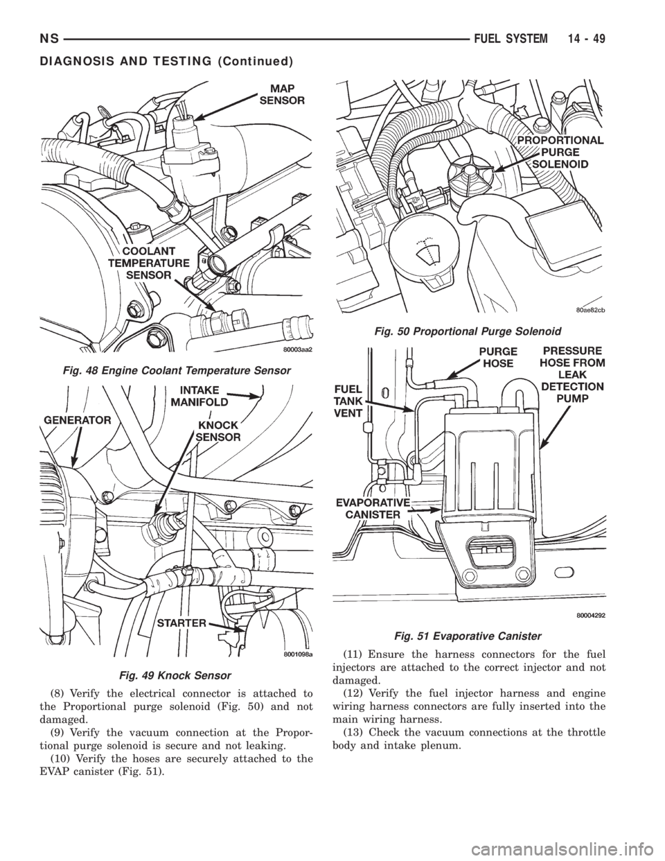
(8) Verify the electrical connector is attached to
the Proportional purge solenoid (Fig. 50) and not
damaged.
(9) Verify the vacuum connection at the Propor-
tional purge solenoid is secure and not leaking.
(10) Verify the hoses are securely attached to the
EVAP canister (Fig. 51).(11) Ensure the harness connectors for the fuel
injectors are attached to the correct injector and not
damaged.
(12) Verify the fuel injector harness and engine
wiring harness connectors are fully inserted into the
main wiring harness.
(13) Check the vacuum connections at the throttle
body and intake plenum.
Fig. 48 Engine Coolant Temperature Sensor
Fig. 49 Knock Sensor
Fig. 50 Proportional Purge Solenoid
Fig. 51 Evaporative Canister
NSFUEL SYSTEM 14 - 49
DIAGNOSIS AND TESTING (Continued)
Page 1344 of 1938
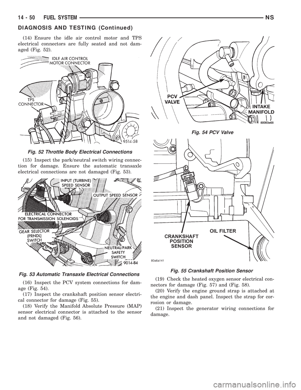
(14) Ensure the idle air control motor and TPS
electrical connectors are fully seated and not dam-
aged (Fig. 52).
(15) Inspect the park/neutral switch wiring connec-
tion for damage. Ensure the automatic transaxle
electrical connections are not damaged (Fig. 53).
(16) Inspect the PCV system connections for dam-
age (Fig. 54).
(17) Inspect the crankshaft position sensor electri-
cal connector for damage (Fig. 55).
(18) Verify the Manifold Absolute Pressure (MAP)
sensor electrical connector is attached to the sensor
and not damaged (Fig. 56).(19) Check the heated oxygen sensor electrical con-
nectors for damage (Fig. 57) and (Fig. 58).
(20) Verify the engine ground strap is attached at
the engine and dash panel. Inspect the strap for cor-
rosion or damage.
(21) Inspect the generator wiring connections for
damage.
Fig. 52 Throttle Body Electrical Connections
Fig. 53 Automatic Transaxle Electrical Connections
Fig. 54 PCV Valve
Fig. 55 Crankshaft Position Sensor
14 - 50 FUEL SYSTEMNS
DIAGNOSIS AND TESTING (Continued)
Page 1345 of 1938
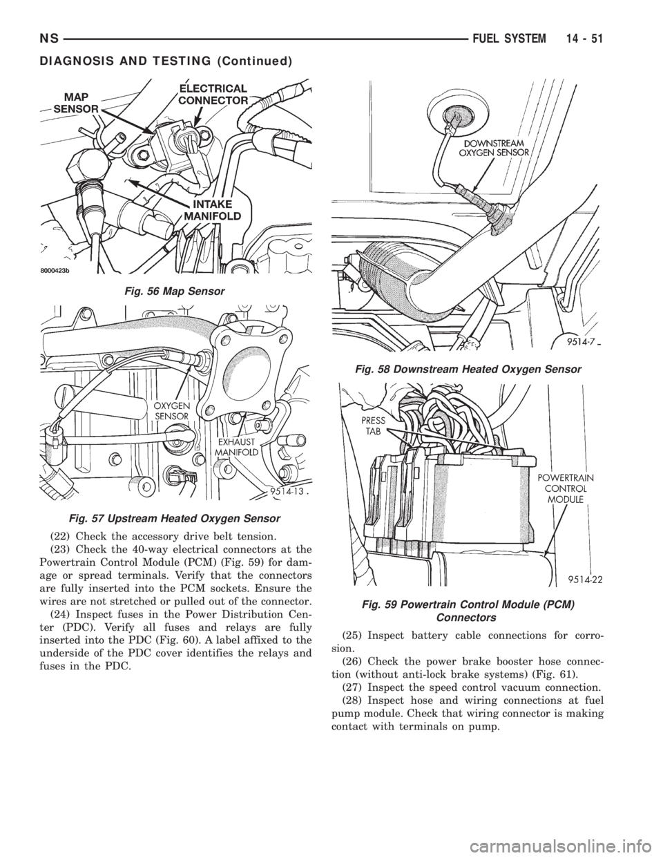
(22) Check the accessory drive belt tension.
(23) Check the 40-way electrical connectors at the
Powertrain Control Module (PCM) (Fig. 59) for dam-
age or spread terminals. Verify that the connectors
are fully inserted into the PCM sockets. Ensure the
wires are not stretched or pulled out of the connector.
(24) Inspect fuses in the Power Distribution Cen-
ter (PDC). Verify all fuses and relays are fully
inserted into the PDC (Fig. 60). A label affixed to the
underside of the PDC cover identifies the relays and
fuses in the PDC.(25) Inspect battery cable connections for corro-
sion.
(26) Check the power brake booster hose connec-
tion (without anti-lock brake systems) (Fig. 61).
(27) Inspect the speed control vacuum connection.
(28) Inspect hose and wiring connections at fuel
pump module. Check that wiring connector is making
contact with terminals on pump.
Fig. 56 Map Sensor
Fig. 57 Upstream Heated Oxygen Sensor
Fig. 58 Downstream Heated Oxygen Sensor
Fig. 59 Powertrain Control Module (PCM)
Connectors
NSFUEL SYSTEM 14 - 51
DIAGNOSIS AND TESTING (Continued)