1996 CHRYSLER VOYAGER brake sensor
[x] Cancel search: brake sensorPage 1085 of 1938
(4) Install cylinder head cover using procedure out-
lined in this section.
(5) Install rear timing belt cover and timing belt
idler pulley.
(6) Install timing belt and camshaft sprocket.
Refer to procedure outlined in this section.
(7) Install cam sensor and fuel injectors wiring
connectors.
(8) Install coil pack and plug wires onto the
engine. Connect coil pack wiring connector.
(9) Install power steering pump assembly.
(10) Raise vehicle and install the exhaust pipe to
the manifold.
(11) Install power brake vacuum hose to the intake
manifold.
(12) Install accessory drive belts. Refer to Group 7,
Cooling System for procedure.
(13) Install throttle linkage. Refer to Group 14,
Fuel System for procedures.
(14) Install air cleaner and connect all vacuum
lines, electrical wiring and fuel lines to the throttle
body.
(15) Fill cooling system. Refer to Group 7, Cooling
System for procedure. Connect negative battery
cable.
VALVES AND VALVE SPRINGS
REMOVAL
(1) With cylinder head removed, compress valve
springs using a universal valve spring compressor.
(2) Remove valve retaining locks, valve spring
retainers, valve stem seals and valve springs.(3) Before removing valves,remove any burrs
from valve stem lock grooves to prevent dam-
age to the valve guides.Identify valves to insure
installation in original location.
(4) Inspect and clean the valves. Refer to Cleaning
and Inspection outlined in this section for procedure.
INSTALLATION
(1) Coat valve stems with clean engine oil and
insert in cylinder head.
(2) Install new valve stem seals on all valves
using a valve stem seal tool (Fig. 51). The valve stem
seals should be pushed firmly and squarely over
valve guide.
CAUTION: When oversize valves are used, the cor-
responding oversize valve seal must also be used.
Excessive guide wear may result if oversize seals
are not used with oversize valves.
(3) Install valve springs and retainers. Compress
valve springs only enough to install locks, taking
care not to misalign the direction of compression.
Nicked valve stems may result from misalignment of
the valve spring compressor.
CAUTION: When depressing the valve spring
retainers with valve spring compressor the locks
can become dislocated. Ensure both locks are in
the correct location after removing tool.
(4) Check the valve spring installed height B after
refacing the valve and seat (Fig. 52). Make sure mea-
surements are taken from top of spring seat to the
bottom surface of spring retainer. If height is greater
than 38.75 mm (1.525 in.), install a .762 mm (0.030
in.) spacer under the valve spring seat to bring
spring height back within specification.
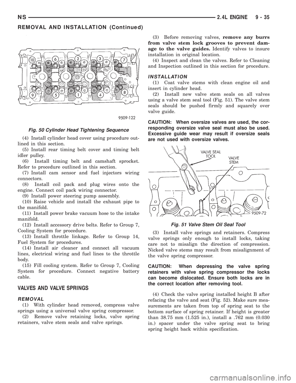
Fig. 50 Cylinder Head Tightening Sequence
Fig. 51 Valve Stem Oil Seal Tool
NS2.4L ENGINE 9 - 35
REMOVAL AND INSTALLATION (Continued)
Page 1188 of 1938
HYDRAULIC LASH ADJUSTER NOISE
A tappet-like noise may be produced from several
items. Refer to Lash Adjuster Noise - Diagnosis in
Standard Service Procedures, outlined in this Group.
Lash adjusters are replaced with the rocker
arm as an assembly.
VALVE SEALS AND SPRINGS IN VEHICLE
REMOVAL
(1) Remove rocker arm shafts assemblies as previ-
ously outlined in this section.
(2) Rotate crankshaft until piston is at TDC on
compression.
(3) With air hose attached to adapter tool installed
in spark plug hole, apply 90-120 psi air pressure.
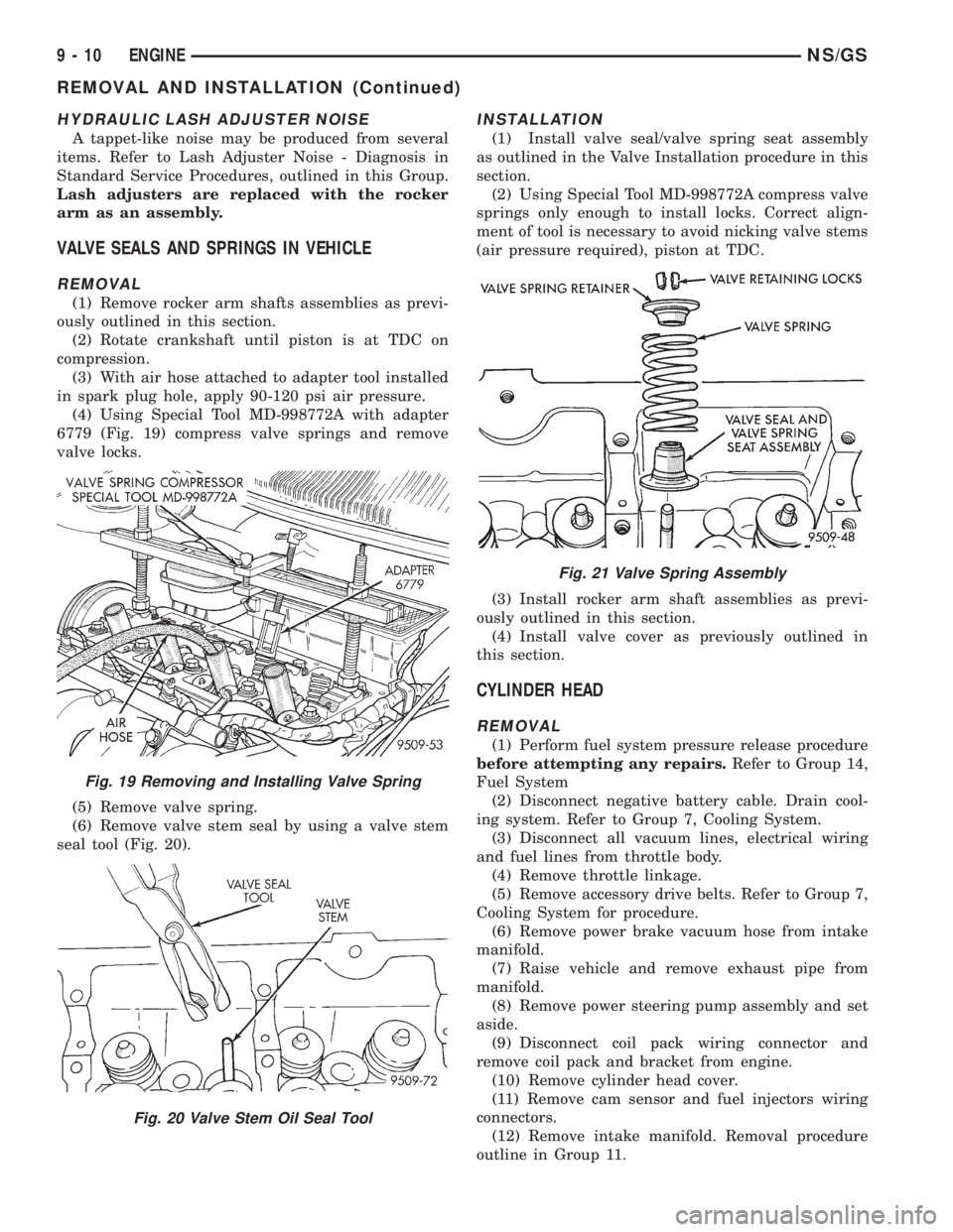
(4) Using Special Tool MD-998772A with adapter
6779 (Fig. 19) compress valve springs and remove
valve locks.
(5) Remove valve spring.
(6) Remove valve stem seal by using a valve stem
seal tool (Fig. 20).
INSTALLATION
(1) Install valve seal/valve spring seat assembly
as outlined in the Valve Installation procedure in this
section.
(2) Using Special Tool MD-998772A compress valve
springs only enough to install locks. Correct align-
ment of tool is necessary to avoid nicking valve stems
(air pressure required), piston at TDC.
(3) Install rocker arm shaft assemblies as previ-
ously outlined in this section.
(4) Install valve cover as previously outlined in
this section.
CYLINDER HEAD
REMOVAL
(1) Perform fuel system pressure release procedure
before attempting any repairs.Refer to Group 14,
Fuel System
(2) Disconnect negative battery cable. Drain cool-
ing system. Refer to Group 7, Cooling System.
(3) Disconnect all vacuum lines, electrical wiring
and fuel lines from throttle body.
(4) Remove throttle linkage.
(5) Remove accessory drive belts. Refer to Group 7,
Cooling System for procedure.
(6) Remove power brake vacuum hose from intake
manifold.
(7) Raise vehicle and remove exhaust pipe from
manifold.
(8) Remove power steering pump assembly and set
aside.
(9) Disconnect coil pack wiring connector and
remove coil pack and bracket from engine.
(10) Remove cylinder head cover.
(11) Remove cam sensor and fuel injectors wiring
connectors.
(12) Remove intake manifold. Removal procedure
outline in Group 11.
Fig. 19 Removing and Installing Valve Spring
Fig. 20 Valve Stem Oil Seal Tool
Fig. 21 Valve Spring Assembly
9 - 10 ENGINENS/GS
REMOVAL AND INSTALLATION (Continued)
Page 1231 of 1938
ENGINE ASSEMBLY
REMOVAL
(1) Disconnect the battery.
(2) Remove the air cleaner assembly and inlet
hose.
(3) Remove both hoses at intercooler and engine.
(4) Disconnect EGR vacuum hose.
(5) Disconnect brake booster vacuum hose.
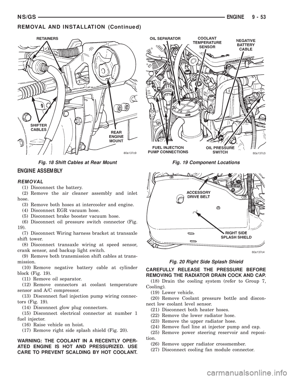
(6) Disconnect oil pressure switch connector (Fig.
19).
(7) Disconnect Wiring harness bracket at transaxle
shift tower.
(8) Disconnect transaxle wiring at speed sensor,
crank sensor, and backup light switch.
(9) Remove both transmission shift cables at trans-
mission.
(10) Remove negative battery cable at cylinder
block (Fig. 19).
(11) Remove oil separator.
(12) Remove connectors at coolant temperature
sensor and A/C compressor.
(13) Disconnect fuel injection pump wiring connec-
tors (Fig. 19).
(14) Disconnect glow plug connectors.
(15) Disconnect electrical connector at number 1
fuel injector.
(16) Raise vehicle on hoist.
(17) Remove right side splash shield (Fig. 20).
WARNING: THE COOLANT IN A RECENTLY OPER-
ATED ENGINE IS HOT AND PRESSURIZED. USE
CARE TO PREVENT SCALDING BY HOT COOLANT.CAREFULLY RELEASE THE PRESSURE BEFORE
REMOVING THE RADIATOR DRAIN COCK AND CAP.
(18) Drain the cooling system (refer to Group 7,
Cooling).
(19) Lower vehicle.
(20) Remove Coolant pressure bottle and discon-
nect low coolant level sensor.
(21) Disconnect both heater hoses.
(22) Remove the lower radiator hose.
(23) Remove the upper radiator hose.
(24) Remove fuel line at injector pump and cap.
(25) Remove power steering reservoir and reposi-
tion.
(26) Remove upper radiator crossmember.
(27) Disconnect cooling fan module connector.
Fig. 18 Shift Cables at Rear MountFig. 19 Component Locations
Fig. 20 Right Side Splash Shield
NS/GSENGINE 9 - 53
REMOVAL AND INSTALLATION (Continued)
Page 1268 of 1938
INSTALLATION
(1) Install new upper intake manifold gasket.
NOTE: Center outboard fastener is a double stud.
(2) Tighten upper intake manifold fasteners start-
ing at center and progressing outward in both direc-
tions. Tighten bolts to 28 N´m (250 in. lbs.). Repeat
this procedures until all fasteners are at specified
torque.
(3) Install dipstick tube. Seal tube to cylinder
block using MopartStud N' Bearing Mount Adhe-
sive. Tighten dipstick tube fastener to 12 N´m (105
in. lbs.)
(4) Install dipstick.
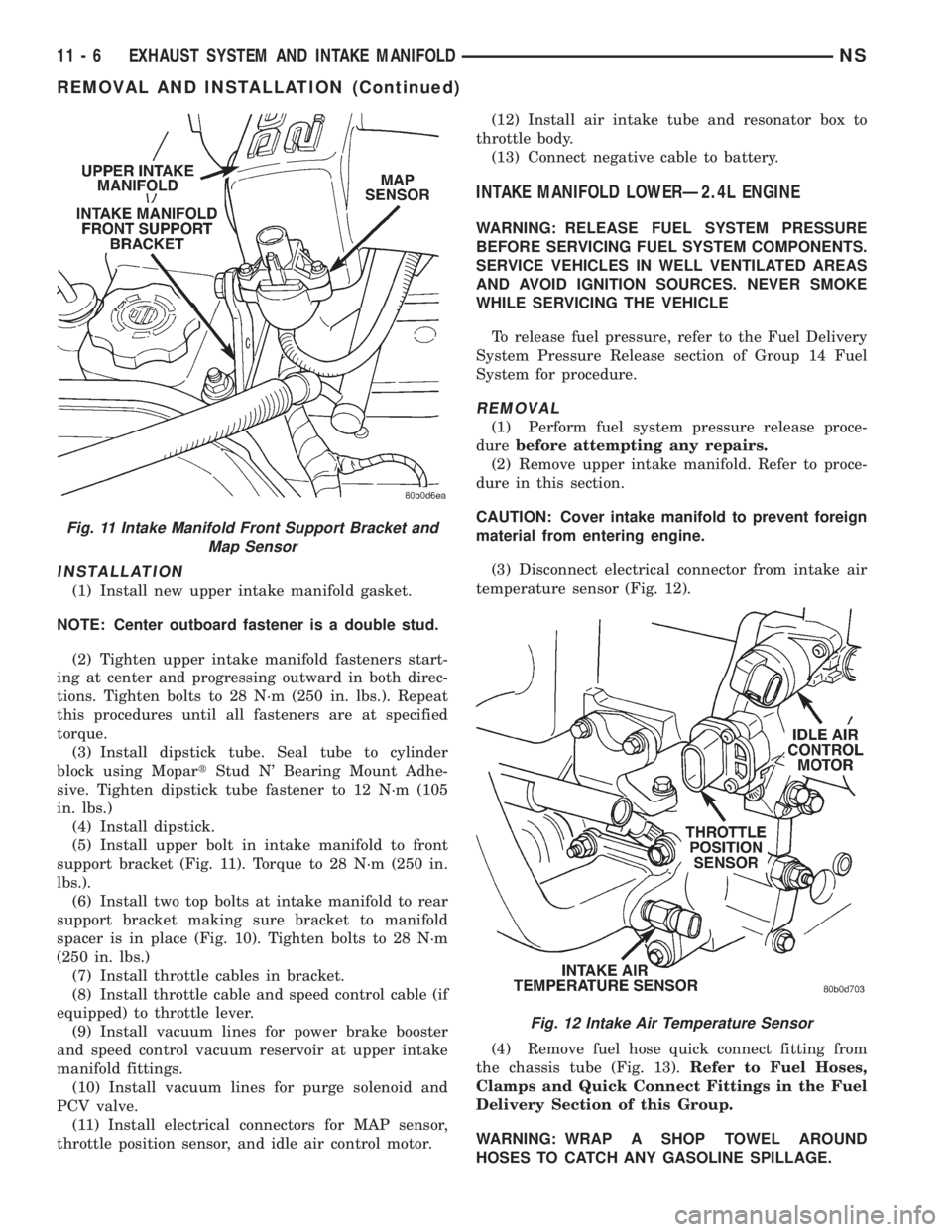
(5) Install upper bolt in intake manifold to front
support bracket (Fig. 11). Torque to 28 N´m (250 in.
lbs.).
(6) Install two top bolts at intake manifold to rear
support bracket making sure bracket to manifold
spacer is in place (Fig. 10). Tighten bolts to 28 N´m
(250 in. lbs.)
(7) Install throttle cables in bracket.
(8) Install throttle cable and speed control cable (if
equipped) to throttle lever.
(9) Install vacuum lines for power brake booster
and speed control vacuum reservoir at upper intake
manifold fittings.
(10) Install vacuum lines for purge solenoid and
PCV valve.
(11) Install electrical connectors for MAP sensor,
throttle position sensor, and idle air control motor.(12) Install air intake tube and resonator box to
throttle body.
(13) Connect negative cable to battery.
INTAKE MANIFOLD LOWERÐ2.4L ENGINE
WARNING: RELEASE FUEL SYSTEM PRESSURE
BEFORE SERVICING FUEL SYSTEM COMPONENTS.
SERVICE VEHICLES IN WELL VENTILATED AREAS
AND AVOID IGNITION SOURCES. NEVER SMOKE
WHILE SERVICING THE VEHICLE
To release fuel pressure, refer to the Fuel Delivery
System Pressure Release section of Group 14 Fuel
System for procedure.
REMOVAL
(1) Perform fuel system pressure release proce-
durebefore attempting any repairs.
(2) Remove upper intake manifold. Refer to proce-
dure in this section.
CAUTION: Cover intake manifold to prevent foreign
material from entering engine.
(3) Disconnect electrical connector from intake air
temperature sensor (Fig. 12).
(4) Remove fuel hose quick connect fitting from
the chassis tube (Fig. 13).Refer to Fuel Hoses,
Clamps and Quick Connect Fittings in the Fuel
Delivery Section of this Group.
WARNING: WRAP A SHOP TOWEL AROUND
HOSES TO CATCH ANY GASOLINE SPILLAGE.
Fig. 11 Intake Manifold Front Support Bracket and
Map Sensor
Fig. 12 Intake Air Temperature Sensor
11 - 6 EXHAUST SYSTEM AND INTAKE MANIFOLDNS
REMOVAL AND INSTALLATION (Continued)
Page 1270 of 1938
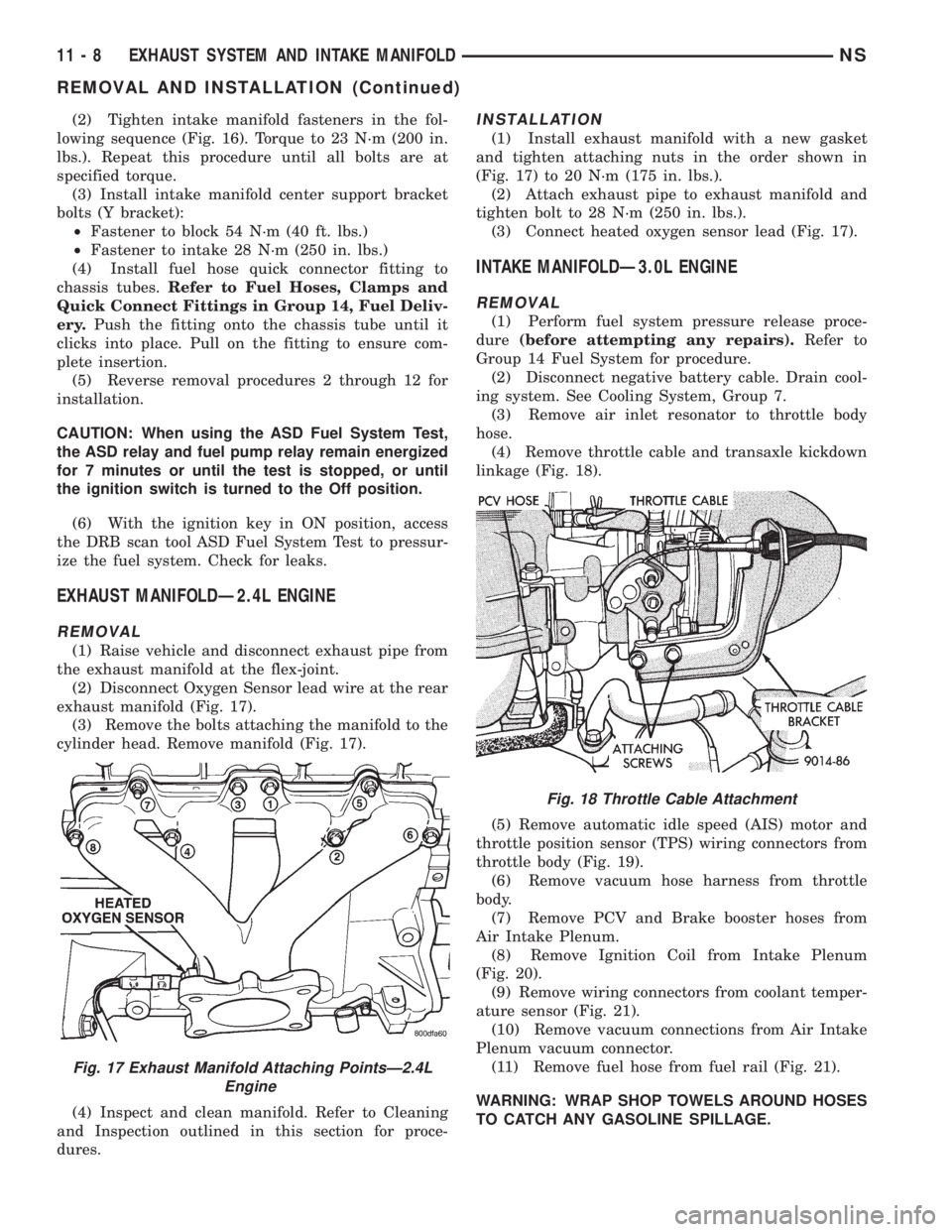
(2) Tighten intake manifold fasteners in the fol-
lowing sequence (Fig. 16). Torque to 23 N´m (200 in.
lbs.). Repeat this procedure until all bolts are at
specified torque.
(3) Install intake manifold center support bracket
bolts (Y bracket):
²Fastener to block 54 N´m (40 ft. lbs.)
²Fastener to intake 28 N´m (250 in. lbs.)
(4) Install fuel hose quick connector fitting to
chassis tubes.Refer to Fuel Hoses, Clamps and
Quick Connect Fittings in Group 14, Fuel Deliv-
ery.Push the fitting onto the chassis tube until it
clicks into place. Pull on the fitting to ensure com-
plete insertion.
(5) Reverse removal procedures 2 through 12 for
installation.
CAUTION: When using the ASD Fuel System Test,
the ASD relay and fuel pump relay remain energized
for 7 minutes or until the test is stopped, or until
the ignition switch is turned to the Off position.
(6) With the ignition key in ON position, access
the DRB scan tool ASD Fuel System Test to pressur-
ize the fuel system. Check for leaks.
EXHAUST MANIFOLDÐ2.4L ENGINE
REMOVAL
(1) Raise vehicle and disconnect exhaust pipe from
the exhaust manifold at the flex-joint.
(2) Disconnect Oxygen Sensor lead wire at the rear
exhaust manifold (Fig. 17).
(3) Remove the bolts attaching the manifold to the
cylinder head. Remove manifold (Fig. 17).
(4) Inspect and clean manifold. Refer to Cleaning
and Inspection outlined in this section for proce-
dures.
INSTALLATION
(1) Install exhaust manifold with a new gasket
and tighten attaching nuts in the order shown in
(Fig. 17) to 20 N´m (175 in. lbs.).
(2) Attach exhaust pipe to exhaust manifold and
tighten bolt to 28 N´m (250 in. lbs.).
(3) Connect heated oxygen sensor lead (Fig. 17).
INTAKE MANIFOLDÐ3.0L ENGINE
REMOVAL
(1) Perform fuel system pressure release proce-
dure(before attempting any repairs).Refer to
Group 14 Fuel System for procedure.
(2) Disconnect negative battery cable. Drain cool-
ing system. See Cooling System, Group 7.
(3) Remove air inlet resonator to throttle body
hose.
(4) Remove throttle cable and transaxle kickdown
linkage (Fig. 18).
(5) Remove automatic idle speed (AIS) motor and
throttle position sensor (TPS) wiring connectors from
throttle body (Fig. 19).
(6) Remove vacuum hose harness from throttle
body.
(7) Remove PCV and Brake booster hoses from
Air Intake Plenum.
(8) Remove Ignition Coil from Intake Plenum
(Fig. 20).
(9) Remove wiring connectors from coolant temper-
ature sensor (Fig. 21).
(10) Remove vacuum connections from Air Intake
Plenum vacuum connector.
(11) Remove fuel hose from fuel rail (Fig. 21).
WARNING: WRAP SHOP TOWELS AROUND HOSES
TO CATCH ANY GASOLINE SPILLAGE.
Fig. 17 Exhaust Manifold Attaching PointsÐ2.4L
Engine
Fig. 18 Throttle Cable Attachment
11 - 8 EXHAUST SYSTEM AND INTAKE MANIFOLDNS
REMOVAL AND INSTALLATION (Continued)
Page 1273 of 1938
(10) Connect fuel line to fuel rail (Fig. 21). Torque
hose clamps to 1 N´m (10 in. lbs.).
(11) Connect vacuum harness to air intake ple-
num.
(12) Connect and coolant temperature sensor elec-
trical connector to sensor (Fig. 21).
(13) Connect PCV and brake booster supply hose
to intake plenum.
(14) Connect automatic idle speed (AIS) motor
and throttle position sensor (TPS) electrical connec-
tors (Fig. 19).
(15) Connect vacuum vapor harness to throttle
body (Fig. 19).
(16) Install throttle cable and transaxle kickdown
linkage (Fig. 18).
(17) Install air inlet resonator hose assembly to
throttle body.
(18) Install radiator to thermostat housing hose
and heater hose to heater pipe nipple.
(19) Fill cooling system. Refer to Filling the Cool-
ing System outlined in Group 7 Cooling System for
procedure.
(20) Connect negative battery cable.
(21) With the DRB Scan Tool use ASD Fuel Sys-
tem Test to pressurize system to check for leaks.
CAUTION: When using the ASD Fuel System Test,
The Auto Shutdown (ASD) Relay will remain ener-
gized for 7 minutes or until the ignition switch is
turned to the OFF position, or Stop All Test is
selected.
EXHAUST MANIFOLDÐ3.0L ENGINE
REMOVAL
(1) Raise vehicle and disconnect exhaust pipe
from rear (cowl side) exhaust manifold at the flex-
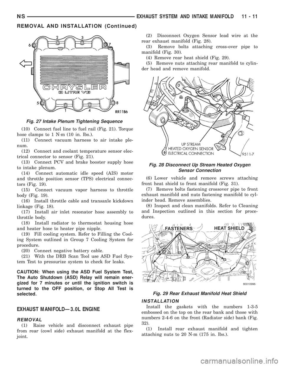
joint.(2) Disconnect Oxygen Sensor lead wire at the
rear exhaust manifold (Fig. 28).
(3) Remove bolts attaching cross-over pipe to
manifold (Fig. 30).
(4) Remove rear heat shield (Fig. 29).
(5) Remove nuts attaching rear manifold to cylin-
der head and remove manifold.
(6) Lower vehicle and remove screws attaching
front heat shield to front manifold (Fig. 31).
(7) Remove bolts fastening crossover pipe to front
exhaust manifold and nuts fastening manifold to cyl-
inder head. Remove assemblies.
(8) Inspect and clean manifolds. Refer to Cleaning
and Inspection outlined in this section for proce-
dures.
INSTALLATION
Install the gaskets with the numbers 1-3-5
embossed on the top on the rear bank and those with
numbers 2-4-6 on the front (Radiator side) bank (Fig.
32).
(1) Install rear exhaust manifold and tighten
attaching nuts to 20 N´m (175 in. lbs.).
Fig. 27 Intake Plenum Tightening Sequence
Fig. 28 Disconnect Up Stream Heated Oxygen
Sensor Connection
Fig. 29 Rear Exhaust Manifold Heat Shield
NSEXHAUST SYSTEM AND INTAKE MANIFOLD 11 - 11
REMOVAL AND INSTALLATION (Continued)
Page 1274 of 1938
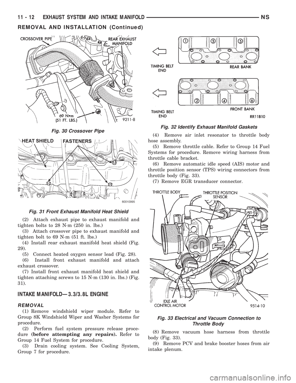
(2) Attach exhaust pipe to exhaust manifold and
tighten bolts to 28 N´m (250 in. lbs.)
(3) Attach crossover pipe to exhaust manifold and
tighten bolt to 69 N´m (51 ft. lbs.)
(4) Install rear exhaust manifold heat shield (Fig.
29).
(5) Connect heated oxygen sensor lead (Fig. 28).
(6) Install front exhaust manifold and attach
exhaust crossover.
(7) Install front exhaust manifold heat shield and
tighten attaching screws to 15 N´m (130 in. lbs.) (Fig.
31).
INTAKE MANIFOLDÐ3.3/3.8L ENGINE
REMOVAL
(1) Remove windshield wiper module. Refer to
Group 8K Windshield Wiper and Washer Systems for
procedure.
(2) Perform fuel system pressure release proce-
dure(before attempting any repairs).Refer to
Group 14 Fuel System for procedure.
(3) Drain cooling system. See Cooling System,
Group 7 for procedure.(4) Remove air inlet resonator to throttle body
hose assembly.
(5) Remove throttle cable. Refer to Group 14 Fuel
Systems for procedure. Remove wiring harness from
throttle cable bracket.
(6) Remove automatic idle speed (AIS) motor and
throttle position sensor (TPS) wiring connectors from
throttle body (Fig. 33).
(7) Remove EGR transducer connector.
(8) Remove vacuum hose harness from throttle
body (Fig. 33).
(9) Remove PCV and brake booster hoses from air
intake plenum.
Fig. 30 Crossover Pipe
Fig. 31 Front Exhaust Manifold Heat Shield
Fig. 32 Identify Exhaust Manifold Gaskets
Fig. 33 Electrical and Vacuum Connection to
Throttle Body
11 - 12 EXHAUST SYSTEM AND INTAKE MANIFOLDNS
REMOVAL AND INSTALLATION (Continued)
Page 1283 of 1938
FRAME
INDEX
page page
REMOVAL AND INSTALLATION
FRONT CROSSMEMBER MOUNT BUSHINGS . . . 5
FRONT CROSSMEMBER................... 3SPECIFICATIONS
FRAME AND BODY OPENING DIMENSIONS.... 5
REMOVAL AND INSTALLATION
FRONT CROSSMEMBER
The front suspension crossmember must be
installed in the design location to achieve proper
front end suspension alignment. If the crossmember
is removed without applying reference marks on the
frame rails, align the crossmember according to the
dimensions provided in this group.
NOTE: If the caged nuts in the frame rails become
damaged and cannot be reused, a replacement nut
can be obtained through a MoparTParts supplier.
REMOVAL
(1) Disconnect battery negative cable.
(2) Remove steering column lower cover from
instrument panel. Refer to Group 8E, Instrument
Panel and Systems.
(3) Remove knee blocker reinforcement. Refer to
Group 8E, Instrument Panel and Systems.
(4) Position steering so front wheels are straight
ahead.
CAUTION: Do not rotate steering wheel after disen-
gaging lower coupling from steering gear, damage
to airbag clock spring can result.
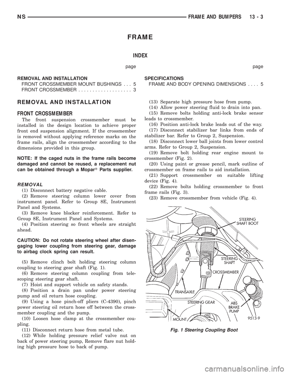
(5) Remove clinch bolt holding steering column
coupling to steering gear shaft (Fig. 1).
(6) Remove steering column coupling from tele-
scoping steering gear shaft.
(7) Hoist and support vehicle on safety stands.
(8) Position a drain pan under power steering
pump and oil return hose coupling.
(9) Using a hose pinch-off pliers (C-4390), pinch
power steering oil return hose off between the cross-
member coupling and the pump.
(10) Loosen hose clamp at the crossmember cou-
pling.
(11) Disconnect return hose from metal tube.
(12) While holding pressure relief valve nut on
back of power steering pump, Remove flare nut hold-
ing high pressure hose to back of pump.(13) Separate high pressure hose from pump.
(14) Allow power steering fluid to drain into pan.
(15) Remove bolts holding anti-lock brake sensor
leads to crossmember.
(16) Position anti-lock brake leads out of the way.
(17) Disconnect stabilizer bar links from ends of
stabilizer bar. Refer to Group 2, Suspension.
(18) Disconnect lower ball joints from lower control
arms. Refer to Group 2, Suspension.
(19) Remove bolt holding rear engine mount to
crossmember (Fig. 2).
(20) Using paint or grease pencil, mark outline of
crossmember on frame rails to aid installation.
(21) Support crossmember on suitable lifting
device (Fig. 4).
(22) Remove bolts holding crossmember to front
frame rails (Fig. 3).
(23) Remove crossmember from vehicle (Fig. 4).
Fig. 1 Steering Coupling Boot
NSFRAME AND BUMPERS 13 - 3