1996 CHRYSLER VOYAGER brake sensor
[x] Cancel search: brake sensorPage 1285 of 1938
(7) Connect lower ball joints to lower control arms.
Refer to Group 2, Suspension.
(8) Connect stabilizer bar links to ends of stabi-
lizer bar. Refer to Group 2, Suspension.
(9) Install bolts to hold anti-lock brake sensor
leads to crossmember.
(10) Install high pressure hose to pump.
(11) Connect return hose to metal tube.
(12) Tighten hose clamp at the crossmember cou-
pling.
(13) Remove pinch-off pliers.
(14) Position steering so front wheels are straight
ahead.
(15) Install steering column coupling to telescoping
steering gear shaft.
(16) Install clinch bolt to hold steering column cou-
pling to steering gear shaft.
(17) Install knee blocker reinforcement. Refer to
Group 8E, Instrument Panel and Systems.
(18) Install steering column lower cover from
instrument panel. Refer to Group 8E, Instrument
Panel and Systems.
(19) Connect battery negative cable.
FRONT CROSSMEMBER MOUNT BUSHINGS
REMOVAL
(1) Using paint or grease pencil, mark outline of
crossmember on frame rails.
(2) Loosen bolts holding crossmember to frame
rails.
(3) Remove bolt on bushing that requires replace-
ment.
(4) Allow crossmember to drop down enough to
gain clearance for bushing removal.
(5) Remove bushing from vehicle.
INSTALLATION
(1) Apply rubber lube or soap to replacement bush-
ing.(2) Insert lower half of bushing into square hole in
crossmember.
(3) Place upper half of bushing on top of cross-
member aligned to receive square tube protruding
upward from lower bushing half.
(4) Squeeze bushing halves together to ensure they
are properly mated.
(5) Lift crossmember upward to close gap between
the bushing and frame.
(6) Verify that lower bushing is fully seated into
crossmember and upper bushing.
(7) Install bolt to hold bushing and crossmember
to frame rail hand tight.
(8) Align crossmember to reference marks on
frame rails.
(9) Tighten crossmember to frame rails attaching
bolts to 163 N´m (120 ft. lbs.) torque.
SPECIFICATIONS
FRAME AND BODY OPENING DIMENSIONS
Frame dimensions are listed in metric scale. All
dimensions are from center to center of Principal
Locating Point (PLP), or from center to center of PLP
and fastener location.
VEHICLE PREPARATION
Position the vehicle on a frame alignment rack,
refer to instructions provided with equipment being
used. Adjust the vehicle PLP heights to the specified
dimension above the work surface (datum line). Ver-
tical dimensions can be taken from the datum line to
the locations indicated were applicable. Refer to (Fig.
5), (Fig. 6), (Fig. 7), (Fig. 8), (Fig. 9), (Fig. 10) and
(Fig. 11) for proper dimensions.
NSFRAME AND BUMPERS 13 - 5
REMOVAL AND INSTALLATION (Continued)
Page 1315 of 1938
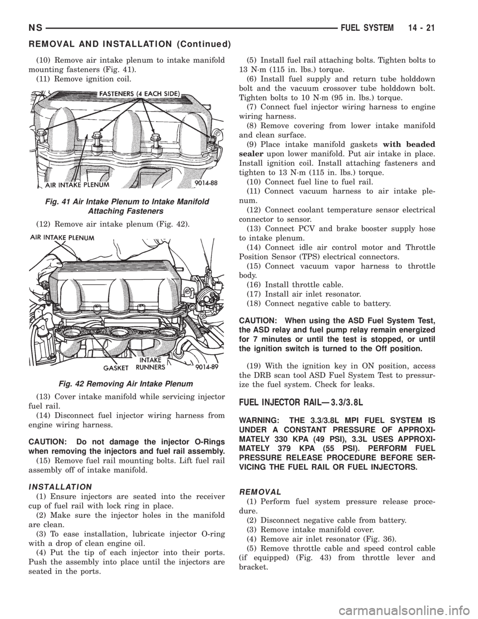
(10) Remove air intake plenum to intake manifold
mounting fasteners (Fig. 41).
(11) Remove ignition coil.
(12) Remove air intake plenum (Fig. 42).
(13) Cover intake manifold while servicing injector
fuel rail.
(14) Disconnect fuel injector wiring harness from
engine wiring harness.
CAUTION: Do not damage the injector O-Rings
when removing the injectors and fuel rail assembly.
(15) Remove fuel rail mounting bolts. Lift fuel rail
assembly off of intake manifold.
INSTALLATION
(1) Ensure injectors are seated into the receiver
cup of fuel rail with lock ring in place.
(2) Make sure the injector holes in the manifold
are clean.
(3) To ease installation, lubricate injector O-ring
with a drop of clean engine oil.
(4) Put the tip of each injector into their ports.
Push the assembly into place until the injectors are
seated in the ports.(5) Install fuel rail attaching bolts. Tighten bolts to
13 N´m (115 in. lbs.) torque.
(6) Install fuel supply and return tube holddown
bolt and the vacuum crossover tube holddown bolt.
Tighten bolts to 10 N´m (95 in. lbs.) torque.
(7) Connect fuel injector wiring harness to engine
wiring harness.
(8) Remove covering from lower intake manifold
and clean surface.
(9) Place intake manifold gasketswith beaded
sealerupon lower manifold. Put air intake in place.
Install ignition coil. Install attaching fasteners and
tighten to 13 N´m (115 in. lbs.) torque.
(10) Connect fuel line to fuel rail.
(11) Connect vacuum harness to air intake ple-
num.
(12) Connect coolant temperature sensor electrical
connector to sensor.
(13) Connect PCV and brake booster supply hose
to intake plenum.
(14) Connect idle air control motor and Throttle
Position Sensor (TPS) electrical connectors.
(15) Connect vacuum vapor harness to throttle
body.
(16) Install throttle cable.
(17) Install air inlet resonator.
(18) Connect negative cable to battery.
CAUTION: When using the ASD Fuel System Test,
the ASD relay and fuel pump relay remain energized
for 7 minutes or until the test is stopped, or until
the ignition switch is turned to the Off position.
(19) With the ignition key in ON position, access
the DRB scan tool ASD Fuel System Test to pressur-
ize the fuel system. Check for leaks.
FUEL INJECTOR RAILÐ3.3/3.8L
WARNING: THE 3.3/3.8L MPI FUEL SYSTEM IS
UNDER A CONSTANT PRESSURE OF APPROXI-
MATELY 330 KPA (49 PSI), 3.3L USES APPROXI-
MATELY 379 KPA (55 PSI). PERFORM FUEL
PRESSURE RELEASE PROCEDURE BEFORE SER-
VICING THE FUEL RAIL OR FUEL INJECTORS.
REMOVAL
(1) Perform fuel system pressure release proce-
dure.
(2) Disconnect negative cable from battery.
(3) Remove intake manifold cover.
(4) Remove air inlet resonator (Fig. 36).
(5) Remove throttle cable and speed control cable
(if equipped) (Fig. 43) from throttle lever and
bracket.
Fig. 41 Air Intake Plenum to Intake Manifold
Attaching Fasteners
Fig. 42 Removing Air Intake Plenum
NSFUEL SYSTEM 14 - 21
REMOVAL AND INSTALLATION (Continued)
Page 1323 of 1938
FUEL INJECTION SYSTEM
INDEX
page page
GENERAL INFORMATION
INTRODUCTION......................... 30
MODES OF OPERATION.................. 30
DESCRIPTION AND OPERATION
AIR CONDITIONING (A/C) CLUTCH RELAYÐ
PCM OUTPUT......................... 41
AIR CONDITIONING PRESSURE
TRANSDUCERÐPCM INPUT............. 33
AIR CONDITIONING SWITCH SENSEÐ
PCM INPUT........................... 33
AUTOMATIC SHUTDOWN (ASD) SENSEÐ
PCM INPUT........................... 33
AUTOMATIC SHUTDOWN RELAYÐPCM
OUTPUT............................. 42
AUTOMATIC TRANSAXLE CONTROL
MODULEÐPCM OUTPUT................ 44
BATTERY VOLTAGEÐPCM INPUT........... 33
BRAKE SWITCHÐPCM INPUT.............. 33
CAMSHAFT POSITION SENSORÐPCM INPUT . 33
CCDBUS .............................. 32
CRANKSHAFT POSITION SENSORÐPCM
INPUT............................... 35
DATA LINK CONNECTORÐPCM OUTPUT..... 44
DUTY CYCLE EVAP CANISTER PURGE
SOLENOIDÐPCM OUTPUT.............. 43
ELECTRONIC EGR TRANSDUCER
SOLENOIDÐPCM OUTPUT.............. 43
ENGINE COOLANT TEMPERATURE SENSORÐ
PCM INPUT........................... 36
FUEL INJECTORSÐPCM OUTPUT.......... 44
FUEL PUMP RELAYÐPCM OUTPUT......... 42
GENERATOR FIELDÐPCM OUTPUT......... 42
HEATED OXYGEN SENSOR (O2S SENSOR)Ð
PCM INPUT........................... 37
IDLE AIR CONTROL MOTORÐPCM OUTPUT . . 42
IGNITION COILÐPCM OUTPUT............. 45
INTAKE AIR TEMPERATURE SENSORÐPCM
INPUT (2.4L ONLY)..................... 41
KNOCK SENSORÐPCM INPUT............. 38
MALFUNCTION INDICATOR (CHECK ENGINE)
LAMPÐPCM OUTPUT.................. 46
MANIFOLD ABSOLUTE PRESSURE (MAP)
SENSORÐPCM INPUT.................. 39
POWERTRAIN CONTROL MODULE (PCM).... 32
PROPORTIONAL PURGE SOLENOID......... 43
SOLID STATE FAN RELAYÐPCM OUTPUT.... 46
SPEED CONTROL SOLENOIDSÐ
PCM OUTPUT......................... 46
SPEED CONTROLÐPCM INPUT............ 39STARTER RELAYÐPCM OUTPUT........... 42
SYSTEM DIAGNOSIS..................... 32
TACHOMETERÐPCM OUTPUT............. 47
THROTTLE BODY....................... 47
THROTTLE POSITION SENSOR (TPS)Ð
PCM INPUT........................... 40
TORQUE CONVERTER CLUTCH SOLENOIDÐ
PCM OUTPUT......................... 46
TRANSAXLE PARK/NEUTRAL SWITCHÐ
PCM INPUT........................... 40
VEHICLE SPEED AND DISTANCEÐ
PCM INPUT........................... 41
DIAGNOSIS AND TESTING
ASD AND FUEL PUMP RELAYS............. 59
CAMSHAFT AND CRANKSHAFT POSITION
SENSOR............................. 61
ENGINE COOLANT TEMPERATURE SENSOR . . 61
HEATED OXYGEN SENSOR............... 61
KNOCK SENSOR........................ 61
MANIFOLD ABSOLUTE PRESSURE (MAP)
SENSOR............................. 60
THROTTLE BODY MINIMUM AIR FLOW
CHECK PROCEDURE................... 62
THROTTLE POSITION SENSOR............ 62
VISUAL INSPECTIONÐ2.4L ENGINE......... 47
VISUAL INSPECTIONÐ3.0L ENGINE......... 52
VISUAL INSPECTIONÐ3.3/3.8L ENGINES..... 55
REMOVAL AND INSTALLATION
AIR CLEANER ELEMENT.................. 70
AUTOMATIC SHUTDOWN (ASD) RELAY...... 64
CAMSHAFT POSITION SENSOR............ 68
CRANKSHAFT POSITION SENSOR.......... 68
DOWNSTREAM OXYGEN SENSOR.......... 69
ENGINE COOLANT TEMPERATURE
SENSORÐ2.4L........................ 70
ENGINE COOLANT TEMPERATURE
SENSORÐ3.0L........................ 71
ENGINE COOLANT TEMPERATURE
SENSORÐ3.3/3.8L..................... 71
FUEL PUMP RELAY...................... 64
IDLE AIR CONTROL MOTOR............... 65
INTAKE AIR TEMPERATURE SENSORÐ2.4L . . . 72
KNOCK SENSOR........................ 70
MANIFOLD ABSOLUTE PRESSURE (MAP)
SENSORÐ2.4/3.3/3.8L.................. 66
MANIFOLD ABSOLUTE PRESSURE (MAP)
SENSORÐ3.0L........................ 66
POWERTRAIN CONTROL MODULE.......... 67
PROPORTIONAL PURGE SOLENOID VALVE . . . 66
NSFUEL SYSTEM 14 - 29
Page 1326 of 1938
IGNITION SWITCH OFF MODE
When the ignition switch is turned to the OFF
position, the following occurs:
²All outputs are turned off.
²No inputs are monitored.
²The PCM shuts down.
DESCRIPTION AND OPERATION
SYSTEM DIAGNOSIS
The PCM can test many of its own input and out-
put circuits. If the PCM senses a fault in a major
system, the PCM stores a Diagnostic Trouble Code
(DTC) in memory.
For DTC information, refer to Group 25, Emission
Control Systems. See On-Board Diagnostics.
CCD BUS
Various controllers and modules exchange informa-
tion through a communications port called the CCD
Bus. The PCM transmits the malfunction indicator
(check engine) lamp On/Off signal, engine RPM and
vehicle load information on the CCD Bus.
POWERTRAIN CONTROL MODULE (PCM)
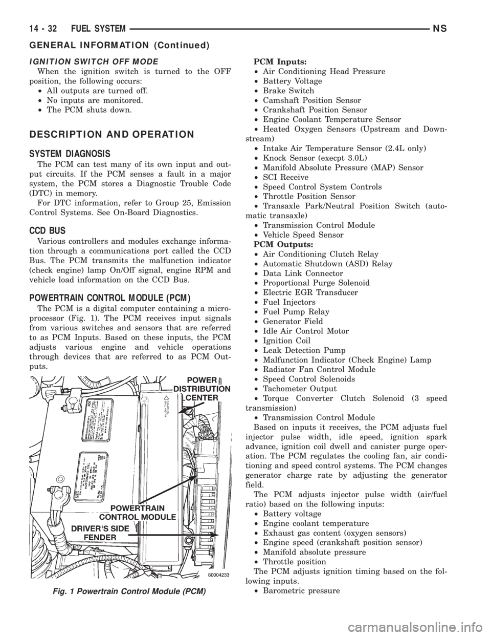
The PCM is a digital computer containing a micro-
processor (Fig. 1). The PCM receives input signals
from various switches and sensors that are referred
to as PCM Inputs. Based on these inputs, the PCM
adjusts various engine and vehicle operations
through devices that are referred to as PCM Out-
puts.PCM Inputs:
²Air Conditioning Head Pressure
²Battery Voltage
²Brake Switch
²Camshaft Position Sensor
²Crankshaft Position Sensor
²Engine Coolant Temperature Sensor
²Heated Oxygen Sensors (Upstream and Down-
stream)
²Intake Air Temperature Sensor (2.4L only)
²Knock Sensor (execpt 3.0L)
²Manifold Absolute Pressure (MAP) Sensor
²SCI Receive
²Speed Control System Controls
²Throttle Position Sensor
²Transaxle Park/Neutral Position Switch (auto-
matic transaxle)
²Transmission Control Module
²Vehicle Speed Sensor
PCM Outputs:
²Air Conditioning Clutch Relay
²Automatic Shutdown (ASD) Relay
²Data Link Connector
²Proportional Purge Solenoid
²Electric EGR Transducer
²Fuel Injectors
²Fuel Pump Relay
²Generator Field
²Idle Air Control Motor
²Ignition Coil
²Leak Detection Pump
²Malfunction Indicator (Check Engine) Lamp
²Radiator Fan Control Module
²Speed Control Solenoids
²Tachometer Output
²Torque Converter Clutch Solenoid (3 speed
transmission)
²Transmission Control Module
Based on inputs it receives, the PCM adjusts fuel
injector pulse width, idle speed, ignition spark
advance, ignition coil dwell and canister purge oper-
ation. The PCM regulates the cooling fan, air condi-
tioning and speed control systems. The PCM changes
generator charge rate by adjusting the generator
field.
The PCM adjusts injector pulse width (air/fuel
ratio) based on the following inputs:
²Battery voltage
²Engine coolant temperature
²Exhaust gas content (oxygen sensors)
²Engine speed (crankshaft position sensor)
²Manifold absolute pressure
²Throttle position
The PCM adjusts ignition timing based on the fol-
lowing inputs.
²Barometric pressure
Fig. 1 Powertrain Control Module (PCM)
14 - 32 FUEL SYSTEMNS
GENERAL INFORMATION (Continued)
Page 1327 of 1938
²Engine coolant temperature
²Engine speed (crankshaft position sensor)
²Intake air temperature (2.4L only)
²Manifold absolute pressure
²Throttle position
²Transaxle gear selection (park/neutral switch)
The PCM also adjusts engine idle speed through
the idle air control motor based on the following
inputs.
²Air conditioning select switch head pressure
²Brake switch
²Engine coolant temperature
²Engine speed (crankshaft position sensor)
²Manifold absolute pressure
²Throttle position
²Transaxle gear selection (park/neutral switch)
²Vehicle distance (speed)
The Automatic Shutdown (ASD) and fuel pump
relays are located in the Power Distribution Center
(PDC).
The camshaft position sensor (distributor pick-up
signal 3.0L) and crankshaft position sensor signals
are sent to the PCM. If the PCM does not receive
both signals within approximately one second of
engine cranking, it deactivates the ASD relay and
fuel pump relay. When these relays are deactivated,
power is shut off to the fuel injectors, ignition coil,
oxygen sensor heating element and fuel pump.
The PCM contains a voltage converter that
changes battery voltage to a regulated 8.0 volts to
power the camshaft position sensor, crankshaft posi-
tion sensor and vehicle speed sensor. The PCM also
provides a 5.0 volt supply for the manifold absolute
pressure sensor, throttle position sensor and engine
coolant temperature sensor.
AIR CONDITIONING PRESSURE TRANSDUCERÐ
PCM INPUT
The Powertrain Control Module (PCM) monitors
the A/C compressor discharge (high side) pressure
through the air conditioning pressure transducer.
The transducer supplies an input to the PCM. The
PCM engages the A/C compressor clutch if pressure
is sufficient for A/C system operation.
AIR CONDITIONING SWITCH SENSEÐPCM INPUT
When the air conditioning or defrost switch is put
in the ON position and the low pressure switch, com-
bination valve, and high pressure switch close, the
PCM receives an A/C input. After receiving this
input, the PCM activates the A/C compressor clutch
by grounding the A/C clutch relay. The PCM also
adjusts idle speed to a scheduled RPM to compensate
for increased engine load.
AUTOMATIC SHUTDOWN (ASD) SENSEÐPCM
INPUT
The ASD sense circuit informs the PCM when the
ASD relay energizes. A 12 volt signal at this input
indicates to the PCM that the ASD has been acti-
vated. This input is used only to sense that the ASD
relay is energized.
When energized, the ASD relay supplies battery
voltage to the fuel injectors, ignition coils and the
heating element in each oxygen sensor. If the PCM
does not receive 12 volts from this input after
grounding the ASD relay, it sets a Diagnostic Trouble
Code (DTC).
BATTERY VOLTAGEÐPCM INPUT
The PCM monitors the battery voltage input to
determine fuel injector pulse width and generator
field control.
If battery voltage is low the PCM will increase
injector pulse width (period of time that the injector
is energized).
BRAKE SWITCHÐPCM INPUT
When the brake switch is activated, the PCM
receives an input indicating that the brakes are
being applied. After receiving this input the PCM
maintains idle speed to a scheduled RPM through
control of the idle air control motor. The brake switch
is mounted on the brake pedal support bracket.
CAMSHAFT POSITION SENSORÐPCM INPUT
The PCM determines fuel injection synchronization
and cylinder identification from inputs provided by
the camshaft position sensor and crankshaft position
sensor. From the two inputs, the PCM determines
crankshaft position.
3.3/3.8L
The sensor generates pulses as groups of notches
on the camshaft sprocket pass underneath it (Fig. 2).
The PCM keeps track of crankshaft rotation and
identifies each cylinder by the pulses generated by
the notches on the camshaft sprocket. Four crank-
shaft pulses follow each group of camshaft pulses.
When the PCM receives two camshaft pulses fol-
lowed by the long flat spot on the camshaft sprocket,
it knows that the crankshaft timing marks for cylin-
der one are next (on driveplate). When the PCM
receives one camshaft pulse after the long flat spot
on the sprocket, cylinder number two crankshaft tim-
ing marks are next. After 3 camshaft pulses, the
PCM knows cylinder four crankshaft timing marks
follow. One camshaft pulse after the three pulses
indicates cylinder five. The two camshaft pulses after
cylinder 5 signals cylinder six (Fig. 3). The PCM can
synchronize on cylinders 1 or 4.
NSFUEL SYSTEM 14 - 33
DESCRIPTION AND OPERATION (Continued)
Page 1334 of 1938
a fixed vehicle speed has been selected. The speed
control RESUME voltage indicates the previous fixed
speed is requested. The speed control CANCEL volt-
age tells the PCM to deactivate but retain set speed
in memory (same as depressing the brake pedal). The
speed control OFF voltage tells the PCM that the
speed control system has deactivated. Refer to Group
8H for more speed control information.
TRANSAXLE PARK/NEUTRAL SWITCHÐPCM
INPUT
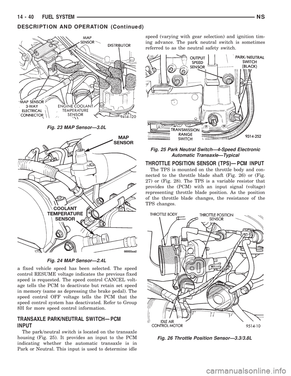
The park/neutral switch is located on the transaxle
housing (Fig. 25). It provides an input to the PCM
indicating whether the automatic transaxle is in
Park or Neutral. This input is used to determine idlespeed (varying with gear selection) and ignition tim-
ing advance. The park neutral switch is sometimes
referred to as the neutral safety switch.
THROTTLE POSITION SENSOR (TPS)ÐPCM INPUT
The TPS is mounted on the throttle body and con-
nected to the throttle blade shaft (Fig. 26) or (Fig.
27) or (Fig. 28). The TPS is a variable resistor that
provides the (PCM) with an input signal (voltage)
representing throttle blade position. As the position
of the throttle blade changes, the resistance of the
TPS changes.
Fig. 23 MAP SensorÐ3.0L
Fig. 24 MAP SensorÐ2.4L
Fig. 25 Park Neutral SwitchÐ4-Speed Electronic
Automatic TransaxleÐTypical
Fig. 26 Throttle Position SensorÐ3.3/3.8L
14 - 40 FUEL SYSTEMNS
DESCRIPTION AND OPERATION (Continued)
Page 1345 of 1938
(22) Check the accessory drive belt tension.
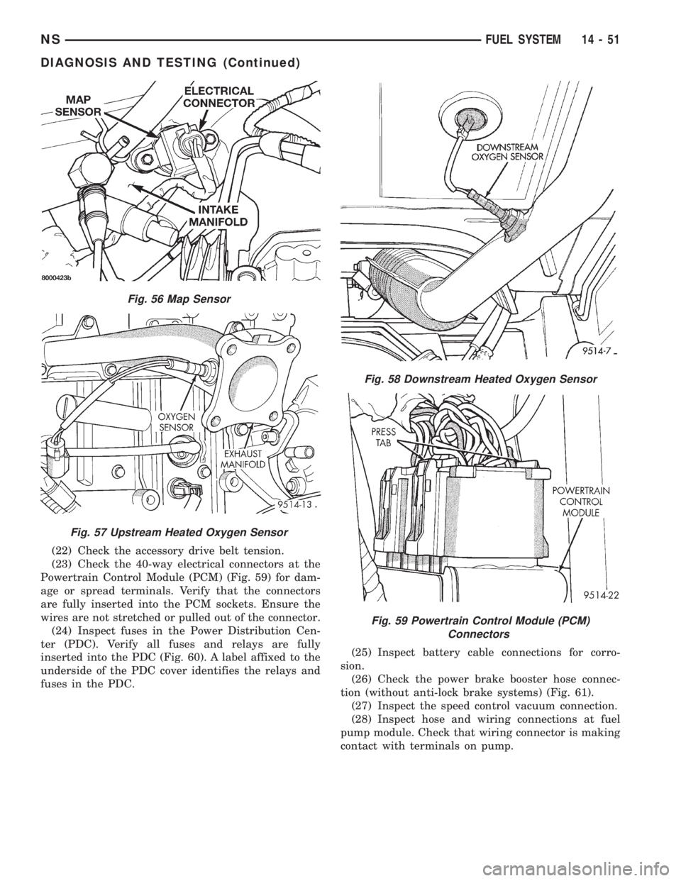
(23) Check the 40-way electrical connectors at the
Powertrain Control Module (PCM) (Fig. 59) for dam-
age or spread terminals. Verify that the connectors
are fully inserted into the PCM sockets. Ensure the
wires are not stretched or pulled out of the connector.
(24) Inspect fuses in the Power Distribution Cen-
ter (PDC). Verify all fuses and relays are fully
inserted into the PDC (Fig. 60). A label affixed to the
underside of the PDC cover identifies the relays and
fuses in the PDC.(25) Inspect battery cable connections for corro-
sion.
(26) Check the power brake booster hose connec-
tion (without anti-lock brake systems) (Fig. 61).
(27) Inspect the speed control vacuum connection.
(28) Inspect hose and wiring connections at fuel
pump module. Check that wiring connector is making
contact with terminals on pump.
Fig. 56 Map Sensor
Fig. 57 Upstream Heated Oxygen Sensor
Fig. 58 Downstream Heated Oxygen Sensor
Fig. 59 Powertrain Control Module (PCM)
Connectors
NSFUEL SYSTEM 14 - 51
DIAGNOSIS AND TESTING (Continued)
Page 1379 of 1938
the intake manifold. Refer to Group 11, Exhaust Sys-
tem and Intake Manifold for information.
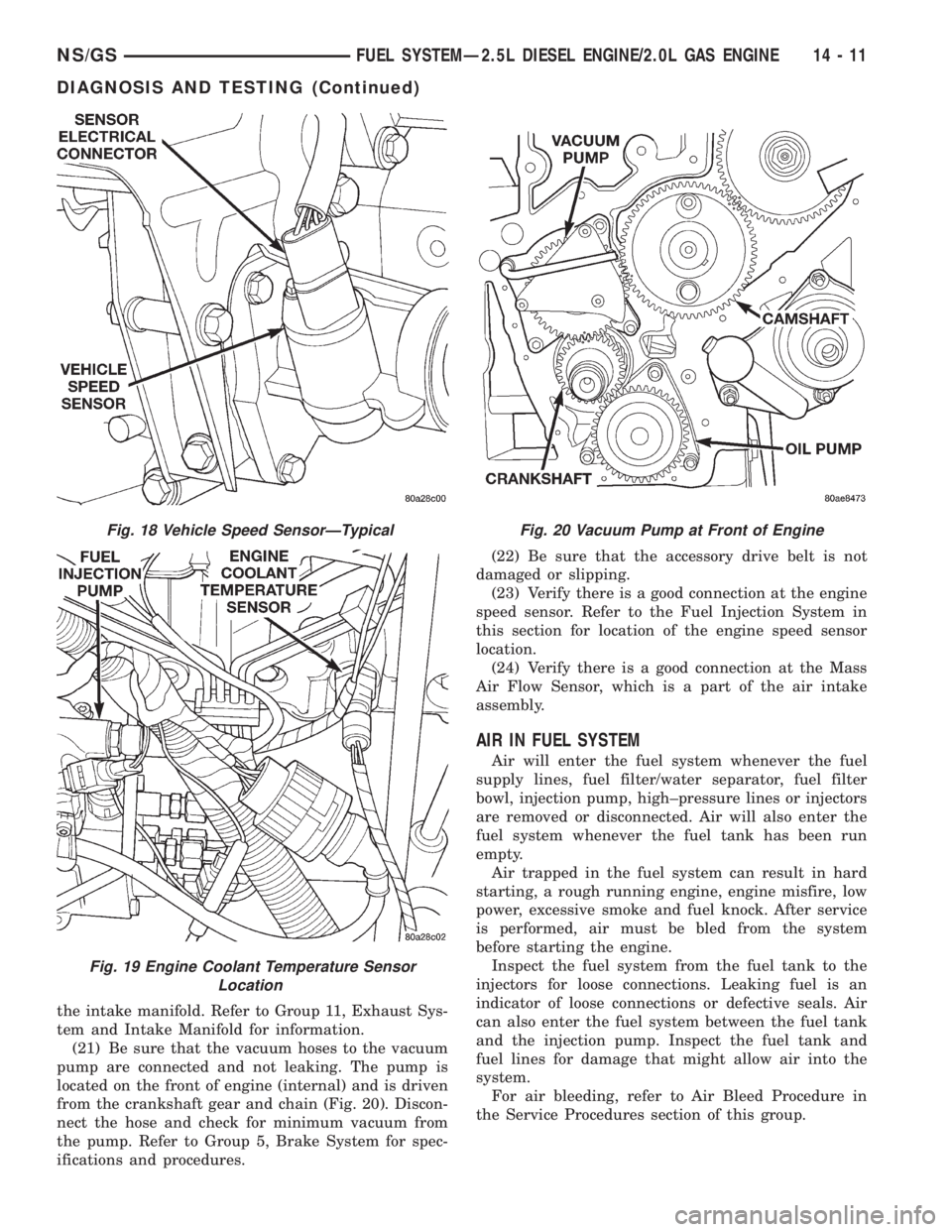
(21) Be sure that the vacuum hoses to the vacuum
pump are connected and not leaking. The pump is
located on the front of engine (internal) and is driven
from the crankshaft gear and chain (Fig. 20). Discon-
nect the hose and check for minimum vacuum from
the pump. Refer to Group 5, Brake System for spec-
ifications and procedures.(22) Be sure that the accessory drive belt is not
damaged or slipping.
(23) Verify there is a good connection at the engine
speed sensor. Refer to the Fuel Injection System in
this section for location of the engine speed sensor
location.
(24) Verify there is a good connection at the Mass
Air Flow Sensor, which is a part of the air intake
assembly.
AIR IN FUEL SYSTEM
Air will enter the fuel system whenever the fuel
supply lines, fuel filter/water separator, fuel filter
bowl, injection pump, high±pressure lines or injectors
are removed or disconnected. Air will also enter the
fuel system whenever the fuel tank has been run
empty.
Air trapped in the fuel system can result in hard
starting, a rough running engine, engine misfire, low
power, excessive smoke and fuel knock. After service
is performed, air must be bled from the system
before starting the engine.
Inspect the fuel system from the fuel tank to the
injectors for loose connections. Leaking fuel is an
indicator of loose connections or defective seals. Air
can also enter the fuel system between the fuel tank
and the injection pump. Inspect the fuel tank and
fuel lines for damage that might allow air into the
system.
For air bleeding, refer to Air Bleed Procedure in
the Service Procedures section of this group.
Fig. 18 Vehicle Speed SensorÐTypical
Fig. 19 Engine Coolant Temperature Sensor
Location
Fig. 20 Vacuum Pump at Front of Engine
NS/GSFUEL SYSTEMÐ2.5L DIESEL ENGINE/2.0L GAS ENGINE 14 - 11
DIAGNOSIS AND TESTING (Continued)