1996 CHRYSLER VOYAGER driver seat adjustment
[x] Cancel search: driver seat adjustmentPage 96 of 1938

ADJUSTER REAR DRUM BRAKE (AUTOMATIC)
The rear drum brakes on this vehicle automatically
adjust, when required, during the normal operation
of the vehicle every time the brakes are applied. Use
the following procedure to test the operation of the
automatic adjuster.
Place the vehicle on a hoist with a helper in the
driver's seat to apply the brakes. Remove the access
plug from the adjustment hole in each brake support
plate to provide visual access of the brake adjuster
star wheel.
Remove the park brake cable, for the wheel of the
vehicle that is being worked on, from the park brake
cable equalizer (Fig. 12). This is required to gain
access to the star wheel. If the cable is not removed
from the equalizer, the cable and spring inside of the
brake drum is in the way of the star wheel.
To eliminate the condition where maximum adjust-
ment of the rear brake shoes, does not allow the
automatic adjuster to operate when tested, back the
star wheel off approximately 30 notches. It will be
necessary to hold the adjuster lever away from the
star wheel to permit this adjustment.
Have the helper apply the brakes. Upon applica-
tion of the brake pedal, the adjuster lever lever
should move down, turning the adjuster star wheel.
Thus, a definite rotation of the adjuster star wheel
can be observed if the automatic adjuster is working
properly. If one or more adjusters do not function
properly, the respective drum must be removed for
adjuster servicing.
BRAKE ROTOR
Any servicing of the rotor requires extreme care to
maintain the rotor to within service tolerances to
ensure proper brake action.Before refinishing or refacing a rotor, the rotor
should be checked and inspected for the following
conditions:
Braking surface scoring, rust, impregnation of lin-
ing material and worn ridges.
Excessive rotor lateral runout or wobble.
Thickness variation in braking surface of the rotor
(Parallelism).
Dishing or distortion in braking surface of the
rotor (Flatness).
If a vehicle has not been driven for a period of
time, the rotors will rust in the area not covered by
the brake lining and cause noise and chatter when
the brakes are applied.
Excessive wear and scoring of the rotor can cause
temporary improper lining contact if ridges are not
removed from braking surface of rotor before instal-
lation of new brake shoe assemblies.
Some discoloration and/or wear of the rotor surface
is normal and does not require resurfacing when lin-
ings are replaced.
Excessive runout or wobble in a rotor can increase
pedal travel due to piston knock-back. This will also
increase guide pin bushing wear due to the tendency
of the caliper to follow rotor wobble.
Thickness variation in a rotor can also result in
pedal pulsation, chatter and surge due to variation in
brake output. This can also be caused by excessive
runout in the rotor and/or the hub.
Dishing or distortion can be caused by extreme
heat and abuse of the brakes.
CHECKING ROTOR FOR RUNOUT AND
THICKNESS
NOTE: The procedure for checking rotor runout
and thickness is the same for the front and rear
rotor. If there is a specification difference between
the front and rear rotor it will be designated as
such in the specifications of the following proce-
dure.
On-vehicle rotor runout is the combination of the
individual runout of the hub face and the runout of
the rotor. (The hub and rotor runouts are separable).
To measure runout on the vehicle, remove the wheel
and reinstall the lug nuts tightening the rotor to the
hub. Mount Dial Indicator, Special Tool C-3339 with
Mounting Adaptor, Special Tool SP- 1910 on steering
arm. Dial indicator plunger should contact braking
surface of rotor approximately 10 mm (0.393 in.)
from outer edge of rotor (Fig. 13). Check lateral
runout on both sides of rotor. Lateral runout of the
rotor should not exceed 0.13 mm (0.005 inch).
If lateral runout is in excess of the specification,
check the lateral runout of the hub face. Before
removing rotor from hub, make a chalk mark across
Fig. 12 Park Brake Cable Equlizer
5 - 14 BRAKESNS
DIAGNOSIS AND TESTING (Continued)
Page 115 of 1938

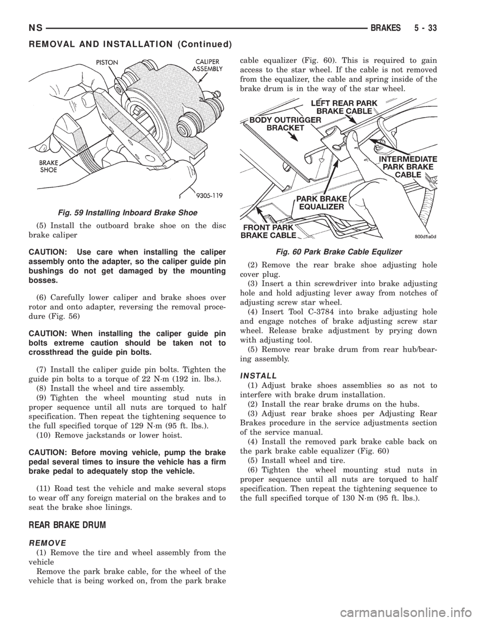
(5) Install the outboard brake shoe on the disc
brake caliper
CAUTION: Use care when installing the caliper
assembly onto the adapter, so the caliper guide pin
bushings do not get damaged by the mounting
bosses.
(6) Carefully lower caliper and brake shoes over
rotor and onto adapter, reversing the removal proce-
dure (Fig. 56)
CAUTION: When installing the caliper guide pin
bolts extreme caution should be taken not to
crossthread the guide pin bolts.
(7) Install the caliper guide pin bolts. Tighten the
guide pin bolts to a torque of 22 N´m (192 in. lbs.).
(8) Install the wheel and tire assembly.
(9) Tighten the wheel mounting stud nuts in
proper sequence until all nuts are torqued to half
specification. Then repeat the tightening sequence to
the full specified torque of 129 N´m (95 ft. lbs.).
(10) Remove jackstands or lower hoist.
CAUTION: Before moving vehicle, pump the brake
pedal several times to insure the vehicle has a firm
brake pedal to adequately stop the vehicle.
(11) Road test the vehicle and make several stops
to wear off any foreign material on the brakes and to
seat the brake shoe linings.
REAR BRAKE DRUM
REMOVE
(1) Remove the tire and wheel assembly from the
vehicle
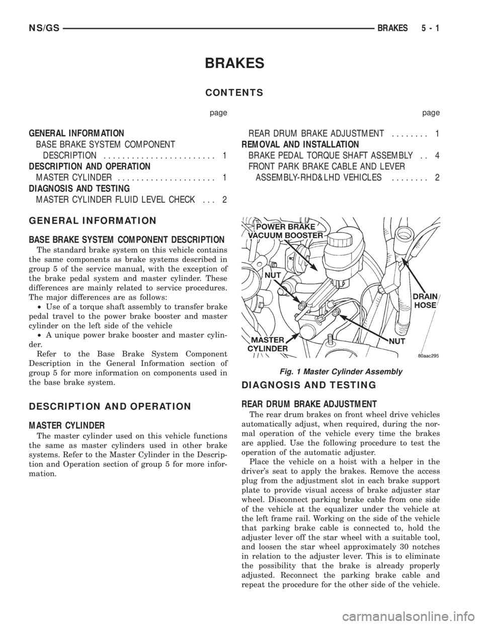
Remove the park brake cable, for the wheel of the
vehicle that is being worked on, from the park brakecable equalizer (Fig. 60). This is required to gain
access to the star wheel. If the cable is not removed
from the equalizer, the cable and spring inside of the
brake drum is in the way of the star wheel.
(2) Remove the rear brake shoe adjusting hole
cover plug.
(3) Insert a thin screwdriver into brake adjusting
hole and hold adjusting lever away from notches of
adjusting screw star wheel.
(4) Insert Tool C-3784 into brake adjusting hole
and engage notches of brake adjusting screw star
wheel. Release brake adjustment by prying down
with adjusting tool.
(5) Remove rear brake drum from rear hub/bear-
ing assembly.
INSTALL
(1) Adjust brake shoes assemblies so as not to
interfere with brake drum installation.
(2) Install the rear brake drums on the hubs.
(3) Adjust rear brake shoes per Adjusting Rear
Brakes procedure in the service adjustments section
of the service manual.
(4) Install the removed park brake cable back on
the park brake cable equalizer (Fig. 60)
(5) Install wheel and tire.
(6) Tighten the wheel mounting stud nuts in
proper sequence until all nuts are torqued to half
specification. Then repeat the tightening sequence to
the full specified torque of 130 N´m (95 ft. lbs.).
Fig. 59 Installing Inboard Brake Shoe
Fig. 60 Park Brake Cable Equlizer
NSBRAKES 5 - 33
REMOVAL AND INSTALLATION (Continued)
Page 193 of 1938

(7) Install wheel lug nuts on 3 of the wheel mount-
ing studs to protect the stud threads from damage by
the vise jaws. Mount the hub/bearing assembly in a
vise (Fig. 50). Using Puller, Special Tool C-4693
installed as shown in (Fig. 50) remove the tone wheel
from the hub/bearing assembly.
INSTALL
(1) Place hub/bearing assembly in an arbor press
supported by Receiver, Special Tool, 6062A±3 (Fig.
51). Position Driver, Special Tool 6908±1 with under-
cut side facing up (Fig. 51) on top of the tone wheel.
(2) Press the tone wheel onto the hub/bearing
assembly until it is flush with the end of hub shaft
(Fig. 52).
(3) Install the 4 hub/bearing to axle flange mount-
ing bolts into the 4 mounting holes in the flange of
the rear axle.(4) Install the rear brake support plate on the 4
mounting bolts installed in the flange of the rear
axle.
(5) Align the rear hub/bearing assembly with the 4
mounting bolts and start mounting bolts into hub/
bearing assembly. Tighten the 4 bolts in a criss-cross
pattern until the hub/bearing and brake support
plate is fully and squarely seated onto flange of rear
axle.
(6) Tighten the 4 hub/bearing mounting bolts (Fig.
48) to a torque of 129 N´m (95 ft. lbs.)
(7) Install the rear wheel speed sensor on the rear
hub/bearing flange (Fig. 47). Install the speed sensor
attaching bolt and tighten to a torque of 12 N´m (105
in. lbs.).
(8) Check the air gap between the face of the
wheel speed sensor and the top surface of the tone-
wheel. Air gap must be less then the maximum
allowable tolerance of 1.2 mm (.047 in.).
(9) Install the brake drum onto the rear hub/bear-
ing assembly.
(10) Install rear wheel and tire assembly, tighten
wheel stud nuts to 129 N´m (95 ft. lbs.).
(11) Adjust the rear brakes, (See Adjusting Service
Brakes) in Service Adjustments section in this group
of the service manual.
TONE WHEEL (REAR AWD)
The rear tone wheel on all wheel drive applications
is an integral part of each rear axle outer C/V joint.
If the rear tone wheel on an all wheel drive vehicle
requires replacement it can not be replace as a sep-
arate component of the rear axle. Tone wheel replace-
ment will require the replacement of the rear axle.
Refer to Differential And Driveline in this service
manual for the rear axle replacement procedure.
Fig. 50 Tone Wheel Removal From Hub/Bearing
Assembly
Fig. 51 Installing Tone Wheel On Hub/Bearing
Assembly
Fig. 52 Correctly Installed Tone Wheel
NSBRAKES 5 - 111
REMOVAL AND INSTALLATION (Continued)
Page 195 of 1938

BRAKES
CONTENTS
page page
GENERAL INFORMATION
BASE BRAKE SYSTEM COMPONENT
DESCRIPTION........................ 1
DESCRIPTION AND OPERATION
MASTER CYLINDER..................... 1
DIAGNOSIS AND TESTING
MASTER CYLINDER FLUID LEVEL CHECK . . . 2REAR DRUM BRAKE ADJUSTMENT........ 1
REMOVAL AND INSTALLATION
BRAKE PEDAL TORQUE SHAFT ASSEMBLY . . 4
FRONT PARK BRAKE CABLE AND LEVER
ASSEMBLY-RHD&LHD VEHICLES........ 2
GENERAL INFORMATION
BASE BRAKE SYSTEM COMPONENT DESCRIPTION
The standard brake system on this vehicle contains
the same components as brake systems described in
group 5 of the service manual, with the exception of
the brake pedal system and master cylinder. These
differences are mainly related to service procedures.
The major differences are as follows:
²Use of a torque shaft assembly to transfer brake
pedal travel to the power brake booster and master
cylinder on the left side of the vehicle
²A unique power brake booster and master cylin-
der.
Refer to the Base Brake System Component
Description in the General Information section of
group 5 for more information on components used in
the base brake system.
DESCRIPTION AND OPERATION
MASTER CYLINDER
The master cylinder used on this vehicle functions
the same as master cylinders used in other brake
systems. Refer to the Master Cylinder in the Descrip-
tion and Operation section of group 5 for more infor-
mation.
DIAGNOSIS AND TESTING
REAR DRUM BRAKE ADJUSTMENT
The rear drum brakes on front wheel drive vehicles
automatically adjust, when required, during the nor-
mal operation of the vehicle every time the brakes
are applied. Use the following procedure to test the
operation of the automatic adjuster.
Place the vehicle on a hoist with a helper in the
driver's seat to apply the brakes. Remove the access
plug from the adjustment slot in each brake support
plate to provide visual access of brake adjuster star
wheel. Disconnect parking brake cable from one side
of the vehicle at the equalizer under the vehicle at
the left frame rail. Working on the side of the vehicle
that parking brake cable is connected to, hold the
adjuster lever off the star wheel with a suitable tool,
and loosen the star wheel approximately 30 notches
in relation to the adjuster lever. This is to eliminate
the possibility that the brake is already properly
adjusted. Reconnect the parking brake cable and
repeat the procedure for the other side of the vehicle.
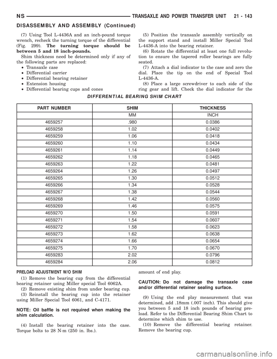
Fig. 1 Master Cylinder Assembly
NS/GSBRAKES 5 - 1
Page 483 of 1938

HEADLAMP ALIGNMENT
INDEX
page page
SERVICE PROCEDURES
HEADLAMP ALIGNMENT PREPARATION...... 5ADJUSTMENTS
HEADLAMP/FOG LAMP ADJUSTMENT USING
ALIGNMENT SCREEN.................. 5
SERVICE PROCEDURES
HEADLAMP ALIGNMENT PREPARATION
(1) Verify headlamp dimmer switch and high beam
indicator operation.
(2) Verify that the headlamp leveling switch is in
the ª0º position.
(3) Inspect and correct damaged or defective com-
ponents that could interfere with proper headlamp
alignment.
(4) Verify proper tire inflation.
(5) Clean headlamp lenses.
(6) Verify that luggage area is loaded as the vehi-
cle is routinely used.
(7) Fuel tank should be FULL. Add 2.94 kg (6.5
lbs.) of weight over the fuel tank for each estimated
gallon of missing fuel.
ADJUSTMENTS
HEADLAMP/FOG LAMP ADJUSTMENT USING
ALIGNMENT SCREEN
ALIGNMENT SCREEN PREPARATION
(1) Position vehicle on a level surface perpendicu-
lar to a flat wall 10 meters (32.8 ft.) away from front
of headlamp lens (Fig. 1).
(2) Place 75 kg in the driver's seat to simulate the
ride height of the vehicle when driven.
(3) If necessary, tape a line on the floor 10 meters
(32.8 ft) away from and parallel to the wall.
(4) From the floor up 1.27 meters (5 ft), tape a line
on the wall at the centerline of the vehicle. Sight
along the centerline of the vehicle (from rear of vehi-
cle forward) to verify accuracy of the line placement.
NS/GSLAMPS 8L - 5
Page 513 of 1938

REMOTE KEYLESS ENTRY
INDEX
page page
DESCRIPTION AND OPERATION
INTRODUCTION......................... 5
VEHICLE ACCESS CODE (VAC)
PROGRAMMING........................ 5
DIAGNOSIS AND TESTING
RKE DIAGNOSTICS....................... 5
SERVICE PROCEDURES
HORN CHIRP DISABLE OR ENABLE.......... 6REMOVAL AND INSTALLATION
RKE MODULE........................... 6
ADJUSTMENTS
PROGRAMMING RKE MODULE.............. 6
SPECIFICATIONS
RKE TRANSMITTER BATTERY.............. 6
RKE TRANSMITTER RANGE................ 6
DESCRIPTION AND OPERATION
INTRODUCTION
The key fob transmitter has three buttons to actu-
ate and program the Remote Keyless Entry (RKE)
system (Fig. 1).
²UNLOCK: Pressing the UNLOCK button once
will unlock the driver door and activate the illumi-
nated entry system and disarm Vehicle Theft Secu-
rity System, if equipped. Pressing the UNLOCK
button twice within five seconds will unlock all doors
and activate the illuminated entry system.
²LOCK: Pressing the LOCK button locks all
doors and sounds horn (chirp) and arm the Vehicle
Theft Security System. The chirp verifies the door
lock operation.
²PANIC: Pressing the PANIC button sounds the
horns at half second intervals, flashes the exterior
lamps, and turns ON the interior lamps. The panic
alarm will remain on for three minutes, or until the
PANIC button is actuated again or the ignition
switch is turned to the RUN position.
²The Remote Keyless Entry Module is capable of
retaining the transmitter Vehicle Access Code(s)
(VAC) in its memory even after vehicle power has
been interrupted.
²The RKE system activates the optional memory
seat and mirror system, if equipped. Two primary
key fob transmitters can be programmed to actuate
memory seat and mirror setting 1 or 2. Two addi-
tional key fob transmitters can be added, but they
will not be able to operate the memory seat and mir-
ror system. Refer to Group 8R, Power Seats and
Group 8T, Power Mirrors for memory system infor-
mation.
VEHICLE ACCESS CODE (VAC) PROGRAMMING
The RKE module is capable of retaining up to four
different Vehicle Access Codes. Whenever the vehicle
battery power is interrupted the RKE Module willretain all vehicle access codes in its memory. When
replacing or adding a key fob transmitter (maximum
4) a functional key fob transmitter is required to pro-
gram the RKE Module to accept the new Vehicle
Access Code. If a functional key fob transmitter is
not available, a scan tool (DRB) can be used to pro-
gram the RKE Module. Refer to the proper Body
Diagnostic Procedures manual for Vehicle Access
Code programming procedures using a scan tool.
DIAGNOSIS AND TESTING
RKE DIAGNOSTICS
Refer to Group 8W, Wiring Diagrams for circuit
information and component locations. Refer to the
proper Body Diagnostic Procedures manual for test-
ing the Remote Keyless Entry system using a scan
tool (DRB). Also refer to other interrelated systems
groups within this manual:
²Group 8Q, Vehicle Theft Security System
²Group 8R, Power Seats
²Group 8T, Power Mirrors
Fig. 1 Key Fob Transmitter
NSPOWER DOOR LOCKS 8P - 5
Page 1617 of 1938

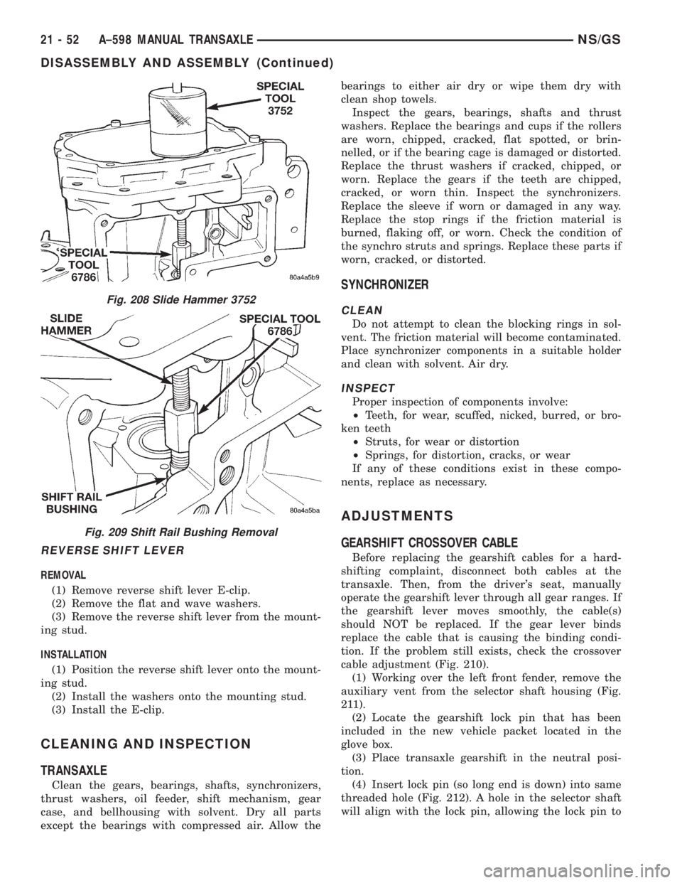
(7) Using Tool L-4436A and an inch-pound torque
wrench, recheck the turning torque of the differential
(Fig. 299).The turning torque should be
between 5 and 18 inch-pounds.
Shim thickness need be determined only if any of
the following parts are replaced:
²Transaxle case
²Differential carrier
²Differential bearing retainer
²Extension housing
²Differential bearing cups and cones
PRELOAD ADJUSTMENT W/O SHIM
(1) Remove the bearing cup from the differential
bearing retainer using Miller special Tool 6062A.
(2) Remove existing shim from under bearing cup.
(3) Reinstall the bearing cup into the retainer
using Miller Special Tool 6061, and C-4171.
NOTE: Oil baffle is not required when making the
shim calculation.
(4) Install the bearing retainer into the case.
Torque bolts to 28 N´m (250 in. lbs.).(5) Position the transaxle assembly vertically on
the support stand and install Miller Special Tool
L-4436-A into the bearing retainer.
(6) Rotate the differential at least one full revolu-
tion to ensure the tapered roller bearings are fully
seated.
(7) Attach a dial indicator to the case and zero the
dial. Place the tip on the end of Special Tool
L-4436-A.
(8) Place a large screwdriver to each side of the
ring gear and lift. Check the dial indicator for the
amount of end play.
CAUTION: Do not damage the transaxle case
and/or differential retainer sealing surface.
(9) Using the end play measurement that was
determined, add .18mm (.007 inch). This should give
you between 5 and 18 inch pounds of bearing pre-
load. Refer to the Differential Bearing Shim Chart to
determine which shim to use.
(10) Remove the differential bearing retainer.
Remove the bearing cup.
DIFFERENTIAL BEARING SHIM CHART
PART NUMBER SHIM THICKNESS
MM INCH
4659257 .980 0.0386
4659258 1.02 0.0402
4659259 1.06 0.0418
4659260 1.10 0.0434
4659261 1.14 0.0449
4659262 1.18 0.0465
4659263 1.22 0.0481
4659264 1.26 0.0497
4659265 1.30 0.0512
4659266 1.34 0.0528
4659267 1.38 0.0544
4659268 1.42 0.0560
4659269 1.46 0.0575
4659270 1.50 0.0591
4659271 1.54 0.0607
4659272 1.58 0.0623
4659273 1.62 0.0638
4659274 1.66 0.0654
4659275 1.70 0.0670
4659283 2.02 0.0796
4659284 2.06 0.0812
NSTRANSAXLE AND POWER TRANSFER UNIT 21 - 143
DISASSEMBLY AND ASSEMBLY (Continued)
Page 1708 of 1938

REVERSE SHIFT LEVER
REMOVAL
(1) Remove reverse shift lever E-clip.
(2) Remove the flat and wave washers.
(3) Remove the reverse shift lever from the mount-
ing stud.
INSTALLATION
(1) Position the reverse shift lever onto the mount-
ing stud.
(2) Install the washers onto the mounting stud.
(3) Install the E-clip.
CLEANING AND INSPECTION
TRANSAXLE
Clean the gears, bearings, shafts, synchronizers,
thrust washers, oil feeder, shift mechanism, gear
case, and bellhousing with solvent. Dry all parts
except the bearings with compressed air. Allow thebearings to either air dry or wipe them dry with
clean shop towels.
Inspect the gears, bearings, shafts and thrust
washers. Replace the bearings and cups if the rollers
are worn, chipped, cracked, flat spotted, or brin-
nelled, or if the bearing cage is damaged or distorted.
Replace the thrust washers if cracked, chipped, or
worn. Replace the gears if the teeth are chipped,
cracked, or worn thin. Inspect the synchronizers.
Replace the sleeve if worn or damaged in any way.
Replace the stop rings if the friction material is
burned, flaking off, or worn. Check the condition of
the synchro struts and springs. Replace these parts if
worn, cracked, or distorted.
SYNCHRONIZER
CLEAN
Do not attempt to clean the blocking rings in sol-
vent. The friction material will become contaminated.
Place synchronizer components in a suitable holder
and clean with solvent. Air dry.
INSPECT
Proper inspection of components involve:
²Teeth, for wear, scuffed, nicked, burred, or bro-
ken teeth
²Struts, for wear or distortion
²Springs, for distortion, cracks, or wear
If any of these conditions exist in these compo-
nents, replace as necessary.
ADJUSTMENTS
GEARSHIFT CROSSOVER CABLE
Before replacing the gearshift cables for a hard-
shifting complaint, disconnect both cables at the
transaxle. Then, from the driver's seat, manually
operate the gearshift lever through all gear ranges. If
the gearshift lever moves smoothly, the cable(s)
should NOT be replaced. If the gear lever binds
replace the cable that is causing the binding condi-
tion. If the problem still exists, check the crossover
cable adjustment (Fig. 210).
(1) Working over the left front fender, remove the
auxiliary vent from the selector shaft housing (Fig.
211).
(2) Locate the gearshift lock pin that has been
included in the new vehicle packet located in the
glove box.
(3) Place transaxle gearshift in the neutral posi-
tion.
(4) Insert lock pin (so long end is down) into same
threaded hole (Fig. 212). A hole in the selector shaft
will align with the lock pin, allowing the lock pin to
Fig. 208 Slide Hammer 3752
Fig. 209 Shift Rail Bushing Removal
21 - 52 A±598 MANUAL TRANSAXLENS/GS
DISASSEMBLY AND ASSEMBLY (Continued)