Page 33 of 44
38-33
Multi-Function Transmission Range (TR)
Switch -F125-, removing and installing
Removing
- Removing left transmission support page 37
-
125
.
- Unbolt Multi-Function Transmission Range (TR)
Switch -F125- from transmission and pull off
from shift rod.
Installing
Note:
Set Multi-Function Transmission Range (TR) Switch -F125- onto shift rod
in centered manner. Do not cant and do not set with force. Risk of
damage at switch terminals. - Connect Multi-Function Transmission Range (TR) Switch -F125- on
shift rod. Flap part at splines in switch -3- must align with flat part of
shift rod -1-.
Pa
ge 33 of 44 Oil
pan, oil strainer and valve bod
y, removin
g and installin
g
11/20/2002 htt
p://127.0.0.1:8080/audi/servlet/Dis
play?action=Goto&t
yp
e=re
pair&id=AUDI.B5.AT01.38.1
Page 34 of 44
38-34
Tightening torques - Rotate switch until the alignment hole -4- at switch housing can be
fitted on the alignment pin -2- at transmission housing.
- Installing left transmission support page 37
-125
.
Component
Nm
multi-function Transmission Range (TR) switch -F125- to
transmission
8
Pa
ge 34 of 44 Oil
pan, oil strainer and valve bod
y, removin
g and installin
g
11/20/2002 htt
p://127.0.0.1:8080/audi/servlet/Dis
play?action=Goto&t
yp
e=re
pair&id=AUDI.B5.AT01.38.1
Page 35 of 44
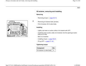
38-35
Speedometer Vehicle Speed Sensor
(VSS) -G22-, removing and installing
Removing
- Disconnect harness connector from
Speedometer Vehicle Speed Sensor (VSS) -
G22-.
- Push retaining bracket of sensor downward, turn
and pull sensor out.
Installing
- Replace sealing rings (arrows).
- Insert O-rings with grease.
- Insert sensor.
- Engage retaining bracket at mounting bracket for flange shaft.
Pa
ge 35 of 44 Oil
pan, oil strainer and valve bod
y, removin
g and installin
g
11/20/2002 htt
p://127.0.0.1:8080/audi/servlet/Dis
play?action=Goto&t
yp
e=re
pair&id=AUDI.B5.AT01.38.1
Page 36 of 44
38-36
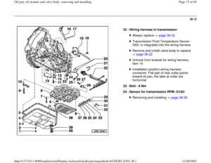
Sensor for transmission RPM -G182-,
removing and installing
Note:
There is a distinction made between two types
of transmission. Transmissions with hydraulic
control E17, the sensor for transmission RPM
(inductive sensor) is secured to bottom of valve
body. Transmissions with hydraulic control
E18/2, the sensor for transmission RPM (hall
effect sensor) is secured to transmission
housing behind valve body.
Information regarding which transmission is
installed can be found in tables page 00
-4
onward.
For transmissions with hydraulic control E17
Removing
- Removing valve body page 38
-22
.
- Turn valve body on its back side and loosen connector at Sensor for
transmission RPM -1-.
Pa
ge 36 of 44 Oil
pan, oil strainer and valve bod
y, removin
g and installin
g
11/20/2002 htt
p://127.0.0.1:8080/audi/servlet/Dis
play?action=Goto&t
yp
e=re
pair&id=AUDI.B5.AT01.38.1
Page 37 of 44
38-37
Installing - Unbolt Sensor for transmission RPM -1- at valve body.
- Tighten Sensor for transmission RPM -1- using spacer sleeves -2-
(height: 20 mm) to 7 Nm.
Installation position: Sensor-side with the connector terminals
points to valve body center.
- Connect connector to Sensor for transmission RPM -1-.
- Installing valve body page 38
-25
.
- Fill up ATF page 37
-140
.
Pa
ge 37 of 44 Oil
pan, oil strainer and valve bod
y, removin
g and installin
g
11/20/2002 htt
p://127.0.0.1:8080/audi/servlet/Dis
play?action=Goto&t
yp
e=re
pair&id=AUDI.B5.AT01.38.1
Page 38 of 44
38-38
For transmissions with hydraulic control
E18/2
Removing
- Removing valve body page 38
-22
.
Installing - Unbolt Sensor for transmission RPM -A- from transmission.
- Bolt on Sensor for transmission RPM -A- at transmission via bolt -B-.
Tightening torque is 9 Nm.
Pa
ge 38 of 44 Oil
pan, oil strainer and valve bod
y, removin
g and installin
g
11/20/2002 htt
p://127.0.0.1:8080/audi/servlet/Dis
play?action=Goto&t
yp
e=re
pair&id=AUDI.B5.AT01.38.1
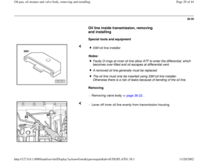
Page 39 of 44
38-39
- Route wire with connector -C- according to illustration, so that the wire
is not pinched when installing the valve body.
- Installing valve body page 38
-25
.
- Fill up ATF page 37
-140
.
Pa
ge 39 of 44 Oil
pan, oil strainer and valve bod
y, removin
g and installin
g
11/20/2002 htt
p://127.0.0.1:8080/audi/servlet/Dis
play?action=Goto&t
yp
e=re
pair&id=AUDI.B5.AT01.38.1
Page 40 of 44
38-40
Transmission Vehicle Speed Sensor
(VSS) -G38-, removing and installing
Removing
- Removing oil pan page 38
-19
.
- Disconnect harness connector from Transmission Vehicle Speed
Sensor (VSS) -G38- (arrow).
Installing - Remove Transmission Vehicle Speed Sensor (VSS) -2-.
- Install and tighten Transmission Vehicle Speed Sensor (VSS) -2- using
spacer sleeve -1- (height: 8 mm) to 6 Nm.
Pa
ge 40 of 44 Oil
pan, oil strainer and valve bod
y, removin
g and installin
g
11/20/2002 htt
p://127.0.0.1:8080/audi/servlet/Dis
play?action=Goto&t
yp
e=re
pair&id=AUDI.B5.AT01.38.1


Switch -F125-, removing and installing
Removing
- Removing left transmission support page 37
-
125
.
- Unbolt Multi-Fun")

 -G22-, removing and installing
Removing
- Disconnect harness connector from
Speedometer Vehicle Speed Sensor (VSS) -
G22-.")

 to 7 Nm.
Installation positio")


 -G38-, removing and installing
Removing
- Removing oil pan page 38
-19
.
- Disconnect harness connector from Transmission")