Page 25 of 44
38-25
All:
- Remove valve body from transmission while
advancing the wiring harness connector.
Note only for Park/Neutral Position (PNP)
Switch -E17-:
Do not place the removed valve body on the
Sensor for transmission RPM at rear of valve
body. Danger of damage.
Installing
- Lightly coat O-rings of wiring harness connector
with ATF.
- Insert wiring harness connector into
transmission housing.
Installation position: Flat part of rear collar
points downward, the tabs at collar are
horizontal
Only for transmission with hydraulic control
E18/2
- Route wire with connector -C- according to illustration, so that the wire
is not pinched when installing the valve body.
Pa
ge 25 of 44 Oil
pan, oil strainer and valve bod
y, removin
g and installin
g
11/20/2002 htt
p://127.0.0.1:8080/audi/servlet/Dis
play?action=Goto&t
yp
e=re
pair&id=AUDI.B5.AT01.38.1
Page 26 of 44
38-26
All:
- Set valve body in place without force while placing bolt of notched disc
-1- into the groove of the selector register -2-.
Notes:
On transmissions with Park/Neutral Position (PNP) Switch -E17-, the bolt
(arrow A) is shorter and thinner than the other bolts. Observe allocation.
The bolt (arrow A) is not installed on transmissions with hydraulic control
E18/2 and can therefore be disregarded. - Next, tighten valve body bolts (arrows) by hand.
- Then tighten valve body bolts from inside out to final tension.
Pa
ge 26 of 44 Oil
pan, oil strainer and valve bod
y, removin
g and installin
g
11/20/2002 htt
p://127.0.0.1:8080/audi/servlet/Dis
play?action=Goto&t
yp
e=re
pair&id=AUDI.B5.AT01.38.1
Page 27 of 44
38-27
Only for transmission with hydraulic control
E18/2
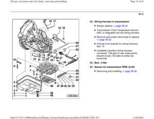
Only for Park/Neutral Position (PNP) Switch -E17- - Pull wiring with connector -B- of Sensor for transmission RPM -G182-
between valve body and wiring harness upward.
- Connect connector -B- to connector -A- at wiring harness.
- Connect connector -C- to Transmission Vehicle Speed Sensor (VSS) -
G38-.
- Connect connector (arrow) to Transmission Vehicle Speed Sensor
(VSS) -G38-.
Pa
ge 27 of 44 Oil
pan, oil strainer and valve bod
y, removin
g and installin
g
11/20/2002 htt
p://127.0.0.1:8080/audi/servlet/Dis
play?action=Goto&t
yp
e=re
pair&id=AUDI.B5.AT01.38.1
Page 28 of 44
38-28
All:
Tightening torque - Connect clip to wiring harness connector (arrow).
- Installing oil strainer page 38
-21
.
- Installing oil pan page 38
-20
.
- Fill up ATF page 37
-140
.
Component
Nm
Valve body to transmission housing (from inside out) 8
Pa
ge 28 of 44 Oil
pan, oil strainer and valve bod
y, removin
g and installin
g
11/20/2002 htt
p://127.0.0.1:8080/audi/servlet/Dis
play?action=Goto&t
yp
e=re
pair&id=AUDI.B5.AT01.38.1
Page 29 of 44
38-29
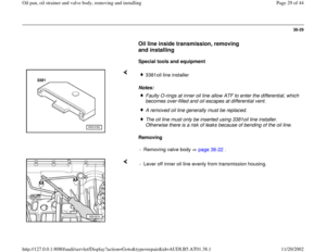
Oil line inside transmission, removing
and installing
Special tools and equipment
Notes:
Removing
3381oil line installer Faulty O-rings at inner oil line allow ATF to enter the differential, which
becomes over-filled and oil escapes at differential vent. A removed oil line generally must be replaced.The oil line must only be inserted using 3381oil line installer.
Otherwise there is a risk of leaks because of bending of the oil line.
- Removing valve body page 38
-22
.
- Lever off inner oil line evenly from transmission housing.
Pa
ge 29 of 44 Oil
pan, oil strainer and valve bod
y, removin
g and installin
g
11/20/2002 htt
p://127.0.0.1:8080/audi/servlet/Dis
play?action=Goto&t
yp
e=re
pair&id=AUDI.B5.AT01.38.1
Page 30 of 44
38-30
Installing
Installation is reverse of removal, noting the
following:
- Replace O-rings.
Notes: - Insert oil line into 3381 oil line installer.
- Drive oil line into transmission housing by lightly tapping on the 3381 oil
line installer up to stop using a plastic mallet.
The open side of 3381 oil line installer faces toward the outer wall of
the transmission. Do not cant oil line. Drive in both line ends uniformly.
- Installing valve body page 38
-25
.
- Fill up ATF page 37
-140
.
- Checking oil level in front final drive page 39
-1 .
Pa
ge 30 of 44 Oil
pan, oil strainer and valve bod
y, removin
g and installin
g
11/20/2002 htt
p://127.0.0.1:8080/audi/servlet/Dis
play?action=Goto&t
yp
e=re
pair&id=AUDI.B5.AT01.38.1
Page 31 of 44
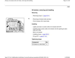
38-31
Shift rod seal, replacing
Special tools and equipment
Removing
3385 sealing ring installer
- Removing left transmission support page 37
-125
.
- Removing Multi-Function Transmission Range (TR) Switch -F125-
page 38
-33
.
- Drive out spring dowel sleeve -1- at lever/shift rod -2- in direction of
travel toward the front (arrow), until the lever/shift rod can be pulled off
the shift rod.
Pa
ge 31 of 44 Oil
pan, oil strainer and valve bod
y, removin
g and installin
g
11/20/2002 htt
p://127.0.0.1:8080/audi/servlet/Dis
play?action=Goto&t
yp
e=re
pair&id=AUDI.B5.AT01.38.1
Page 32 of 44
38-32
Installing - Pierce sealing ring using a small screwdriver and pull out.
- Coat outer circumference and gap between sealing lips with ATF.
Installation position: The open side of the sealing ring faces the
transmission.
- Slide new sealing ring onto 3385 sealing ring installer without canting
and drive in up to stop of pressure piece.
- Installing Multi-function switch page 38
-33
.
- Drive back spring dowel sleeve with transmission not yet removed in
opposite direction through the lever.
- Slide transmission shift lever onto shift rod and drive in spring dowel
sleeve.
- Installing left transmission support page 37
-125
.
Pa
ge 32 of 44 Oil
pan, oil strainer and valve bod
y, removin
g and installin
g
11/20/2002 htt
p://127.0.0.1:8080/audi/servlet/Dis
play?action=Goto&t
yp
e=re
pair&id=AUDI.B5.AT01.38.1


Switch -E17-:
Do not place the r")

 Switch -E17- - Pull wiring with connector -B- of Sensor for transmission RPM -G182-
betwe")
.
- Installing oil strainer page 38
-21
.
- Installing oil pan page 38
-20
.
- Fill up ATF pag")


