Page 25 of 32
13-25
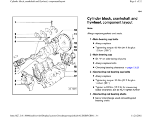
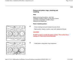
Pistons and piston rings, checking and
installing
Note:
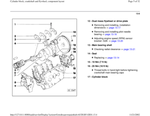
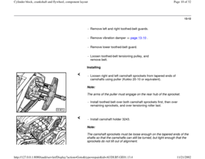
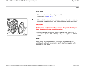
Before removing the pistons, mark their
installation positions clearly on the piston crowns
(as shown in illustration 13-860) using a
waterproof felt-tipped pen.
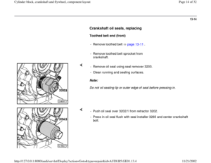
Piston installed position
CAUTION!
Do NOT scratch or scribe the piston surface. This surface has a
coating on it that must not be disturbed. - Arrow marking must point toward oil pump (front).
- Mark position clearly on piston crown with waterproof felt pen.
- Install piston using piston ring compressor.
Pa
ge 25 of 32 C
ylinder block, crankshaft and fl
ywheel, com
ponent la
yout
11/21/2002 htt
p://127.0.0.1:8080/audi/servlet/Dis
play?action=Goto&t
yp
e=re
pair&id=AUDI.B5.GE01.13.4
Page 26 of 32
13-26
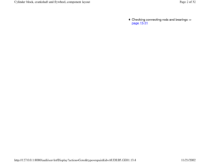
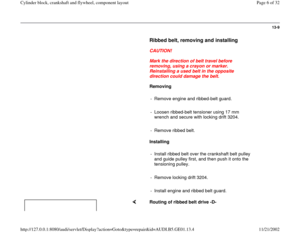
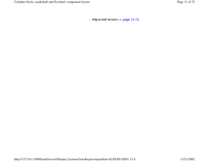
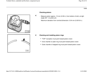
Checking pistons
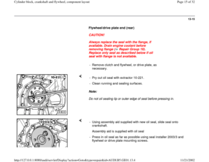
- Measure piston approx. 10 mm (0.39 in.) from bottom of skirt, at right
angle (90 ) to piston pin. Maximum deviation from nominal dimension: 0.04 mm (0.0016 in.)
Checking and installing piston rings
"TOP" inscription must point toward piston crown Inner chamfer on plain ring must point toward piston crown Outer chamfer of stepped ring must point toward piston crown
Pa
ge 26 of 32 C
ylinder block, crankshaft and fl
ywheel, com
ponent la
yout
11/21/2002 htt
p://127.0.0.1:8080/audi/servlet/Dis
play?action=Goto&t
yp
e=re
pair&id=AUDI.B5.GE01.13.4
Page 27 of 32
13-27
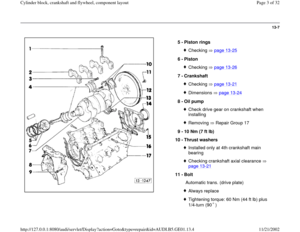
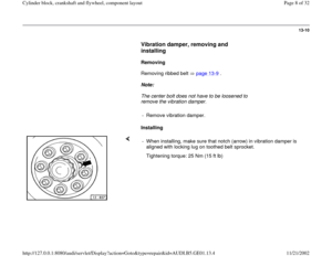
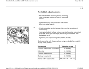
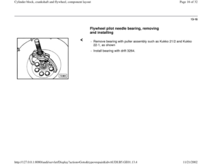
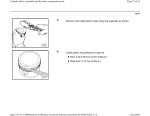
- Remove and install piston rings using ring expander as shown.
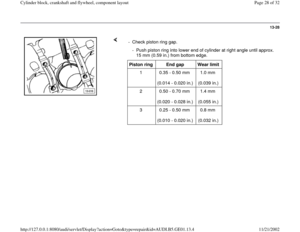
- Check piston ring clearance in groove.
New: 0.02-0.08 mm (0.001-0.003 in.)
Wear limit: 0.10 mm (0.004 in.)
Pa
ge 27 of 32 C
ylinder block, crankshaft and fl
ywheel, com
ponent la
yout
11/21/2002 htt
p://127.0.0.1:8080/audi/servlet/Dis
play?action=Goto&t
yp
e=re
pair&id=AUDI.B5.GE01.13.4
Page 28 of 32
13-28
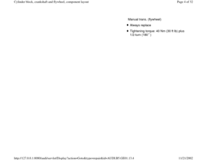
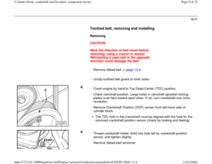
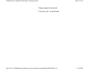
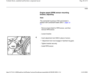
- Check piston ring gap.
- Push piston ring into lower end of cylinder at right angle until approx.
15 mm (0.59 in.) from bottom edge. Piston ring
End gap
Wear limit
1 0.35 - 0.50 mm
(0.014 - 0.020 in.) 1.0 mm
(0.039 in.)
2 0.50 - 0.70 mm
(0.020 - 0.028 in.) 1.4 mm
(0.055 in.)
3 0.25 - 0.50 mm
(0.010 - 0.020 in.) 0.8 mm
(0.032 in.)
Pa
ge 28 of 32 C
ylinder block, crankshaft and fl
ywheel, com
ponent la
yout
11/21/2002 htt
p://127.0.0.1:8080/audi/servlet/Dis
play?action=Goto&t
yp
e=re
pair&id=AUDI.B5.GE01.13.4
Page 29 of 32
13-29
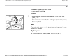
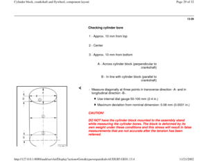
Checking cylinder bore
1 - Approx. 10 mm from top
2 - Center
3 - Approx. 10 mm from bottom
A - Across cylinder block (perpendicular to
crankshaft)
B - In line with cylinder block (parallel to
crankshaft)
CAUTION!
DO NOT have the cylinder block mounted to the assembly stand
while measuring the cylinder bores. The block is deformed by its
own weight under these conditions and this stress will result in false
measurements that are not accurate after the tension has been
relieved. - Measure diagonally at three points in transverse direction -A- and in
longitudinal direction -B-.
Use internal dial gauge 50-100 mm (2-4 in.)
Maximum deviation from nominal dimension: 0.08 mm (0.0031 in.)
Pa
ge 29 of 32 C
ylinder block, crankshaft and fl
ywheel, com
ponent la
yout
11/21/2002 htt
p://127.0.0.1:8080/audi/servlet/Dis
play?action=Goto&t
yp
e=re
pair&id=AUDI.B5.GE01.13.4
Page 30 of 32
13-30
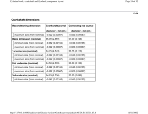
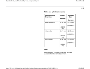
Piston and cylinder dimensions
Reconditioning
dimension Piston
diameter Cylinder
bore
diameter
Basic dimension 82.48 mm
(3.2472
in.) 82.51 mm
(3.2484 in.)
1st oversize 82.74 mm
(3.2575
in.) 82.76 mm
(3.2583 in.)
2nd oversize 82.98 mm
(3.2669
in.) 83.01 mm
(3.2681 in.)
Note:
Only pistons of the "basic dimension" size are
available from the Parts Department.
Pa
ge 30 of 32 C
ylinder block, crankshaft and fl
ywheel, com
ponent la
yout
11/21/2002 htt
p://127.0.0.1:8080/audi/servlet/Dis
play?action=Goto&t
yp
e=re
pair&id=AUDI.B5.GE01.13.4
Page 31 of 32
13-31
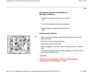
Connecting rods and connecting rod
bearings, checking
Replace connecting rods only as a complete
set.
Do not interchange connecting rod bearings.
Always replace connecting rod bearing cap
bolts.
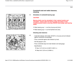
Checking radial clearance
CAUTION!
Do NOT turn the crankshaft or allow it to rotate during the
measurement with Plastigage in place. - Mark connecting rod bearing caps with light punch marks (arrow)
before removing.
- Remove connecting rod bearing caps.
- Clean bearing caps and journals.
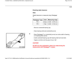
-
Place Plastigage over entire width of bearing journal or in bearing
shell. - Re-install connecting rod bearing cap and tighten to 20 Nm (15 ft lb)
only; do NOT tighten further.
Pa
ge 31 of 32 C
ylinder block, crankshaft and fl
ywheel, com
ponent la
yout
11/21/2002 htt
p://127.0.0.1:8080/audi/servlet/Dis
play?action=Goto&t
yp
e=re
pair&id=AUDI.B5.GE01.13.4
Page 32 of 32
13-32
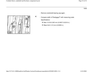
- Remove connecting rod bearing caps again.
-
Compare width of Plastigage with measuring
scale.
Specifications:
New:0.015 to 0.062 mm (0.00059 to
0.00244 in.) Wear
limit: 0.12 mm (0.0047 in.)
Pa
ge 32 of 32 C
ylinder block, crankshaft and fl
ywheel, com
ponent la
yout
11/21/2002 htt
p://127.0.0.1:8080/audi/servlet/Dis
play?action=Goto&t
yp
e=re
pair&id=AUDI.B5.GE01.13.4


 from bottom of skirt, at right
angle (90 ) to piston pin. Maximum deviation from nominal dimension: 0.04 mm (0.0016")

Wear limit: 0.10 mm (0.004 in.)
Pa
g")
 from bottom edge. Piston ring
End gap
Wear limit
1 0.35")

B - In")
 82.51 mm
(3.2484 in.)")

")