Page 715 of 2543

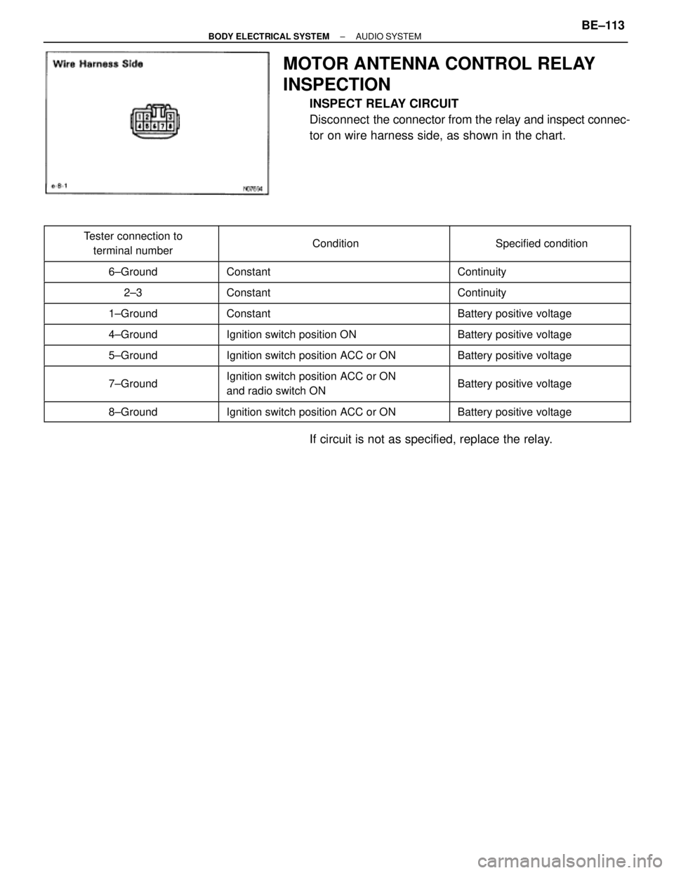
MOTOR ANTENNA CONTROL RELAY
INSPECTION
INSPECT RELAY CIRCUIT
Disconnect the connector from the relay and inspect connec-
tor on wire harness side, as shown in the chart.
����������� �
���������� �����������
Tester connection to
terminal number��������������� �
�������������� ���������������Condition������������ �
����������� ������������Specified condition
����������� �����������6±Ground��������������� ���������������Constant������������ ������������Continuity
����������� �����������2±3��������������� ���������������Constant������������ ������������Continuity����������� �
���������� �����������1±Ground
��������������� �
�������������� ���������������Constant
������������ �
����������� ������������Battery positive voltage
����������� �����������4±Ground��������������� ���������������Ignition switch position ON������������ ������������Battery positive voltage
����������� �����������5±Ground��������������� ���������������Ignition switch position ACC or ON������������ ������������Battery positive voltage
����������� �
���������� �����������7±Ground
��������������� �
�������������� ���������������Ignition switch position ACC or ON
and radio switch ON������������ �
����������� ������������Battery positive voltage
����������� �����������8±Ground��������������� ���������������Ignition switch position ACC or ON������������ ������������Battery positive voltage
If circuit is not as specified, replace the relay.
± BODY ELECTRICAL SYSTEMAUDIO SYSTEMBE±113
Page 805 of 2543
��������������������� ��������������������� ANTENNA MOTOR CONTROL RELAY (Wire Harness Side)���������������� ����������������
��������������������� ��������������������� 1 ± Ground (Constant)���������������� ����������������Battery positive voltage
��������������������� ��������������������� 4 ± Ground (Ignition SW position ON)���������������� ����������������Battery positive voltage��������������������� �
�������������������� ��������������������� 5 ± Ground (Ignition SW position ACC or ON)
���������������� �
��������������� ����������������Battery positive voltage
��������������������� ��������������������� 7 ± Ground (Ignition SW position ACC or ON and radio SW ON)���������������� ����������������Battery positive voltage
��������������������� ��������������������� 8 ± Ground (Ignition SW position ACC or ON)���������������� ����������������Battery positive voltage
± BODY ELECTRICAL SYSTEMSERVICE SPECIFICATIONSBE±203
Page 1185 of 2543
IF VEHICLE IS EQUIPPED WITH MOBILE
COMMUNICATION SYSTEM
For vehicles with mobile communication systems such as
two±way radios and cellular telephones, observe the follow-
ing precautions.
(1) Install the antenna as far as possible away from the ECM,
ECU and sensors of the vehicle's electronic system.
(2) Install the antenna feeder at least 20 cm (7.87 in.) away from
the ECM, ECU and sensors of the vehicle's electronics
systems. For details about ECM, ECU and sensors locations,
refer to the section on the applicable component.
(3) Do not wind the antenna feeder together with the other
wiring. As much as possible, also avoid running the antenna
feeder parallel with other wire harnesses.
(4) Confirm that the antenna and feeder are correctly adjusted.
(5) Do not install powerful mobile communications system. IN±18
± INTRODUCTIONPRECAUTION