Page 1 of 2248
G2M0544
1. Front Catalytic Converter
A: REMOVAL
1) Disconnect front oxygen sensor connector.
B2M0312
2) Lift-up the vehicle.
3) Disconnect rear oxygen sensor connector.
B2M0055
4) Separate center exhaust pipe from rear exhaust pipe.
B2M0054
5) Remove bolts which hold front exhaust pipe onto cylin-
der heads.
B2M0313
6) Remove front exhaust pipe and center exhaust pipe
from hanger bracket.
CAUTION:
Be careful not to pull down front exhaust pipe and
center exhaust pipe.
2
2-1SERVICE PROCEDURE
1. Front Catalytic Converter
Page 2 of 2248
B2M0060
7) Separate front catalytic converter from front exhaust
pipe and center exhaust pipe.
B2M0060
B: INSTALLATION
CAUTION:
Replace gaskets with new ones.
1) Install front catalytic converter to front exhaust pipe and
center exhaust pipe.
Tightening torque:
30±5 N⋅m (3.1±0.5 kg-m, 22.4±3.6 ft-lb)
B2M0313
2) Install front exhaust pipe and center exhaust pipe.
And temporarily tighten bolt which installs center exhaust
pipe to hanger bracket.
B2M0054
3) Tighten bolts which hold front exhaust pipe onto cylin-
der heads.
Tightening torque:
30±5 N⋅m (3.1±0.5 kg-m, 22.4±3.6 ft-lb)
B2M0055
4) Install center exhaust pipe to rear exhaust pipe.
Tightening torque:
18±5 N⋅m (1.8±0.5 kg-m, 13.0±3.6 ft-lb)
3
2-1SERVICE PROCEDURE
1. Front Catalytic Converter
Page 16 of 2248
5) Check idle speed when unloaded. (With headlights,
heater fan, rear defroster, radiator fan, air conditioning, etc.
OFF)
Idle speed (No load and gears in neutral (MT) or N or
P (AT) position):
700±100 rpm
6) Check idle speed when loaded. (Turn air conditioning
switch to“ON”and operate compressor for at least one
minute before measurement.)
Idle speed [A/C“ON”, no load and gears in neutral
(MT) or N or P (AT) position]:
850±50 rpm
CAUTION:
Never rotate idle adjusting screw. If idle speed is out
of specifications, refer to General On-board Diagnosis
Table under “2-7 On-Board Diagnostics II System”.
4
2-2
3. Engine Idle Speed
Page 17 of 2248
 After warming-up the engine, turn ignition switch to
OFF.
2) Make sure that the battery is fully charged.
3) Remove all the spark plugs.
4) Disconnect connector")
4. Engine Compression
A: MEASUREMENT
1) After warming-up the engine, turn ignition switch to
OFF.
2) Make sure that the battery is fully charged.
3) Remove all the spark plugs.
4) Disconnect connectors from fuel injectors.
5) Fully open throttle valve.
6) Check the starter motor for satisfactory performance
and operation.
G2M0098
7) Hold the compression gauge tight against the spark
plug hole.
CAUTION:
When using a screw-in type compression gauge, the
screw (put into cylinder head spark plug hole) should
be less than 18 mm (0.71 in) long.
8) Crank the engine by means of the starter motor, and
read the maximum value on the gauge when the pointer is
steady.
9) Perform at least two measurements per cylinder, and
make sure that the values are correct.
Compression (200—300 rpm and fully open throttle):
Standard
1,079—1,275 kPa
(11.0—13.0 kg/cm
2, 156—185 psi)
Limit
883 kPa (9.0 kg/cm
2, 128 psi)
Difference between cylinders
196 kPa (2.0 kg/cm
2, 28 psi)
5
2-2
4. Engine Compression
Page 21 of 2248
1. Engine
A: SPECIFICATIONS
EngineModel2200 cc
TypeHorizontally opposed, liquid cooled, 4-cylinder, 4-stroke
gasoline engine
Valve arrangement Belt driven, single over-head camshaft, 4-valve/cylinder
Bore x Stroke mm (in) 96.9 x 75.0 (3.815 x 2.953)
Displacement cm
3(cu in) 2,212 (135.0)
Compression ratio9.5
Compression pressure
(at 200 — 300 rpm)kPa (kg/cm
2, psi)1,079 — 1,275
(11.0 — 13.0, 156 — 185)
Number of piston rings Pressure ring: 2, Oil ring: 1
Intake valve timingOpening 1° BTDC
Closing 55° ABDC
Exhaust valve timingOpening 48° BBDC
Closing 12° ATDC
Idling speed
[At neutral position on MT, or
“P” or “N” position on AT] rpm700±100 (No load)
850±50 (A/C switch ON)
Firing order1,3,2,4
Ignition timing BTDC/rpm 14°±8°/700 (MT), 20°±8°/700 (AT)
2
2-3SPECIFICATIONS AND SERVICE DATA
1. Engine
Page 22 of 2248

Belt ten-
sionerSpacer O.D. 16 mm (0.63 in)
Tensioner bush I.D. 16.16 mm (0.6362 in)
Clearance between")
B: SERVICE DATA
Belt
tension
adjusterProtrusion of adjuster rod 15.4—16.4 mm (0.606—0.646 in)
Belt ten-
sionerSpacer O.D. 16 mm (0.63 in)
Tensioner bush I.D. 16.16 mm (0.6362 in)
Clearance between spacer and bushSTD 0.117—0.180 mm (0.0046—0.0071 in)
Limit 0.230 mm (0.0091 in)
Side clearance of spacerSTD 0.37—0.54 mm (0.0146—0.0213 in)
Limit 0.8 mm (0.031 in)
Valve
rocker armClearance between shaft and armSTD 0.020—0.054 mm (0.0008—0.0021 in)
Limit 0.10 mm (0.0039 in)
CamshaftBend limit 0.025 mm (0.0010 in)
Thrust clearanceSTD 0.030—0.260 mm (0.0012—0.0102 in)
Limit 0.35 mm (0.0138 in)
Cam lobe heightIntakeSTD 31.994—32.094 mm (1.2596—1.2635 in)
Limit 31.844 mm (1.2537 in)
ExhaustSTD 32.624—32.724 mm (1.2844—1.2883 in)
Limit 32.474 mm (1.2785 in)
Camshaft journal O.D. RHFront
LHRear 31.935—31.950 mm (1.2573—1.2579 in)
Center Center 37.435—37.450 mm (1.4738—1.4744 in)
Rear Front 37.935—37.950 mm (1.4935—1.4941 in)
Camshaft journal hole
I.D.RHFront
LHRear 32.005—32.025 mm (1.2600—1.2608 in)
Center Center 37.505—37.525 mm (1.4766—1.4774 in)
Rear Front 38.005—38.025 mm (1.4963—1.4970 in)
Oil clearanceSTD 0.055—0.090 mm (0.0022—0.0035 in)
Limit 0.10 mm (0.0039 in)
Cylinder
headSurface warpage limit 0.05 mm (0.0020 in)
Surface grinding limit 0.1 mm (0.004 in)
Standard height 98.3 mm (3.870 in)
Valve setRefacing angle 90°
Contacting widthIntakeSTD 0.7 mm (0.028 in)
Limit 1.4 mm (0.055 in)
ExhaustSTD 1.4 mm (0.055 in)
Limit 1.8 mm (0.071 in)
Valve
guideInner diameter 6.000—6.012 mm (0.2362—0.2367 in)
Protrusion above head 17.5—18.0 mm (0.689—0.709 in)
ValveHead edge thicknessIntakeSTD 1.0 mm (0.039 in)
Limit 0.8 mm (0.031 in)
ExhaustSTD 1.2 mm (0.047 in)
Limit 0.8 mm (0.031 in)
Stem diameterIntake 5.950—5.965 mm (0.2343—0.2348 in)
Exhaust 5.945—5.960 mm (0.2341—0.2346 in)
Stem oil clearanceSTDIntake 0.035—0.062 mm (0.0014—0.0024 in)
Exhaust 0.040—0.067 mm (0.0016—0.0026 in)
Limit—0.15 mm (0.0059 in)
Overall lengthIntake 101.0 mm (3.976 in)
Exhaust 101.2 mm (3.984 in)
STD: Standard I.D.: Inner Diameter O.D.: Outer Diameter
3
2-3SPECIFICATIONS AND SERVICE DATA
1. Engine
Page 23 of 2248

Squareness 2.5°, 1.9 mm (0.075 in)
Tension/spring height174.6—200.1 N
(17.8—20.4 kg, 39.2—45.0 lb)/36.0 mm (1.417 in)
405.0—458.0 N
(41.3—46.7 k")
Valve springFree length 44.05 mm (1.7342 in)
Squareness 2.5°, 1.9 mm (0.075 in)
Tension/spring height174.6—200.1 N
(17.8—20.4 kg, 39.2—45.0 lb)/36.0 mm (1.417 in)
405.0—458.0 N
(41.3—46.7 kg, 91.1—103.0 lb)/28.2 mm (1.110 in)
Cylinder
blockSurface warpage limit (mating with cylinder head) 0.05 mm (0.0020 in)
Surface grinding limit 0.1 mm (0.004 in)
Cylinder bore STDA 96.905—96.915 mm (3.8151—3.8155 in)
B 96.895—96.905 mm (3.8148—3.8151 in)
TaperSTD 0.015 mm (0.0006 in)
Limit 0.050 mm (0.0020 in)
Out-of-roundnessSTD 0.010 mm (0.0004 in)
Limit 0.050 mm (0.0020 in)
Piston clearanceSTD 0.010—0.030 mm (0.0004—0.0012 in)
Limit 0.050 mm (0.0020 in)
Enlarging (boring) limit 0.5 mm (0.020 in)
Piston Outer diameterSTDA 96.885—96.895 mm (3.8144—3.8148 in)
B 96.875—96.885 mm (3.8140—3.8144 in)
0.25 mm (0.0098 in)
OS97.115—97.145 mm (3.8234—3.8246 in)
0.50 mm (0.0197 in)
OS97.365—97.395 mm (3.8333—3.8344 in)
Piston pinStandard clearance between piston
pin and hole in pistonSTD 0.004—0.010 mm (0.0002—0.0004 in)
Limit 0.020 mm (0.0008 in)
Degree of fitPiston pin must be fitted into position with thumb at 20°C
(68°F).
Piston ringPiston ring gapTop ringSTD 0.20—0.35 mm (0.0079—0.0138 in)
Limit 1.0 mm (0.039 in)
Second
ringSTD 0.20—0.50 mm (0.0079—0.0197 in)
Limit 1.0 mm (0.039 in)
Oil ringSTD 0.20—0.70 mm (0.0079—0.0276 in)
Limit 1.5 mm (0.059 in)
Clearance between piston
ring and piston ring grooveTop ringSTD 0.040—0.080mm (0.0016—0.0031 in)
Limit 0.15 mm (0.0059 in)
Second
ringSTD 0.030—0.070 mm (0.0012—0.0028 in)
Limit 0.15 mm (0.0059 in)
Connecting
rodBend twist per 100 mm (3.94 in) in
lengthLimit 0.10 mm (0.0039 in)
Side clearanceSTD 0.070—0.330 mm (0.0028—0.0130 in)
Limit 0.4 mm (0.016 in)
Connecting
rod bearingOil clearanceSTD 0.015—0.045 mm (0.0006—0.0018 in)
Limit 0.05 mm (0.0020 in)
Thickness at center portionSTD 1.492—1.501 mm (0.0587—0.0591 in)
0.03 mm
(0.0012 in)
US1.510—1.513 mm (0.0594—0.0596 in)
0.05 mm
(0.0020 in)
US1.520—1.523 mm (0.0598—0.0600 in)
0.25 mm
(0.0098 in)
US1.620—1.623 mm (0.0638—0.0639 in)
Connecting
rod bushingClearance between piston pin and
bushingSTD 0—0.022 mm (0—0.0009 in)
Limit 0.030 mm (0.0012 in)
STD: Standard OS: Oversize US: Undersize
4
2-3SPECIFICATIONS AND SERVICE DATA
1. Engine
Page 26 of 2248
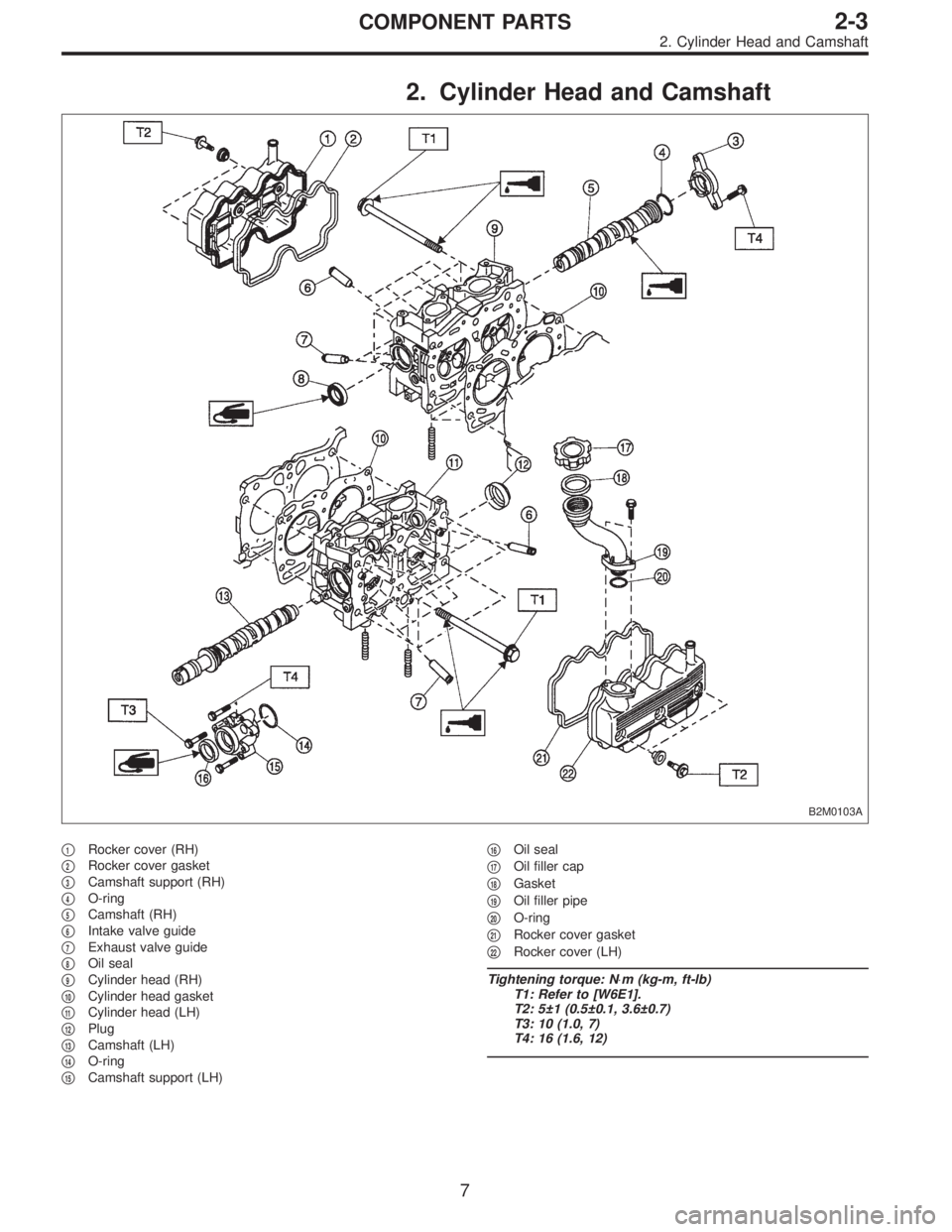
2. Cylinder Head and Camshaft
B2M0103A
�1Rocker cover (RH)
�
2Rocker cover gasket
�
3Camshaft support (RH)
�
4O-ring
�
5Camshaft (RH)
�
6Intake valve guide
�
7Exhaust valve guide
�
8Oil seal
�
9Cylinder head (RH)
�
10Cylinder head gasket
�
11Cylinder head (LH)
�
12Plug
�
13Camshaft (LH)
�
14O-ring
�
15Camshaft support (LH)�
16Oil seal
�
17Oil filler cap
�
18Gasket
�
19Oil filler pipe
�
20O-ring
�
21Rocker cover gasket
�
22Rocker cover (LH)
Tightening torque: N⋅m (kg-m, ft-lb)
T1: Refer to [W6E1].
T2: 5±1 (0.5±0.1, 3.6±0.7)
T3: 10 (1.0, 7)
T4: 16 (1.6, 12)
7
2-3COMPONENT PARTS
2. Cylinder Head and Camshaft
 Disconnect front oxygen sensor connector.
B2M0312
2) Lift-up the vehicle.
3) Disconnect rear oxygen sensor connector.
B2M0055
4) Separate center exha")
 Separate front catalytic converter from front exhaust
pipe and center exhaust pipe.
B2M0060
B: INSTALLATION
CAUTION:
Replace gaskets with new ones.
1) Install front catalytic converter to f")
 Check idle speed when unloaded. (With headlights,
heater fan, rear defroster, radiator fan, air conditioning, etc.
OFF)
Idle speed (No load and gears in neutral (MT) or N or
P (AT) position):
700±")