Page 346 of 2248

1. Automatic Transmission and
Differential
A: SPECIFICATIONS
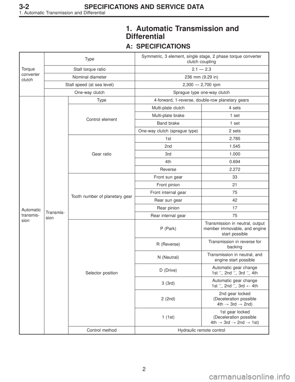
Torque
converter
clutchTypeSymmetric, 3 element, single stage, 2 phase torque converter
clutch coupling
Stall torque ratio 2.1 — 2.3
Nominal diameter 236 mm (9.29 in)
Stall speed (at sea level) 2,300 — 2,700 rpm
One-way clutch Sprague type one-way clutch
Automatic
transmis-
sionTransmis-
sionType 4-forward, 1-reverse, double-row planetary gears
Control elementMulti-plate clutch 4 sets
Multi-plate brake 1 set
Band brake 1 set
One-way clutch (sprague type) 2 sets
Gear ratio1st 2.785
2nd 1.545
3rd 1.000
4th 0.694
Reverse 2.272
Tooth number of planetary gearFront sun gear 33
Front pinion 21
Front internal gear 75
Rear sun gear 42
Rear pinion 17
Rear internal gear 75
Selector positionP (Park)Transmission in neutral, output
member immovable, and engine
start possible
R (Reverse)Transmission in reverse for
backing
N (Neutral)Transmission in neutral, and
engine start possible
D (Drive)Automatic gear change
1st
+
,2nd+
,3rd+
,4th
3 (3rd)Automatic gear change
1st
+
,2nd+
,3rd+4th
2 (2nd)2nd gear locked
(Deceleration possible
4th,3rd,2nd)
1 (1st)1st gear locked
(Deceleration possible
4th,3rd,2nd,1st)
Control method Hydraulic remote control
2
3-2SPECIFICATIONS AND SERVICE DATA
1. Automatic Transmission and Differential
Page 969 of 2248
B6M0146
13. Door Mirror
A: REMOVAL
1) Remove the gusset cover.
B5M0296
2) Remove inner remote control switch cover.
B5M0297
3) Remove inner remote control switch.
4) Remove front door trim.
B5M0298A
5) Disconnect the door mirror connector.
6) Remove the door mirror installation screws.
B: INSTALLATION
Installation is in the reverse order of removal.
49
5-1SERVICE PROCEDURE
13. Door Mirror
Page 983 of 2248
6. Door Lock Assembly
1. FRONT DOOR
B5M0057A
�1Holder remote
�
2Inner remote ASSY
�
3Door outer handle
�
4Striker
�
5Door latch
�
6Switch ASSY
�
7Auto-door lock actuator
�
8Bell crank
�
9Rod holder
Tightening torque: N⋅m (kg-m, ft-lb)
T1: 6.4±2.0 (0.65±0.2, 4.7±1.4)
T2: 7.4±2.0 (0.75±0.2, 5.4±1.4)
T3: 14±4 (1.4±0.4, 10.1±2.9)
8
5-2COMPONENT PARTS
6. Door Lock Assembly
Page 984 of 2248
2. REAR DOOR
B5M0058A
�1Door outer handle
�
2Door latch
�
3Door lock actuator
�
4Striker
�
5Rod holder
�
6Holder remote
�
7Inner remote ASSY
Tightening torque: N⋅m (kg-m, ft-lb)
T1: 6.4±2.0 (0.65±0.2, 4.7±1.4)
T2: 7.4±2.0 (0.75±0.2, 5.4±1.4)
T3: 14±4 (1.4±0.4, 10.1±2.9)
9
5-2COMPONENT PARTS
6. Door Lock Assembly
Page 987 of 2248

1. Procedure Chart for Removing and
Installing Door and Related Parts
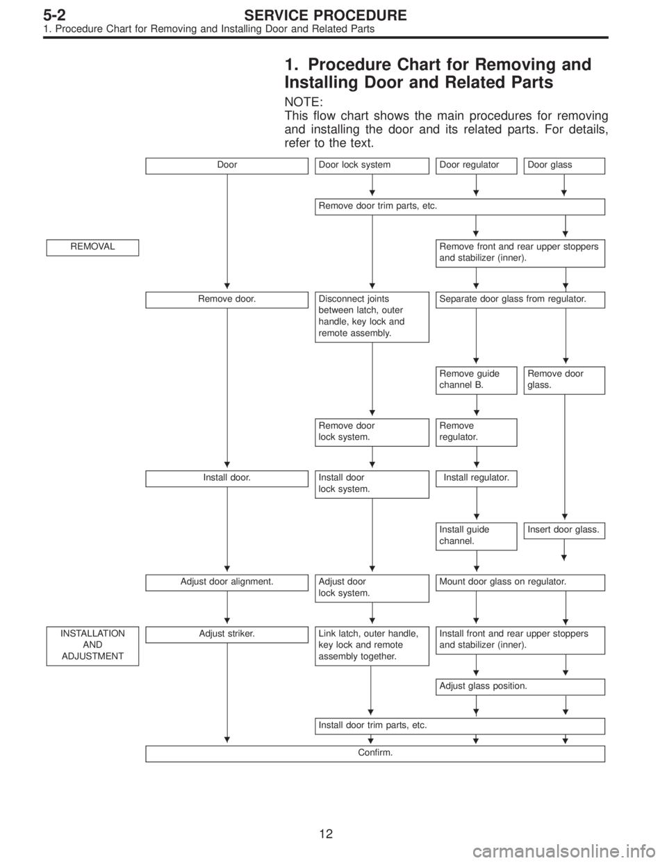
NOTE:
This flow chart shows the main procedures for removing
and installing the door and its related parts. For details,
refer to the text.
DoorDoor lock systemDoor regulator
�
Door glass
�
Remove door trim parts, etc.
�
REMOVALRemove front and rear upper stoppers
and stabilizer (inner).
�
Remove door.Disconnect joints
between latch, outer
handle, key lock and
remote assembly.Separate door glass from regulator.
Remove guide
channel B.Remove door
glass.
Remove door
lock system.Remove
regulator.
Install door.Install door
lock system.Install regulator.
Install guide
channel.Insert door glass.
�
Adjust door alignment.Adjust door
lock system.Mount door glass on regulator.
�
INSTALLATION
AND
ADJUSTMENTAdjust striker.Link latch, outer handle,
key lock and remote
assembly together.Install front and rear upper stoppers
and stabilizer (inner).
�
Adjust glass position.
��
Install door trim parts, etc.
���
Confirm.
�
�
���
��
��
���
��
���
���
�
�
�
12
5-2SERVICE PROCEDURE
1. Procedure Chart for Removing and Installing Door and Related Parts
Page 989 of 2248

G5M0390
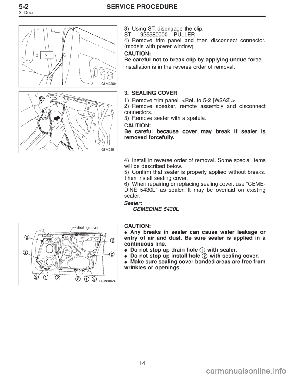
3) Using ST, disengage the clip.
ST 925580000 PULLER
4) Remove trim panel and then disconnect connector.
(models with power window)
CAUTION:
Be careful not to break clip by applying undue force.
Installation is in the reverse order of removal.
G5M0391
3. SEALING COVER
1) Remove trim panel.
2) Remove speaker, remote assembly and disconnect
connectors.
3) Remove sealer with a spatula.
CAUTION:
Be careful because cover may break if sealer is
removed forcefully.
4) Install in reverse order of removal. Some special items
will be described below.
5) Confirm that sealer is properly applied without breaks.
Then install sealing cover.
6) When repairing or replacing sealing cover, use “CEME-
DINE 5430L” as sealer. It may be overlaid on existing
sealer.
Sealer:
CEMEDINE 5430L
B5M0062A
CAUTION:
�Any breaks in sealer can cause water leakage or
entry of air and dust. Be sure sealer is applied in a
continuous line.
�Do not stop up drain hole�
1with sealer.
�Do not stop up install hole�
2with sealing cover.
�Make sure sealing cover bonded areas are free from
wrinkles or openings.
14
5-2SERVICE PROCEDURE
2. Door
Page 990 of 2248
G5M0392
4. CHECKER
1) Remove trim panel.
2) Remove sealing cover.
3) Apply a cloth to door and body to prevent damaging
them, and remove checker pin by driving it upward.
CAUTION:
Be careful not to damage door and body.
4) Completely close door glass.
5) Loosen two nuts securing checker, and take out
checker through access hole in underside.
Installation should be made in the reverse order of
removal.
Tightening torque:
7.4±2.0 N⋅m (0.75±0.2 kg-m, 5.4±1.4 ft-lb)
5. DOOR GLASS
1) Remove trim panel.
2) Remove sealing cover.
3) Disconnect door mirror connector and then remove
gusset�
1.
4) Remove inner remote.
B5M0063A
5) Remove inner stabilizer�1.
B5M0064A
6) Remove nut and then separate glass holder�1from
guide channel A�
2.
NOTE:
When removing nut, move door window lower glass con-
necting section to service hole of door panel.
7) Remove window glass upward.
CAUTION:
After removing window glass, do not move regulator.
15
5-2SERVICE PROCEDURE
2. Door
Page 991 of 2248
B5M0065
8) Remove regulator installing bolt and guide channel B
installing nut.
9) Remove regulator through lower service hole of door
panel.
10) Installation is in the reverse order of removal.
G5M0394
6. INNER REMOTE
1) Remove trim panel.
2) Remove sealing cover.
3) Disconnect joints of two rods.
4) Unlatch rod holder.
B5M0066A
5) Remove remote holder�1and then remove inner
remote assembly�
2.
6) Installation is in the reverse order of removal. Some
special items will be described below.
7) After passing two rods through holder, attach remote
assembly to inner panel.
8) Latch rod holder.
B5M0330A
9) Lock the door and then loosen bolt�1.
10) Lower bell-crank�
2and then tighten bolt�2.
NOTE:
If rear door is equipped with child safety lock, check that
child lock lever moves without dragging.
16
5-2SERVICE PROCEDURE
2. Door