1995 JEEP YJ oil type
[x] Cancel search: oil typePage 1767 of 2158
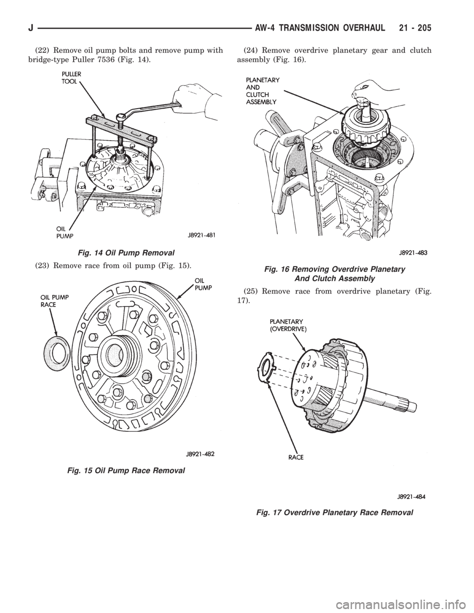
(22) Remove oil pump bolts and remove pump with
bridge-type Puller 7536 (Fig. 14).
(23) Remove race from oil pump (Fig. 15).(24) Remove overdrive planetary gear and clutch
assembly (Fig. 16).
(25) Remove race from overdrive planetary (Fig.
17).
Fig. 14 Oil Pump Removal
Fig. 15 Oil Pump Race Removal
Fig. 16 Removing Overdrive Planetary
And Clutch Assembly
Fig. 17 Overdrive Planetary Race Removal
JAW-4 TRANSMISSION OVERHAUL 21 - 205
Page 1908 of 2158
TIRE CHAINS
Tire snow chains may be used on certain models.
Refer to Owner's Manual for more information.
CLEANING OF TIRES
Steam cleaning may be used for cleaning.
DO NOT use gasoline or wire brush for cleaning.
DO NOT use mineral oil or an oil-based solvent.
PRESSURE GAUGES
High-quality, dial-type, air-pressure gauges are rec-
ommended. After checking with the gauge, replace
valve cap and finger tight.
TIRE INFLATION PRESSURES
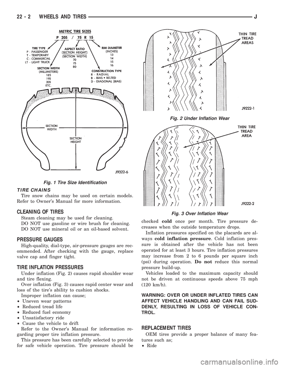
Under inflation (Fig. 2) causes rapid shoulder wear
and tire flexing.
Over inflation (Fig. 3) causes rapid center wear and
loss of the tire's ability to cushion shocks.
Improper inflation can cause;
²Uneven wear patterns
²Reduced tread life
²Reduced fuel economy
²Unsatisfactory ride
²Cause the vehicle to drift
Refer to the Owner's Manual for information re-
garding proper tire inflation pressure.
This pressure has been carefully selected to provide
for safe vehicle operation. Tire pressure should becheckedcoldonce per month. Tire pressure de-
creases when the outside temperature drops.
Inflation pressures specified on the placards are al-
wayscold inflation pressure. Cold inflation pres-
sure is obtained after the vehicle has not been
operated for at least 3 hours. Tire inflation pressures
may increase from 2 to 6 pounds per square inch
(psi) during operation.Do notreduce this normal
pressure build-up.
Vehicles loaded to the maximum capacity should
not be driven at continuous speeds above 75 mph
(120 km/h).
WARNING: OVER OR UNDER INFLATED TIRES CAN
AFFECT VEHICLE HANDLING AND CAN FAIL SUD-
DENLY, RESULTING IN LOSS OF VEHICLE CON-
TROL.
REPLACEMENT TIRES
OEM tires provide a proper balance of many fea-
tures such as;
²Ride
Fig. 1 Tire Size Identification
Fig. 2 Under Inflation Wear
Fig. 3 Over Inflation Wear
22 - 2 WHEELS AND TIRESJ
Page 2087 of 2158
EVAPORATOR COIL:The coil is located in the
A/C housing. Its function is to remove heat and de-
humidify the air before it enters the vehicle.
FIN SENSING CYCLING CLUTCH SWITCH:
The switch is attached to the evaporator coil with the
temperature sensing probe inserted into the coil fins.
This switch controls evaporator temperature and pre-
vents condensate water on the evaporator coil from
freezing. It does this by sending signals to the Pow-
ertrain Control Module (PCM) to cycling the com-
pressor clutch on and off. This switch is used onXJ
only.
FILTER-DRIER:The drier is used to remove any
traces of moisture from the refrigerant system. A
sight glass is located on top of the filter drier. It is
used as a diagnostic tool to observe refrigerant flow.
HIGH PRESSURE RELIEF VALVE:The valve is
located on the filter drier. The valve is used to pre-
vent excessive high pressure build of 3445 to 4135
kPa (500 to 600 psi) and above. This prevents dam-
age to the compressor and other system components.
LOW-PRESSURE HIGH-PRESSURE CUT-OFF
SWITCH:The switch is located on the filter drier
and is wired in series with compressor clutch. When
the pressure drops down to 193 kPa (28 psi) the
switch interrupts the power to the compressor clutch.
When the pressure increases above 3100 to 3375 kPa
(450 to 490 psi) the switch interrupts the power to
the compressor clutch.
THERMOSTAT:The thermostat is located in the
evaporator housing. The thermostat temperature
sensing probe is inserted into the evaporator coil. Its
function is to cycles the compressor clutch on and off.
This switch controls temperature and prevents con-
densate water on the evaporator coil from freezing.
The thermostat is used on theYJonly.
REFRIGERANT LINES:The lines are used to
carry the refrigerant between the various system
components.
SERVICE PORTS:The high pressure service port
is located on the discharge line near the compressor.
The low pressure service port is located on the suc-
tion line near the compressor. These ports are used
to attach A/C gauges. After servicing the refrigerant
system, always install service port caps.
REFRIGERANT
XJ and YJ vehicles use a new type of refrigerant
called R-134a. It is a non-toxic, non-flammable, clear
color-less liquified gas.
R-134a refrigerant is not compatible with R-12 re-
frigerant. A small amount of R-12 in a R-134a system
will cause compressor failure, oil sludge or poor air
conditioning performance.R-134a refrigerant requires a special type of com-
pressor oil (SP20 PAG). When adding oil, make sure
that it is designed to be used in a R-134a system and
the SD7H15 compressor.
Service ports have been designed to ensure that
the system is not accidentally filled with R-12 refrig-
erant.
REFRIGERANT EQUIPMENT
WARNING: EYE PROTECTION MUST BE USED
WHEN SERVICING AN AIR CONDITIONING REFRIG-
ERANT SYSTEM. TURN OFF (ROTATE CLOCKWISE)
ALL VALVES ON THE EQUIPMENT BEING USED
BEFORE PROCEEDING WITH THIS OPERATION.
PERSONNEL INJURY CAN RESULT.
Chrysler Corporation recommends a (R-134a) recy-
cling device that meets SAE standard J2210 be used
when servicing the refrigerant system. Contact an
automotive service equipment supplier for refrigerant
recycling equipment that is available in your area.
Refer to the operating instructions provided with the
recycling equipment for proper operation.
MANIFOLD GAUGE SET
CAUTION: DO NOT use an R-12 manifold gauge set
on an R-134a system. The refrigerants are not com-
patible and system damage will result.
A manifold gauge set (Fig. 1) may be needed in
conjunction with the charging and or recovery/recy-
cling device. The service hoses on the gauge set being
used should have manual (turn wheel) or automatic
back flow valves at the service port connector ends.
This will prevent refrigerant from being release into
the atmosphere.
LOW PRESSURE GAUGE HOSE
The low pressure hose (BLUE with BLACK STRIP)
should be attached to the charging/service port. This
port is located at the right front of the engine com-
partment in the condenser-to-evaporator line.
HIGH PRESSURE GAUGE HOSE
The high pressure hose (RED with BLACK STRIP)
should be attached to the discharge/service port. This
port is located on the compressor plumbing or mani-
fold.
RECOVERY/RECYCLING/EVACUATION/
CHARGING HOSE
The center manifold hose (YELLOW or WHITE
with BLACK STRIP) is used to recover, evacuate and
charge the refrigerant system. When the low or high
pressure valves on the manifold gauge set are
opened, the refrigerant in the system will escape
through this hose.
JHEATING AND AIR CONDITIONING 24 - 7
Page 2089 of 2158
WARNINGS, CAUTIONS AND SERVICE PRECAUTIONS
WARNINGS
WARNING: THE AIR CONDITIONING SYSTEM CON-
TAINS REFRIGERANT UNDER HIGH PRESSURE.
SEVERE PERSONAL INJURY MAY RESULT FROM
IMPROPER SERVICE PROCEDURES. REPAIRS
SHOULD ONLY BE PERFORMED BY QUALIFIED
SERVICE PERSONNEL.
WARNING: AVOID BREATHING A/C REFRIGERANT
AND LUBRICANT VAPOR OR MIST. EXPOSURE MAY
IRRITATE EYES, NOSE AND/OR THROAT. WEAR
EYE PROTECTION WHEN SERVICING THE AIR
CONDITIONING REFRIGERANT SYSTEM. SERIOUS
EYE INJURY CAN RESULT FROM EYE CONTACT
WITH REFRIGERANT. IF EYE CONTACT IS MADE,
SEEK MEDICAL ATTENTION IMMEDIATELY.
WARNING: DO NOT EXPOSE REFRIGERANT TO
OPEN FLAME. POISONOUS GAS IS CREATED
WHEN REFRIGERANT IS BURNED. AN ELEC-
TRONIC TYPE LEAK DETECTOR IS RECOM-
MENDED.
WARNING: IF ACCIDENTAL SYSTEM DISCHARGE
OCCURS, VENTILATE THE WORK AREA BEFORE
RESUMING SERVICE. LARGE AMOUNTS OF RE-
FRIGERANT RELEASED IN A CLOSED WORK AREA
WILL DISPLACE THE OXYGEN AND CAUSE SUFFO-
CATION.
WARNING: THE EVAPORATION RATE OF (R-134A)
REFRIGERANT AT AVERAGE TEMPERATURE AND
ALTITUDE IS EXTREMELY HIGH. AS A RESULT,
ANYTHING THAT COMES IN CONTACT WITH THE
REFRIGERANT WILL FREEZE. ALWAYS PROTECT
SKIN OR DELICATE OBJECTS FROM DIRECT CON-
TACT WITH REFRIGERANT.
WARNING: R-134A SERVICE EQUIPMENT OR VEHI-
CLE A/C SYSTEM SHOULD NOT BE PRESSURE
TESTED OR LEAK TESTED WITH COMPRESSED
AIR. SOME MIXTURES OF AIR AND R-134A HAVE
BEEN SHOWN TO BE COMBUSTIBLE AT ELEVATED
PRESSURES. THESE MIXTURES ARE POTENTIALLY
DANGEROUS AND MAY RESULT IN FIRE OR EX-
PLOSION CAUSING INJURY OR PROPERTY DAM-
AGE.
CAUTIONS
CAUTION: Liquid refrigerant is corrosive to metal
surfaces. Follow the operating instructions supplied
with equipment being used.
CAUTION: DO NOT use R-12 equipment or parts on
the R-134a system. Damage to the system will re-
sult.
CAUTION: Never add R-12 to a system designed to
use R-134a. Damage to the system will result.
CAUTION: R-12 compressor oil can not be mixed
with the R-134a compressor oil. They ARE NOT
compatible.
CAUTION: Do not over charge refrigerant system.
This will cause excessive compressor head pres-
sure and can cause noise and system failure.
SERVICE PRECAUTIONS
Recover the refrigerant before opening any fitting
or connection. Open fittings with caution even after
the system has been discharged. Never open or
loosen a connection before recovering the refrigerant.
The A/C system must always be evacuated before
charging.
DO NOT open the refrigerant system or uncap a
replacement component until you are ready to service
the system. This will prevent contamination in the
system.
Before disconnecting a component clean the outside
of the fittings thoroughly to prevent contamination
entering the system.
Immediately after disconnecting a component from
the system, seal the open fittings with a cap or plug.
Before connecting an open fitting always install a
new seal/gasket. Coat the fitting and seal with clean
refrigerant oil before connecting.
When installing a refrigerant line avoid sharp
bends. Position the lines away from the exhaust or
any sharp edges which may chafe the line.
Tighten fittings only to the specified torque. The
aluminum fittings used in the A/C system will not
tolerate over tightening.
When disconnecting a fitting use a wrench on both
halves of the fitting. This will prevent twisting of the
refrigerant lines or tubes.
Refrigerant oil absorbs moisture from the atmo-
sphere if left uncapped. DO NOT open a container of
JHEATING AND AIR CONDITIONING 24 - 9
Page 2092 of 2158
REFRIGERANT OIL
It is important to have the correct amount of oil in
the A/C system. This will ensure proper lubrication of
the compressor. Too little oil will result in damage to
the compressor. Too much oil will reduce the cooling
capacity of the system.
The oil used in the SD7H15 compressor is a poly-
alkylene glycol synthetic oil SP-20 PAG, wax-free re-
frigerant oil. Only refrigerant oil of the same type
should be used to service the system. Do not use any
other oil. The oil container should be kept tightly
capped until it is ready for use and then capped after
use to prevent contamination. Refrigerant oil will
quickly absorb any moisture it comes in contact with.
OIL LEVEL CHECK
It will not be necessary to check oil level in the
compressor or to add oil unless there has been an oil
loss. This may be due to a rupture or leak from a
line, shaft seal, evaporator or condenser. Oil loss at a
leak point will be evident by the presence of a wet,
shiny surface around the leak.
When an A/C system is assembled at the factory,
all components (except the compressor) are refriger-
ant oil free. After the system has been charged and
operated, the oil in the compressor is dispersed
through the system. The receiver-drier, evaporator,
condenser and compressor will retain a significant
amount of oil.
Refrigerant oil must be added when a receiver-
drier, evaporator, condenser or compressor are re-
placed. When the compressor is replaced, the oil
must be drained from the replaced compressor and
measured. Drain all the oil from the new compressor.
Add back into the new compressor the amount of oil
that was drained out of the old compressor.
Add an additional 30 ml (1 fluid oz.) of com-
pressor oil to the system when a receiver-drier,
condenser or evaporator is replaced.
AIR CONDITIONING PERFORMANCE TESTS
Humidity has an important bearing on the temper-
ature of the air delivered to the vehicle's interior. It
is important to understand the effect humidity has
on the performance of the system. When humidity is
high, the evaporator has to perform a double duty. It
must lower the air temperature and the temperature
of the moisture carried in the air. Condensing the
moisture in the air transfers a great deal of heat en-
ergy into the evaporator fins and tubing. This re-
duces the amount of heat the evaporator can absorb
from the air. High humidity greatly reduces the evap-
orator's ability to lower the temperature of the air.Evaporator capacity used to reduce the amount of
moisture in the air is not wasted. Wringing some of
the moisture out of the air entering the vehicle adds
to the comfort of the passengers. However, an owner
may expect too much from their air conditioning sys-
tem on humid days. A performance test is the best
way to determine whether or not the system is per-
forming up to standard. This test also provides valu-
able clues to the possible cause of trouble.
Air temperature in test room must be 21ÉC (70ÉF)
minimum for this test.
(1) Connect a Tachometer and manifold gauge set.
(2) Set A/C controls to Max A/C, temperature lever
on full cool and blower on high.
(3) Start engine and adjust idle to 1,000 RPM with
A/C clutch engaged.
(4) Engine should be warmed up with doors, win-
dows and hood closed.
(5) Insert a thermometer in the left center A/C out-
let. Operate the A/C and engine for 5 minutes. The
A/C clutch may cycle depending on ambient temper-
atures.
(6) After 5 minutes note the discharge air temper-
ature. If the clutch cycles, take the reading before
the clutch disengages.
(7) On LHD XJ vehicles open the hood and discon-
nect vacuum line going to the heater water control
valve. Observe the valve arm for movement as the
line is disconnected. Plug the vacuum line to prevent
leakage. If it does not move repair vacuum circuit.
(8) Operate the A/C for 2 more minutes and take
the discharge air temperature reading again. On XJ
vehicles if the temperature increased by more than
2ÉC (5ÉF) check the blend air door cable for correct
operation.
(9) Compare the discharge air temperature to the
A/C Performance (Temperature and Pressure) Chart.
If the discharge air temperature is high, refer to Re-
frigerant Leak Testing and Refrigerant System Diag-
nosis Chart.
(10) Compare the compressor discharge and suc-
tion pressures to the A/C Performance (Temperature
and Pressure) Chart. If the compressor discharge or
suction pressure is not normal, check the operation of
the refrigerant system. Refer to Refrigerant System
Diagnosis Chart.
If pressures are abnormal, refer to the Pressure
and Performance Diagnosis Charts.
The following chart have been developed for quick
reference.
24 - 12 HEATING AND AIR CONDITIONINGJ
Page 2101 of 2158
(9) Remove the screw and retainer from coil lead
wire on compressor front housing (Fig. 9).
(10) Remove snap ring from compressor hub and
remove field coil (Fig. 10).INSTALLATION
(1) Install field coil and snap ring.
(2) Install coil harness retaining clip on compres-
sor and tighten the retaining screw.
(3) Align rotor assembly squarely on the front
housing hub.
(4) Install pulley bearing assembly with Installer
6871 (Fig. 11).
Thread Installer on shaft then turn nut until pul-
ley assembly is seated.
(5) Install external front housing snap ring with
spread type snap ring pliers.
(6) Install key and original clutch shims on com-
pressor shaft.
(7) Install clutch plate with driver 6463 (Fig. 12).
Install shaft nut and tighten to 14.4 Nzm (10.5 ft.
lbs.) torque.
Fig. 9 Coil Lead Wire
Fig. 10 Snap Ring and Field Coil Removal
Fig. 11 Pulley Installer
Fig. 12 Clutch Plate Driver
JHEATING AND AIR CONDITIONING 24 - 21
Page 2155 of 2158
TROUBLESHOOTING TOOLS; WIRING
DIAGRAMSÐGENERAL INFORMATION
(XJ)...............................8W-4
TROUBLESHOOTING WIRING
PROBLEMS; WIRING DIAGRAMSÐ
GENERAL INFORMATION (XJ)...........8W-5
TUBE AXLE (2WD), MODEL 30 AXLE......2-22
TUBE CAP, FUEL TANK FILLER;
EMISSION CONTROL SYSTEMS......25-4,25-7
TUBE CAP, FUEL TANK FILLER; FUEL
SYSTEM............................14-13
TUBE, NO-LEAD FUEL TANK FILLER......14-13
TUBES/LINES/HOSES AND CLAMPS,
FUEL..........................14-62,14-9
TURN RELAY, LEFT; TRAILER TOW (XJ) . 8W-54-1
TURN RELAY, LEFT; TRAILER TOW
(XJ-RHD).........................8W-54-1
TURN RELAY, RIGHT; TRAILER TOW
(XJ).............................8W-54-1
TURN RELAY, RIGHT; TRAILER TOW
(XJ-RHD).........................8W-54-1
TURN SIGNAL INDICATOR LAMPS;
INSTRUMENT CLUSTER (XJ).........8W-40-2
TURN SIGNAL INDICATOR LAMPS;
INSTRUMENT CLUSTER (XJ-RHD).....8W-40-2
TURN SIGNAL RELAY; TURN SIGNALS
(XJ-RHD).........................8W-52-1
TURN SIGNAL SYSTEM.................8J-1
TURN SIGNAL SYSTEM - YJ.............8J-3
TURN SIGNAL/HAZARD WARNING
SWITCH REMOVE/INSTALL - YJ..........8J-5
TURN SIGNAL/HAZARD WARNING
SYSTEM - XJ..........................8J-3
TURN SIGNALS; TURN SIGNALS (YJ) . . 8W-52-1
TURN SIGNAL/TAIL LAMP BULB
REPLACEMENTÐXJ, BACK-UP/REAR.....8L-12
TURN SIGNAL/TAIL LAMP BULB
REPLACEMENTÐYJ, BACK-UP/REAR.....8L-28
TWO-WHEEL-DRIVE VEHICLE TOWINGÐ
XJ .................................0-11
U-JOINTS, PROPELLER SHAFTS.........16-15
UNBALANCE.........................16-3
UNDERHOOD LAMP; INTERIOR
LIGHTING (XJ)....................8W-44-2
UNDERHOOD LAMP; INTERIOR
LIGHTING (XJ-RHD)................8W-44-1
UNDERHOOD LAMP; INTERIOR
LIGHTING (YJ)....................8W-44-1
UNDERHOOD LAMP BULB
REPLACEMENTÐXJ..................8L-13
UNDERHOOD LAMP BULB
REPLACEMENTÐYJ..................8L-29
UNDERHOOD LAMP REPLACEMENTÐXJ . . 8L-13
UNDERHOOD LAMP REPLACEMENTÐYJ . . 8L-29
UNDERHOOD LAMP SERVICE
INFORMATIONÐXJ...................8L-12
UNDERHOOD LAMP SERVICE
INFORMATIONÐYJ...................8L-28
UNIT (ECU), ELECTRONIC CONTROL......5-34
UNIT, FUEL GAUGE SENDING...........14-16
UNIT (HCU), HYDRAULIC CONTROL.......5-33
UNIT, HYDRAULIC CONTROL; ANTI-LOCK
BRAKES (XJ)......................8W-32-2
UNIT, HYDRAULIC CONTROL; ANTI-LOCK
BRAKES (XJ-RHD).................8W-32-2
UNIT, HYDRAULIC CONTROL; ANTI-LOCK
BRAKES (YJ)......................8W-32-2
UNIVERSAL JOINT ANGLE
MEASUREMENT.......................16-4
UNIVERSAL JOINT REPLACEMENT.......16-10
UNIVERSAL JOINTS...................16-2
UNLOCK RELAY; POWER DOOR LOCKS
(XJ).............................8W-61-1
UNLOCK RELAY; POWER DOOR LOCKS
(XJ-RHD).........................8W-61-1
UPPER SUSPENSION ARM..............2-12
UPSHIFT LAMP; FUEL/IGNITION (XJ) . . . 8W-30-5
UP-SHIFT LAMP; INSTRUMENT CLUSTER
(YJ)
.............................8W-40-2
UPSHIFT LAMP; TRANSMISSION
CONTROLS (XJ)
...................8W-31-1
UPSHIFT LAMP; TRANSMISSION
CONTROLS (YJ)
...................8W-31-1
UP-SHIFT LAMP, MANUAL
TRANSMISSION; INSTRUMENT
CLUSTER (XJ)
.....................8W-40-2
USAGE, INSTALLATION METHODS AND
PARTS
...............................6-4USAGE STATEMENT, FUEL...............14-1
USAGE STATEMENTÐGAS ENGINES,
FUEL...............................0-19
USE THIS GROUP, HOW TO; WIRING
DIAGRAMS (XJ)......................8W-1
USE THIS GROUP, HOW TO; WIRING
DIAGRAMS (XJ-RHD)..................8W-1
USE THIS GROUP, HOW TO; WIRING
DIAGRAMS (YJ)......................8W-1
USING ALIGNMENT SCREENÐXJ,
HEADLAMP/FOG LAMP ADJUSTMENT.....8L-7
USING ALIGNMENT SCREENÐYJ,
HEADLAMP/FOG LAMP ADJUSTMENT....8L-23
USING ON-BOARD DIAGNOSTIC
SYSTEM; BATTERY/STARTING/
CHARGING SYSTEMS DIAGNOSTICS.....8A-22
USING ON-BOARD DIAGNOSTIC
SYSTEM; VEHICLE SPEED CONTROL
SYSTEM............................8H-5
VACUUM DISCONNECT AXLEÐYJ
VEHICLES...........................2-27
VACUUM HOSE ROUTING SCHEMATICS....25-2
VACUUM MOTOR, FRESH AIR DOOR.....24-34
VACUUM MOTOR REPLACEMENT, A/C
RECIRCULATING DOOR................24-27
VACUUM MOTOR REPLACEMENT,
HEATER/DEFROSTER/INSTRUMENT
PANEL OUTLET......................24-26
VACUUM RESERVOIR..................8H-1
VACUUM RESERVOIR REMOVE/INSTALL . . 8H-10
VACUUM ROUTING SCHEMATICÐ2.5L 4
CYLINDER ENGINE....................25-3
VACUUM ROUTING SCHEMATICÐ4.0L 6
CYLINDER ENGINE....................25-3
VACUUM SUPPLY TEST................8H-6
VACUUM TEST, POWER BOOSTER.........5-9
VALUES, CONVERSION FORMULAS AND
EQUIVALENT......................Intro.-11
VALVE AND SPRING IDENTIFICATION,
AW-4 .............................21-343
VALVE BODY ASSEMBLY AND
ADJUSTMENT......................21-153
VALVE BODY CHECK BALL DIMENSIONS,
AW-4 .............................21-341
VALVE BODY DISASSEMBLY AND
INSPECTION.......................21-147
VALVE BODY INSTALLATION,
TRANSMISSION.....................21-187
VALVE BODY OVERHAUL,
TRANSMISSION.....................21-250
VALVE BODY REMOVAL, TRANSMISSION . 21-186
VALVE BODY SERVICE...............21-104
VALVE BODY SOLENOIDS,
TRANSMISSION.....................21-184
VALVE CABLE ADJUSTMENT,
TRANSMISSION THROTTLE............21-71
VALVE CABLE ADJUSTMENT (XJ/YJ),
THROTTLE.........................21-101
VALVE COMPONENT REPLACEÐ
CYLINDER HEAD NOT REMOVED.....9-23,9-65
VALVE, EXPANSION..............24-31,24-35
VALVE FITTING O-RING SEAL, FLOW
CONTROL..........................19-14
VALVE, FUEL TANK PRESSURE
RELIEF/ROLLOVER..............14-16,14-62
VALVE INSTALLATION (WITH ABS),
MASTER CYLINDER AND
COMBINATION........................5-20
VALVE, MASTER CYLINDERÐ
COMBINATION
........................5-15
VALVE, PRESSURE RELIEF/ROLLOVER
. 25-6,25-7
VALVE REMOVAL (WITH ABS), MASTER
CYLINDER AND COMBINATION
...........5-17
VALVE REPLACEMENT (NON-ABS),
COMBINATION
........................5-16
VALVE SERVICE, CONVERTER
DRAINBACK CHECK
..................21-113
VALVE SHAFT OVERHAUL, MANUAL
.....21-215
VALVE SHAFT SEAL REPLACEMENT,
MANUAL
..........................21-187
VALVE SPRINGS AND OIL SEALS
.........9-23
VALVE SPRINGS, VALVES
...........9-27,9-69
VALVE STEM SEAL AND SPRING
REPLACEMENT
.......................9-65
VALVE TEST, POWER BOOSTER CHECK
.....5-9
VALVE TIMING
....................9-30,9-71
VALVES AND VALVE SPRINGS
.......9-27,9-69VANITY MIRROR LAMPS, VISOR;
INTERIOR LIGHTING (XJ)............8W-44-2
VANITY MIRROR LAMPS, VISOR;
INTERIOR LIGHTING (XJ-RHD)........8W-44-1
VANITY MIRROR TROUBLE
DIAGNOSISÐXJ, LIGHTED.............8L-16
VANITY MIRRORÐXJ, LIGHTED.........8L-16
VARIANCE, PINION GEAR DEPTH; FRONT
SUSPENSION AND AXLE................2-40
VARIANCE, PINION GEAR DEPTH; REAR
SUSPENSION AND AXLES...........3-22,3-39
VARIATION ADJUSTMENT, COMPASS......8C-5
VARIATION, DISC BRAKE ROTOR
THICKNESS..........................5-52
VEHICLE CODE DECODING............Intro.-5
VEHICLE CODE DESIGNATIONS........Intro.-1
VEHICLE CODE PLATE...............Intro.-4
VEHICLE CONTROL AND DISPLAY
SYMBOLS........................Intro.-10
VEHICLE CONTROL AND DISPLAY
SYMBOLS, INTERNATIONAL...........Intro.-5
VEHICLE DESIGNATIONS.............Intro.-1
VEHICLE DIMENSION DATA.....Intro.-5,Intro.-6
VEHICLE EMISSION CONTROL
INFORMATION (VECI) LABEL............25-1
VEHICLE, GEAR ADJUSTMENTS IN.......19-39
VEHICLE IDENTIFICATION NUMBER (VIN)
DECODING........................Intro.-4
VEHICLE IDENTIFICATION NUMBER (VIN)
PLATE ............................Intro.-4
VEHICLE, LABELS AND PLATESÐXJ......Intro.-2
VEHICLE, LABELS AND PLATESÐYJ....Intro.-3
VEHICLE LOAD DATA................Intro.-5
VEHICLE LOAD DATAÐXJ............Intro.-7
VEHICLE LOAD DATAÐYJ............Intro.-8
VEHICLE SAFETY CERTIFICATION LABEL . Intro.-4
VEHICLE SPEED CONTROL; VEHICLE
SPEED CONTROL (XJ)..............8W-33-1
VEHICLE SPEED CONTROL; VEHICLE
SPEED CONTROL (XJ-RHD)..........8W-33-1
VEHICLE SPEED SENSOR; FUEL SYSTEM . . 14-66
VEHICLE SPEED SENSOR; FUEL/
IGNITION (XJ).....................8W-30-2
VEHICLE SPEED SENSOR; FUEL/
IGNITION (YJ).....................8W-30-3
VEHICLE SPEED SENSOR; VEHICLE
SPEED CONTROL SYSTEM..........8H-1,8H-5
VEHICLE SPEED SENSOR; FUEL/
IGNITION (XJ-RHD)................8W-30-2
VEHICLE SPEED SENSOR TEST.........14-48
VEHICLE SPEED SENSORÐPCM INPUT . . . 14-25
VEHICLE TOWING, FOUR-WHEEL-DRIVE . . . 0-12
VEHICLE TOWINGÐXJ, TWO-WHEEL-
DRIVE..............................0-11
VEHICLE VIBRATION..................22-10
VENT DOOR CONTROL CABLES.........24-32
VENT WINDOW GLASSÐXJ, REAR
QUARTER..........................23-73
VENT WINDOW GLASSÐYJ, FULL-
METAL DOOR......................23-137
VENTILATION SYSTEM, CRANKCASE;
EMISSION CONTROL SYSTEMS..........25-5
VENTILATION SYSTEM, CRANKCASE;
LUBRICATION AND MAINTENANCE........0-19
VENTÐYJ, HARD TOP ROOF..........23-127
VIBRATION; FRONT SUSPENSION AND
AXLE...............................2-19
VIBRATION; PROPELLER SHAFTS.........16-3
VIBRATION; REAR SUSPENSION AND
AXLES..............................3-10
VIBRATION DAMPER...............9-30,9-72
VIBRATION DIAGNOSIS
...........22-10,22-11
VIBRATION, DRIVELINE
.................16-3
VIBRATION, TIRE NOISE OR
.............22-4
VIBRATION TYPES
....................22-10
VIBRATION, VEHICLE
.................22-10
VISCOUS FAN DRIVE
...................7-34
VISOR VANITY MIRROR LAMPS;
INTERIOR LIGHTING (XJ)
............8W-44-2
VISOR VANITY MIRROR LAMPS;
INTERIOR LIGHTING (XJ-RHD)
........8W-44-1
VISUAL INSPECTION
..................14-35
VOLTAGE, OPEN CIRCUIT
...............8A-6
VOLTAGE SPECIFICATIONS, OUTPUT
.....8A-23
VOLTAGEÐPCM INPUT, BATTERY
........14-21
WARNING LAMP, ABS; ANTI-LOCK
BRAKES (XJ)
......................8W-32-2
JINDEX 31
Description Group-Page Description Group-Page Description Group-Page