1995 JEEP YJ oil type
[x] Cancel search: oil typePage 1412 of 2158
WARNING: THE FUEL SYSTEM IS UNDER A CON-
STANT PRESSURE (EVEN WITH THE ENGINE OFF).
BEFORE SERVICING ANY FUEL SYSTEM HOSES,
FITTINGS OR LINES, THE FUEL SYSTEM PRES-
SURE MUST BE RELEASED. REFER TO THE FUEL
PRESSURE RELEASE PROCEDURE IN THIS
GROUP.
Inspect all hose connections such as clamps, cou-
plings and fittings to make sure they are secure and
leaks are not present. The component should be re-
placed immediately if there is any evidence of degra-
dation that could result in failure.
Never attempt to repair a plastic fuel line/tube. Re-
place as necessary.
Avoid contact of any fuel tubes/hoses with other ve-
hicle components that could cause abrasions or scuff-
ing. Be sure that the plastic fuel lines/tubes are
properly routed to prevent pinching and to avoid heat
sources.
The lines/tubes/hoses used on fuel injected vehicles
are of a special construction. This is due to the
higher fuel pressures and the possibility of contami-
nated fuel in this system. If it is necessary to replace
these lines/tubes/hoses, only those marked EFM/EFI
may be used.
The hose clamps used to secure rubber hoses on
fuel injected vehicles are of a special rolled edge con-
struction. This construction is used to prevent the
edge of the clamp from cutting into the hose. Only
these rolled edge type clamps may be used in this
system. All other types of clamps may cut into the
hoses and cause high-pressure fuel leaks.
Use new original equipment type hose clamps.
Tighten hose clamps to 1 Nzm (15 in. lbs.) torque.
QUICK-CONNECT FITTINGS
Also refer to the previous Fuel Tubes/Lines/Hoses
and Clamps section.
Different types of quick-connect fittings are used to
attach various fuel system components. These are: a
single-tab type, a two-tab type or a plastic retainer
ring type.
SINGLE-TAB TYPE
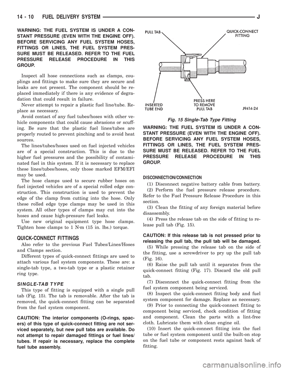
This type of fitting is equipped with a single pull
tab (Fig. 15). The tab is removable. After the tab is
removed, the quick-connect fitting can be separated
from the fuel system component.
CAUTION: The interior components (O-rings, spac-
ers) of this type of quick-connect fitting are not ser-
viced separately, but new pull tabs are available. Do
not attempt to repair damaged fittings or fuel lines/
tubes. If repair is necessary, replace the complete
fuel tube assembly.WARNING: THE FUEL SYSTEM IS UNDER A CON-
STANT PRESSURE (EVEN WITH THE ENGINE OFF).
BEFORE SERVICING ANY FUEL SYSTEM HOSES,
FITTINGS OR LINES, THE FUEL SYSTEM PRES-
SURE MUST BE RELEASED. REFER TO THE FUEL
PRESSURE RELEASE PROCEDURE IN THIS
GROUP.
DISCONNECTION/CONNECTION
(1) Disconnect negative battery cable from battery.
(2) Perform the fuel pressure release procedure.
Refer to the Fuel Pressure Release Procedure in this
section.
(3) Clean the fitting of any foreign material before
disassembly.
(4) Press the release tab on the side of fitting to re-
lease pull tab (Fig. 15).
CAUTION: If this release tab is not pressed prior to
releasing the pull tab, the pull tab will be damaged.
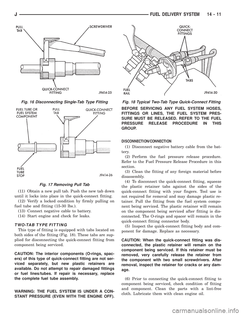
(5) While pressing the release tab on the side of
the fitting, use a screwdriver to pry up the pull tab
(Fig. 16).
(6) Raise the pull tab until it separates from the
quick-connect fitting (Fig. 17). Discard the old pull
tab.
(7) Disconnect the quick-connect fitting from the
fuel system component being serviced.
(8) Inspect the quick-connect fitting body and fuel
system component for damage. Replace as necessary.
(9) Prior to connecting the quick-connect fitting to
component being serviced, check condition of fitting
and component. Clean the parts with a lint-free
cloth. Lubricate them with clean engine oil.
(10) Insert the quick-connect fitting into the fuel
tube or fuel system component until the built-on stop
on the fuel tube or component rests against back of
fitting.
Fig. 15 Single-Tab Type Fitting
14 - 10 FUEL DELIVERY SYSTEMJ
Page 1413 of 2158
(11) Obtain a new pull tab. Push the new tab down
until it locks into place in the quick-connect fitting.
(12) Verify a locked condition by firmly pulling on
fuel tube and fitting (15-30 lbs.).
(13) Connect negative cable to battery.
(14) Start engine and check for leaks.
TWO-TAB TYPE FITTING
This type of fitting is equipped with tabs located on
both sides of the fitting (Fig. 18). These tabs are sup-
plied for disconnecting the quick-connect fitting from
component being serviced.
CAUTION: The interior components (O-rings, spac-
ers) of this type of quick-connect fitting are not ser-
viced separately, but new plastic retainers are
available. Do not attempt to repair damaged fittings
or fuel lines/tubes. If repair is necessary, replace
the complete fuel tube assembly.
WARNING: THE FUEL SYSTEM IS UNDER A CON-
STANT PRESSURE (EVEN WITH THE ENGINE OFF).BEFORE SERVICING ANY FUEL SYSTEM HOSES,
FITTINGS OR LINES, THE FUEL SYSTEM PRES-
SURE MUST BE RELEASED. REFER TO THE FUEL
PRESSURE RELEASE PROCEDURE IN THIS
GROUP.
DISCONNECTION/CONNECTION
(1) Disconnect negative battery cable from the bat-
tery.
(2) Perform the fuel pressure release procedure.
Refer to the Fuel Pressure Release Procedure in this
section.
(3) Clean the fitting of any foreign material before
disassembly.
(4) To disconnect the quick-connect fitting, squeeze
the plastic retainer tabs against the sides of the
quick-connect fitting with your fingers. Tool use is
not required for removal and may damage plastic re-
tainer. Pull the fitting from the fuel system compo-
nent being serviced. The plastic retainer will remain
on the component being serviced after fitting is dis-
connected. The O-rings and spacer will remain in the
quick-connect fitting connector body.
(5) Inspect the quick-connect fitting body and com-
ponent for damage. Replace as necessary.
CAUTION: When the quick-connect fitting was dis-
connected, the plastic retainer will remain on the
component being serviced. If this retainer must be
removed, very carefully release the retainer from
the component with two small screwdrivers. After
removal, inspect the retainer for cracks or any dam-
age.
(6) Prior to connecting the quick-connect fitting to
component being serviced, check condition of fitting
and component. Clean the parts with a lint-free
cloth. Lubricate them with clean engine oil.
Fig. 16 Disconnecting Single-Tab Type Fitting
Fig. 17 Removing Pull Tab
Fig. 18 Typical Two-Tab Type Quick-Connect Fitting
JFUEL DELIVERY SYSTEM 14 - 11
Page 1414 of 2158
(7) Insert the quick-connect fitting to the compo-
nent being serviced and into the plastic retainer.
When a connection is made, a click will be heard.
(8) Verify a locked condition by firmly pulling on
fuel tube and fitting (15-30 lbs.).
(9) Connect negative cable to battery.
(10) Start engine and check for leaks.
PLASTIC RETAINER RING TYPE FITTING
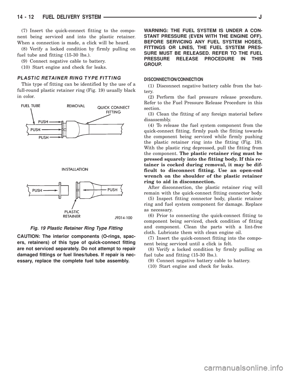
This type of fitting can be identified by the use of a
full-round plastic retainer ring (Fig. 19) usually black
in color.
CAUTION: The interior components (O-rings, spac-
ers, retainers) of this type of quick-connect fitting
are not serviced separately. Do not attempt to repair
damaged fittings or fuel lines/tubes. If repair is nec-
essary, replace the complete fuel tube assembly.WARNING: THE FUEL SYSTEM IS UNDER A CON-
STANT PRESSURE (EVEN WITH THE ENGINE OFF).
BEFORE SERVICING ANY FUEL SYSTEM HOSES,
FITTINGS OR LINES, THE FUEL SYSTEM PRES-
SURE MUST BE RELEASED. REFER TO THE FUEL
PRESSURE RELEASE PROCEDURE IN THIS
GROUP.
DISCONNECTION/CONNECTION
(1) Disconnect negative battery cable from the bat-
tery.
(2) Perform the fuel pressure release procedure.
Refer to the Fuel Pressure Release Procedure in this
section.
(3) Clean the fitting of any foreign material before
disassembly.
(4) To release the fuel system component from the
quick-connect fitting, firmly push the fitting towards
the component being serviced while firmly pushing
the plastic retainer ring into the fitting (Fig. 19).
With the plastic ring depressed, pull the fitting from
the component.The plastic retainer ring must be
pressed squarely into the fitting body. If this re-
tainer is cocked during removal, it may be dif-
ficult to disconnect fitting. Use an open-end
wrench on the shoulder of the plastic retainer
ring to aid in disconnection.
After disconnection, the plastic retainer ring will
remain with the quick-connect fitting connector body.
(5) Inspect fitting connector body, plastic retainer
ring and fuel system component for damage. Replace
as necessary.
(6) Prior to connecting the quick-connect fitting to
component being serviced, check condition of fitting
and component. Clean the parts with a lint-free
cloth. Lubricate them with clean engine oil.
(7) Insert the quick-connect fitting into the compo-
nent being serviced until a click is felt.
(8) Verify a locked condition by firmly pulling on
fuel tube and fitting (15-30 lbs.).
(9) Connect negative battery cable to battery.
(10) Start engine and check for leaks.
Fig. 19 Plastic Retainer Ring Type Fitting
14 - 12 FUEL DELIVERY SYSTEMJ
Page 1434 of 2158
²The PCM adjusts ignition timing by increasing
and decreasing spark advance.
²The PCM operates the A/C compressor clutch
through the clutch relay. This happens if A/C has
been selected by the vehicle operator and requested
by the A/C thermostat.
The optional Extended Idle Switch is used to raise
the engine idle speed to approximately 1000 rpm.
This is when the shifter is in either the Park or Neu-
tral position. A rocker-type 2-wire switch (extended
idle switch) is mounted to the instrument panel. This
switch will supply a ground circuit to the powertrain
control module (PCM).The switch is available
only with 4.0L engine when supplied with the
optional police package.
CRUISE MODE
When the engine is at operating temperature, this
is a Closed Loop mode. At cruising speed, the power-
train control module (PCM) receives inputs from:
²Air conditioning select signal (if equipped)
²Air conditioning request signal (if equipped)
²Battery voltage
²Engine coolant temperature sensor
²Crankshaft position sensor
²Intake manifold air temperature sensor
²Manifold absolute pressure (MAP) sensor
²Throttle position sensor (TPS)
²Camshaft position sensor signal (in the distribu-
tor)
²Park/neutral switch (gear indicator signalÐauto.
trans. only)
²Oxygen (O2S) sensor
Based on these inputs, the following occurs:
²Voltage is applied to the fuel injectors with the
PCM. The PCM will then adjust the injector pulse
width by turning the ground circuit to each individ-
ual injector on and off.
²The PCM monitors the O2S sensor input and ad-
justs air-fuel ratio. It also adjusts engine idle speed
through the idle air control (IAC) motor.
²The PCM adjusts ignition timing by turning the
ground path to the coil on and off.
²The PCM operates the A/C compressor clutch
through the clutch relay. This happens if A/C has
been selected by the vehicle operator and requested
by the A/C thermostat.
ACCELERATION MODE
This is an Open Loop mode. The powertrain control
module (PCM) recognizes an abrupt increase in
throttle position or MAP pressure as a demand for
increased engine output and vehicle acceleration. The
PCM increases injector pulse width in response to in-
creased throttle opening.
DECELERATION MODE
When the engine is at operating temperature, this
is an Open Loop mode. During hard deceleration, the
powertrain control module (PCM) receives the follow-
ing inputs.
²Air conditioning select signal (if equipped)
²Air conditioning request signal (if equipped)
²Battery voltage
²Engine coolant temperature sensor
²Crankshaft position sensor
²Intake manifold air temperature sensor
²Manifold absolute pressure (MAP) sensor
²Throttle position sensor (TPS)
²Camshaft position sensor signal (in the distribu-
tor)
²Park/neutral switch (gear indicator signalÐauto.
trans. only)
If the vehicle is under hard deceleration with the
proper rpm and closed throttle conditions, the PCM
will ignore the oxygen sensor input signal. The PCM
will enter a fuel cut-off strategy in which it will not
supply battery voltage to the injectors. If a hard de-
celeration does not exist, the PCM will determine the
proper injector pulse width and continue injection.
Based on the above inputs, the PCM will adjust en-
gine idle speed through the idle air control (IAC) mo-
tor.
The PCM adjusts ignition timing by turning the
ground path to the coil on and off.
The PCM opens the ground circuit to the A/C
clutch relay to disengage the A/C compressor clutch.
This is done until the vehicle is no longer under de-
celeration (if the A/C system is operating).
WIDE OPEN THROTTLE MODE
This is an Open Loop mode. During wide open
throttle operation, the powertrain control module
(PCM) receives the following inputs.
²Battery voltage
²Crankshaft position sensor
²Engine coolant temperature sensor
²Intake manifold air temperature sensor
²Manifold absolute pressure (MAP) sensor
²Throttle position sensor (TPS)
²Camshaft position sensor signal (in the distribu-
tor)
During wide open throttle conditions, the following
occurs:
²Voltage is applied to the fuel injectors with the
powertrain control module (PCM). The PCM will
then control the injection sequence and injector pulse
width by turning the ground circuit to each individ-
ual injector on and off. The PCM ignores the oxygen
sensor input signal and provides a predetermined
amount of additional fuel. This is done by adjusting
injector pulse width.
²The PCM adjusts ignition timing by turning the
ground path to the coil on and off.
14 - 32 FUEL SYSTEM COMPONENT DESCRIPTION/SYSTEM OPERATIONJ
Page 1460 of 2158
MULTI-PORT FUEL INJECTION (MFI)ÐCOMPONENT REMOVAL/INSTALLATION
INDEX
page page
Accelerator Pedal and Throttle Cable........... 58
Air Cleaner Element....................... 59
Air Cleaner Housing....................... 58
Air Conditioning (A/C) Clutch Relay............ 58
Automatic Shutdown (ASD) Relay............. 59
Brake Switch............................ 59
Camshaft Position Sensor................... 60
Crankshaft Position Sensor.................. 60
Engine Coolant Temperature Sensor........... 60
Fuel Filter............................... 60
Fuel Injector............................. 60
Fuel Pressure Regulator.................... 61
Fuel Pump Module........................ 61
Fuel Pump Relay......................... 61
Fuel Rail Assembly........................ 62
Fuel System Pressure Release Procedure....... 62
Fuel Tank Pressure Relief/Rollover Valve........ 62Fuel Tanks.............................. 62
Fuel Tubes/Lines/Hoses and Clamps........... 62
Idle Air Control (IAC) Motor.................. 62
Ignition Coil............................. 62
Intake Manifold........................... 63
Intake Manifold Air Temperature Sensor......... 60
Manifold Absolute Pressure (Map) Sensor....... 63
Oxygen (O2S) Sensor...................... 63
Park Neutral Switch....................... 63
Power Steering Pressure SwitchÐ2.5L
Engine Only............................ 63
Powertrain Control Module (PCM)............. 64
Quick-Connect Fittings..................... 64
Throttle Body............................ 64
Throttle Position Sensor (TPS)............... 65
Torque Converter Clutch Relay............... 65
Vehicle Speed Sensor...................... 66
ACCELERATOR PEDAL AND THROTTLE CABLE
Refer to the Accelerator Pedal and Throttle Cable
section of this group for removal/installation proce-
dures.
AIR CONDITIONING (A/C) CLUTCH RELAY
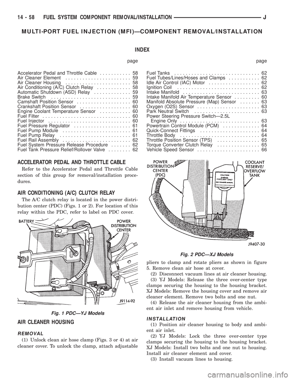
The A/C clutch relay is located in the power distri-
bution center (PDC) (Figs. 1 or 2). For location of this
relay within the PDC, refer to label on PDC cover.
AIR CLEANER HOUSING
REMOVAL
(1) Unlock clean air hose clamp (Figs. 3 or 4) at air
cleaner cover. To unlock the clamp, attach adjustablepliers to clamp and rotate pliers as shown in figure
5. Remove clean air hose at cover.
(2) Disconnect vacuum lines at air cleaner housing.
(3) YJ Models: Release the three over-center type
clamps securing the housing to the housing bracket.
XJ Models: Remove the housing cover and remove air
cleaner element. Remove two bolts and one nut.
(4) Release the air cleaner housing from the ambi-
ent air inlet and remove housing from vehicle.
INSTALLATION
(1) Position air cleaner housing to body and ambi-
ent air inlet.
(2) YJ Models: Lock the three over-center type
clamps securing the housing to the housing bracket.
XJ Models: Install two bolts and one nut to housing.
Install air cleaner element and cover.
(3) Install vacuum lines to housing.
Fig. 1 PDCÐYJ Models
Fig. 2 PDCÐXJ Models
14 - 58 FUEL SYSTEM COMPONENT REMOVAL/INSTALLATIONJ
Page 1485 of 2158
STEERING
CONTENTS
page page
GENERAL INFORMATION.................. 1
GENERAL INFORMATION................. 48
MANUAL STEERING GEAR................ 37
POWER STEERING PUMP................. 11
POWER STEERING SYSTEM DIAGNOSIS...... 3
RECIRCULATING BALL POWER STEERING
GEAR............................... 21STEERING COLUMN GENERAL SERVICEÐXJ . 47
STEERING COLUMNÐYJ................. 58
STEERING LINKAGEÐXJ................. 16
STEERING LINKAGEÐYJ................. 19
STEERING RHD......................... 74
TORQUE SPECIFICATIONS................ 78
GENERAL INFORMATION
STEERING SYSTEM COMPONENTS
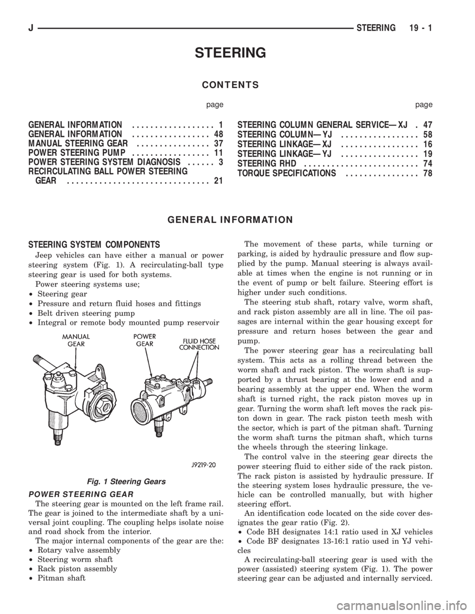
Jeep vehicles can have either a manual or power
steering system (Fig. 1). A recirculating-ball type
steering gear is used for both systems.
Power steering systems use;
²Steering gear
²Pressure and return fluid hoses and fittings
²Belt driven steering pump
²Integral or remote body mounted pump reservoir
POWER STEERING GEAR
The steering gear is mounted on the left frame rail.
The gear is joined to the intermediate shaft by a uni-
versal joint coupling. The coupling helps isolate noise
and road shock from the interior.
The major internal components of the gear are the:
²Rotary valve assembly
²Steering worm shaft
²Rack piston assembly
²Pitman shaftThe movement of these parts, while turning or
parking, is aided by hydraulic pressure and flow sup-
plied by the pump. Manual steering is always avail-
able at times when the engine is not running or in
the event of pump or belt failure. Steering effort is
higher under such conditions.
The steering stub shaft, rotary valve, worm shaft,
and rack piston assembly are all in line. The oil pas-
sages are internal within the gear housing except for
pressure and return hoses between the gear and
pump.
The power steering gear has a recirculating ball
system. This acts as a rolling thread between the
worm shaft and rack piston. The worm shaft is sup-
ported by a thrust bearing at the lower end and a
bearing assembly at the upper end. When the worm
shaft is turned right, the rack piston moves up in
gear. Turning the worm shaft left moves the rack pis-
ton down in gear. The rack piston teeth mesh with
the sector, which is part of the pitman shaft. Turning
the worm shaft turns the pitman shaft, which turns
the wheels through the steering linkage.
The control valve in the steering gear directs the
power steering fluid to either side of the rack piston.
The rack piston is assisted by hydraulic pressure. If
the steering system loses hydraulic pressure, the ve-
hicle can be controlled manually, but with higher
steering effort.
An identification code located on the side cover des-
ignates the gear ratio (Fig. 2).
²Code BH designates 14:1 ratio used in XJ vehicles
²Code BF designates 13-16:1 ratio used in YJ vehi-
cles
A recirculating-ball steering gear is used with the
power (assisted) steering system (Fig. 1). The power
steering gear can be adjusted and internally serviced.
Fig. 1 Steering Gears
JSTEERING 19 - 1
Page 1629 of 2158
30RH/32RH AUTOMATIC TRANSMISSION
GENERAL INFORMATION
INDEX
page page
Recommended Fluid....................... 67
Torque Converter......................... 67
Transmission Application.................... 67
Transmission Changes and Parts Interchangeability.. 67
Transmission Controls and Components........ 67
Transmission Identification.................. 67
TRANSMISSION APPLICATION
Chrysler 30RH and 32RH automatic transmissions
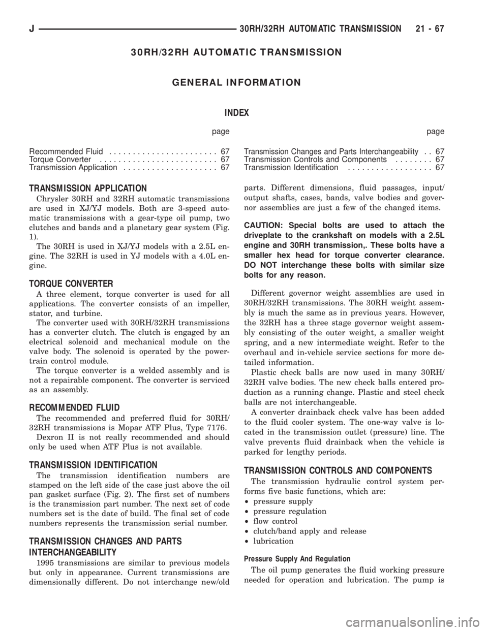
are used in XJ/YJ models. Both are 3-speed auto-
matic transmissions with a gear-type oil pump, two
clutches and bands and a planetary gear system (Fig.
1).
The 30RH is used in XJ/YJ models with a 2.5L en-
gine. The 32RH is used in YJ models with a 4.0L en-
gine.
TORQUE CONVERTER
A three element, torque converter is used for all
applications. The converter consists of an impeller,
stator, and turbine.
The converter used with 30RH/32RH transmissions
has a converter clutch. The clutch is engaged by an
electrical solenoid and mechanical module on the
valve body. The solenoid is operated by the power-
train control module.
The torque converter is a welded assembly and is
not a repairable component. The converter is serviced
as an assembly.
RECOMMENDED FLUID
The recommended and preferred fluid for 30RH/
32RH transmissions is Mopar ATF Plus, Type 7176.
Dexron II is not really recommended and should
only be used when ATF Plus is not available.
TRANSMISSION IDENTIFICATION
The transmission identification numbers are
stamped on the left side of the case just above the oil
pan gasket surface (Fig. 2). The first set of numbers
is the transmission part number. The next set of code
numbers set is the date of build. The final set of code
numbers represents the transmission serial number.
TRANSMISSION CHANGES AND PARTS
INTERCHANGEABILITY
1995 transmissions are similar to previous models
but only in appearance. Current transmissions are
dimensionally different. Do not interchange new/oldparts. Different dimensions, fluid passages, input/
output shafts, cases, bands, valve bodies and gover-
nor assemblies are just a few of the changed items.
CAUTION: Special bolts are used to attach the
driveplate to the crankshaft on models with a 2.5L
engine and 30RH transmission,. These bolts have a
smaller hex head for torque converter clearance.
DO NOT interchange these bolts with similar size
bolts for any reason.
Different governor weight assemblies are used in
30RH/32RH transmissions. The 30RH weight assem-
bly is much the same as in previous years. However,
the 32RH has a three stage governor weight assem-
bly consisting of the outer weight, a smaller weight
spring, and a new intermediate weight. Refer to the
overhaul and in-vehicle service sections for more de-
tailed information.
Plastic check balls are now used in many 30RH/
32RH valve bodies. The new check balls entered pro-
duction as a running change. Plastic and steel check
balls are not interchangeable.
A converter drainback check valve has been added
to the fluid cooler system. The one-way valve is lo-
cated in the transmission outlet (pressure) line. The
valve prevents fluid drainback when the vehicle is
parked for lengthy periods.
TRANSMISSION CONTROLS AND COMPONENTS
The transmission hydraulic control system per-
forms five basic functions, which are:
²pressure supply
²pressure regulation
²flow control
²clutch/band apply and release
²lubrication
Pressure Supply And Regulation
The oil pump generates the fluid working pressure
needed for operation and lubrication. The pump is
J30RH/32RH AUTOMATIC TRANSMISSION 21 - 67
Page 1661 of 2158
30RH/32RH IN-VEHICLE SERVICE
INDEX
page page
Converter Drainback Check Valve Service...... 113
Fluid and Filter Replacement................. 99
Fluid Level Check......................... 99
Front Band Adjustment.................... 102
Governor and Park Gear Service............. 105
Oil Filter Replacement..................... 103
Park Interlock Cable Adjustment (XJ).......... 101
Park Lock Component Replacement.......... 108
Park/Neutral Position Switch Service.......... 109
Rear Band Adjustment.................... 103
Recommended Fluid....................... 99Refilling After Overhaul or Fluid/Filter Change . . . 100
Shift Cable Adjustment (XJ)................. 100
Shift Linkage Adjustment (YJ)............... 100
Speedometer Service..................... 109
Throttle Valve Cable Adjustment (XJ/YJ)....... 101
Transmission Cooler Flow Testing............ 113
Transmission Cooler Line and Fitting Service.... 111
Transmission Cooler Reverse Flushing......... 114
Valve Body Installation.................... 104
Valve Body Removal...................... 104
Valve Body Service....................... 104
RECOMMENDED FLUID
Recommended (and preferred) fluid for 30RH/32RH
transmissions is Mopar ATF Plus, type 7176.
Dexron II is not really recommended and should
only be used when ATF Plus is not available.
FLUID LEVEL CHECK
Transmission fluid level should be checked monthly
under normal operation. If the vehicle is used for
trailer towing or similar heavy load hauling, check
fluid level and condition weekly.
Fluid level is checked with the engine running at
curb idle speed, the transmission in Neutral and the
transmission fluid at normal operating temperature.
FLUID LEVEL CHECK PROCEDURE
(1) Transmission fluid must be at normal operating
temperature for accurate fluid level check. Drive ve-
hicle if necessary to bring fluid temperature up to
normal hot operating temperature of 82ÉC (180ÉF).
(2) Position vehicle on level surface. This is ex-
tremely important for accurate fluid level check.
(3) Start and run engine at curb idle speed.
(4) Apply parking brakes.
(5) Shift transmission momentarily into all gear
ranges. Then shift transmission back to Neutral.
(6) Clean top of filler tube and dipstick to keep dirt
from entering tube.
(7) Remove dipstick and check fluid level as fol-
lows:
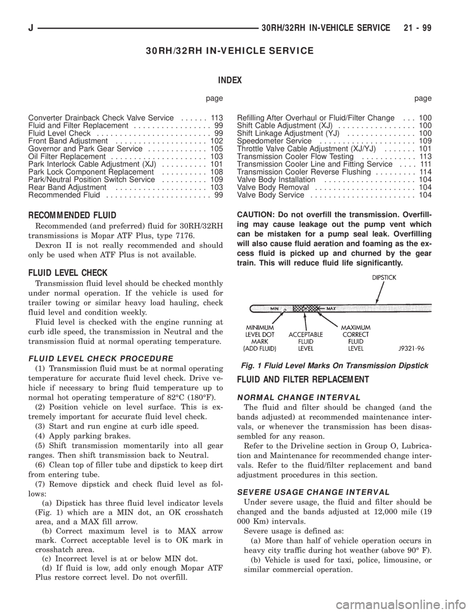
(a) Dipstick has three fluid level indicator levels
(Fig. 1) which are a MIN dot, an OK crosshatch
area, and a MAX fill arrow.
(b) Correct maximum level is to MAX arrow
mark. Correct acceptable level is to OK mark in
crosshatch area.
(c) Incorrect level is at or below MIN dot.
(d) If fluid is low, add only enough Mopar ATF
Plus restore correct level. Do not overfill.CAUTION: Do not overfill the transmission. Overfill-
ing may cause leakage out the pump vent which
can be mistaken for a pump seal leak. Overfilling
will also cause fluid aeration and foaming as the ex-
cess fluid is picked up and churned by the gear
train. This will reduce fluid life significantly.
FLUID AND FILTER REPLACEMENT
NORMAL CHANGE INTERVAL
The fluid and filter should be changed (and the
bands adjusted) at recommended maintenance inter-
vals, or whenever the transmission has been disas-
sembled for any reason.
Refer to the Driveline section in Group O, Lubrica-
tion and Maintenance for recommended change inter-
vals. Refer to the fluid/filter replacement and band
adjustment procedures in this section.
SEVERE USAGE CHANGE INTERVAL
Under severe usage, the fluid and filter should be
changed and the bands adjusted at 12,000 mile (19
000 Km) intervals.
Severe usage is defined as:
(a) More than half of vehicle operation occurs in
heavy city traffic during hot weather (above 90É F).
(b) Vehicle is used for taxi, police, limousine, or
similar commercial operation.
Fig. 1 Fluid Level Marks On Transmission Dipstick
J30RH/32RH IN-VEHICLE SERVICE 21 - 99